EMKO EZM-7750 User manual

___________________________________________________________________________________________________
_________________________________________________________________________________________
Page 1/ 30 EZM7750_ENG_VER11
Instruction Manual
EZM-7750 72X72DIN 1/8
Multi-Functional Timer & Counter
•6 digit actual, 6 digit set display
•Operating with 2 sets
•
Reset, pause and ChA-ChB counter inputs
•Selectable NPN/PNP input types
•Programmable Counter/Totalizer Counter,
Batch Counter, Timer, Chronometer,
Frequencymeter and Tachometer
functions
•Programmable time scale (Second,
Minute, Hour) for Timer and Chronometer
•Operating with Automatic and Manual
Reset
•For counting function, selectable INC,
DEC, INC/INC, INC/DEC, UP/DOWN,
•
x1 / x2 / x4 (with encoder) type of counting
•Coefficient and decimal point position
•Programmable alarm functions in
Frequencymeter and Tachometer modes.
•Operating by absolute or offset in Counter
mode.
•Optional serial communication with
MODBUS via RS-232 or RS-485

___________________________________________________________________________________________________
_________________________________________________________________________________________
Page 2/ 30 EZM7750_ENG_VER11
INSTRUCTION MANUAL..............................................................................................................1
EU DECLARATION OF CONFORMITY.............................................................................................3
1 INTRODUCTION:...............................................................................................................................5
1.1 MODEL CODE:............................................................................................................................6
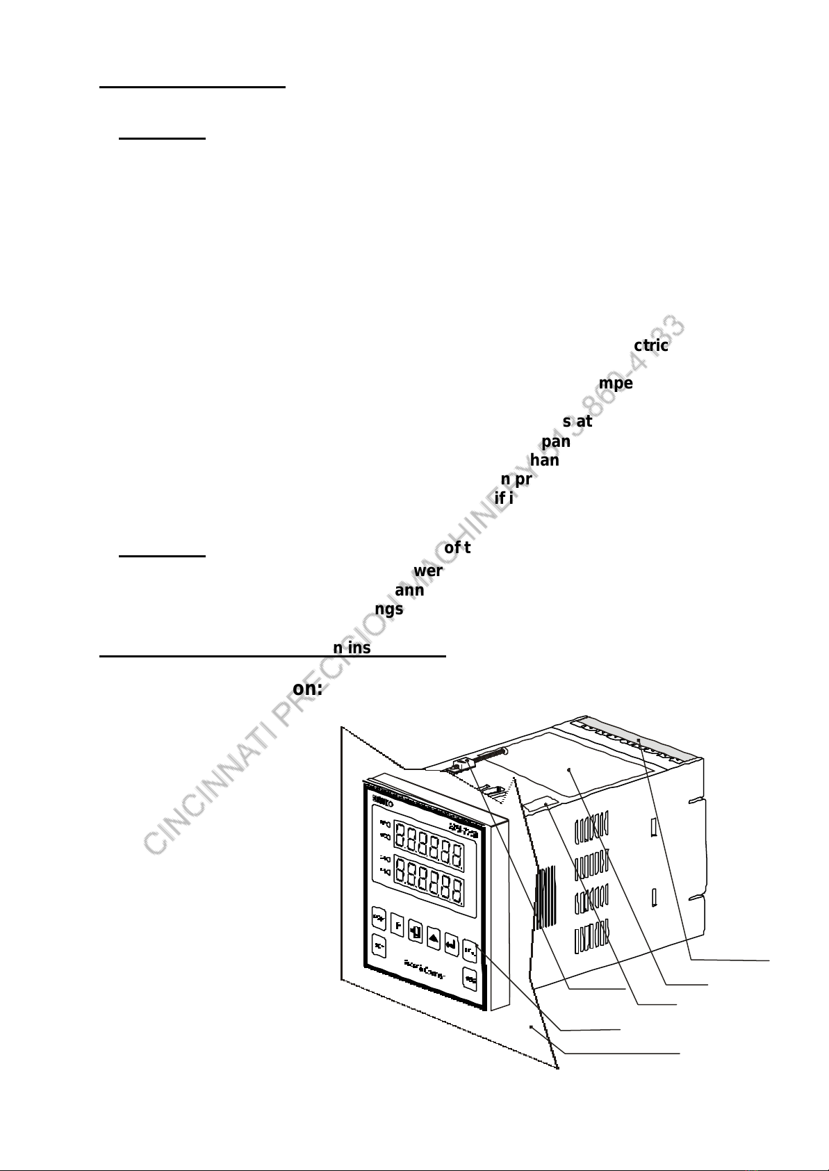
2 INSTALLATION:.................................................................................................................................7
2.1 GENERAL DESCRIPTION:........................................................................................................7
2.2 DIMENSIONS:..............................................................................................................................8
2.3 PANEL CUT-OUT:.......................................................................................................................8
2.4 ENVIRONMENTAL RATINGS:..................................................................................................8
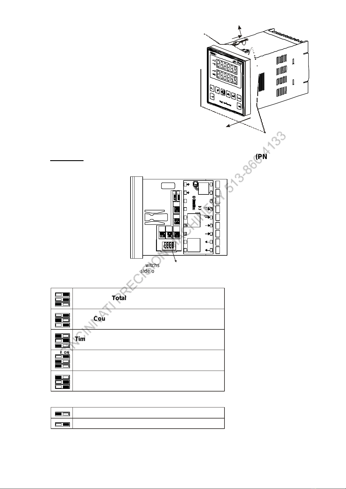
2.5 PANEL MOUNTING:...................................................................................................................9
2.6 OPERATING FUNCTION SELECTION BY DIP SWITCHES:...........................................10
3 ELECTRICAL CONNECTIONS:....................................................................................................11
3.1 TERMINAL LAYOUT AND CONNECTION INSTRUCTION:..............................................12
3.2 POWER SUPPLY:.....................................................................................................................12
3.3 INPUTS:......................................................................................................................................13
3.4 I/O MODULES INSTALLATION:.............................................................................................14
OPERATING MANUAL.......................................................................................................................17
4 FRONT PANEL DESCRIPTION:...................................................................................................17
4.1 SET-1 & SET-2 ADJUSTMENTS:...........................................................................................18
4.2 OBSERVING AND CHANGING PARAMETER VALUES:..................................................18
4.3 PARAMETERS LIST:................................................................................................................19
4.4 OUTPUT FUNCTIONS:............................................................................................................24
TECHNICAL SPECIFICATIONS:......................................................................................................30

___________________________________________________________________________________________________
_________________________________________________________________________________________
Page 3/ 30 EZM7750_ENG_VER11
EU DECLARATION OF CONFORMITY
Manufacturer's Name :EMKO ELEKTRONIK A.S.
Manufacturer's Address :DOSAB, Karanfil Sk., No 6,
16369 Bursa, TURKEY
The manufacturer hereby declares that the product:
Product Name :Programmable Timer & Counter Unit
Model Number :EZM-7750
Type Number :EZM-7750
Product Category :Electrical equipment for measurement,
control and laboratory use
Conforms to the following directives:
73 / 23 / EEC The Low Voltage Directive as amended by 93 / 68 / EEC
89 / 336 / EEC The Electromagnetic Compatibility Directive
has been designed and manufactured to the following specifications:
EN 50081-2 EMC Generic Emission Standard for the Industrial Environment
EN 50082-2 EMC Generic Immunity Standard for the Industrial Environment
EN 61010-1 Safety Requirements for electrical equipment for measurement, control and
laboratory use

___________________________________________________________________________________________________
_________________________________________________________________________________________
Page 4/ 30 EZM7750_ENG_VER11
Please read the following information before using and thank you very
much for buying Emko’ s product.
The safety requirements are classified as either “warning“ and “caution” according to
the following explanations:
χχ WARNING: Suggest that the user’ s mishandling can results in personal death or
serious injury.
χχ CAUTION: Suggest that the user’ s mishandling can results in personal injury or
damage to the property.
Pack List:
1- One piece unit.
2- Two pieces fixing clamps.
3- One piece “user manual”.

___________________________________________________________________________________________________
_________________________________________________________________________________________
Page 5/ 30 EZM7750_ENG_VER11
1 INTRODUCTION:
EZM series multifunctional counters can be used beside packing machines, production and
quality control rollers, in cutting and processing machine of glass, plastic, marble, sheet iron,
fabric all measuring and controlling of dimension, count, total count, speed, tachometer,
productivity, time and can be adapted easily to all mechanical construction and automation
systems.

___________________________________________________________________________________________________
_________________________________________________________________________________________
Page 6/ 30 EZM7750_ENG_VER11
1.1 MODEL CODE:
EZM-7750
(72x72 DIN 1/8)
Supply Voltage
85-264VAC 50/60Hz
15 to 30VAC 50/60 Hz, 18 to 36VDC
Customer
A
A
1
0
00
00
0
0
01
01
1
1
02
02
2
3
4
0
1
2
Non
Non
Non
Counter and Totalizer Counter
NPN
Relay Output Module
Relay Output Module
Batch Counter
PNP
SSR Drive Output Module
Timer
Frequencymeter and Tachometer
Chronometer
Non
RS-232
RS-485 (MODBUS)
2
9
BC DEFG HI /
/
UVWZ/
/000 0 0
Output-1
Module-1
Module-2
Function of Device
Input Type
Serial Interface
E
FG
HI
U
V
D
03 Transistor Output Module

___________________________________________________________________________________________________
_________________________________________________________________________________________
Page 7/ 30 EZM7750_ENG_VER11
2 INSTALLATION:
χχWARNING:
1- A visual inspection of this product for possible damage occurred during shipment
is recommended before installation. It is your responsibility to ensure that qualified
mechanical and electrical technicians install this product.
2- If there is danger of serious accident resulting from a failure or defect in this unit,
provide the unit with an appropriate external protective circuit to prevent an
accident.
3- The unit is normally supplied without a power switch or a fuse. Use power switch
and fuse as required (fuse rating is1A@250VAC)
4- Be sure to use the rated power supply voltage to protect the unit against damage
and to prevent failure.
5- Keep the power off until all of the wiring is completed so that electric shock and
trouble with the unit can be prevented.
6- Never attempt to disassemble, modify, or repair this unit. Tampering with the unit
may results in malfunction, electric shock, or fire.
7- Do not use the unit in combustible or explosive gaseous atmospheres.
8- During the equipment is putted in hole on the metal panel while mechanical
installation some metal burrs can cause injury on hands, you should be careful.
Installation parts of equipment should be tighten properly. The equipment can be
drop from mounting place reason of vibration if installation parts leave soft.
χχWARNING: Before beginning installation of this product:
-Disconnect all electrical power to the machine.
-Make sure the machine cannot operate during installation.
-Follow all safety warnings of the machine manufacturer.
Read and follow all installation instructions.
2.1 General Description:
Panel Surface (max thickness 15mm)
Front Panel
IP65 protection
NEMA4X
Mounting clamps
Productlabel
Terminal protection cover
DIP Switch cover

___________________________________________________________________________________________________
_________________________________________________________________________________________
Page 8/ 30 EZM7750_ENG_VER11
2.2 Dimensions:
2.3 Panel Cut-Out:
2.4 Environmental Ratings:
Operating Conditions:
Operating temperature : -5 ... +55°C
Maximum operating humidity : 90% Rh (non-condensing)
Altitude : Up to 2000 m.
χχCAUTION:
Forbidden Conditions:
Corrosive atmosphere
Explosive atmosphere
Home application (The unit is only for industrial applications)
72mm/2,83”
72mm / 2,83” 76mm/2,99”11.5/0.45"
97 mm/3,81in (min)
72 mm/2,83in(min)
72 mm/2,83in (min)
97 mm/3,81in(min)

___________________________________________________________________________________________________
_________________________________________________________________________________________
Page 9/ 30 EZM7750_ENG_VER11
2.5 Panel Mounting:
Insert To Panel:
χχWARNING: During the equipment is putted in hole on the metal panel while
mechanical installation some metal burrs can cause injury on hands, you should be
careful. Installation parts of equipment should be tighten properly. The equipment can
be drop from mounting place reason of vibration if installation parts leave soft.
1- Prepare panel cut-out.
2- Check front panel gasket position.
3- Insert the device trough the cut-out.
Installation Fixing Clamp:
The unit is designed for panel mounting.
Fixing is by mounting clamp.
1. Insert the unit in the panel
cut-out from the front.
2. Insert the mounting clamp
from the rear side of the device
and tighten the fixing screws
to secure the unit against the panel.
1
2
3
1
2

___________________________________________________________________________________________________
_________________________________________________________________________________________
Page 10 / 30 EZM7750_ENG_VER11
Pulling Fixing Clamp:
1- You can unscrew to screws.
2- Pull the mounting clamp by screw driver
from the front side of the device.
3- Pull the unit in the panel
cut-out.
2.6 Operating Function Selection by DIP Switches:
χχCAUTION:You can select to operating function and input type (PNP or NPN) by DIP
Switch on the device.
4
4
Counter and Totalizer Counter
Choosing to Function
Input Type Selection
Batch Counter
Timer
Chronometer
NPN
PNP
Frequencymeter and Tachometer
ON
ON
1
2
3
ONOFF
1
2
3
ONOFF
1
2
3
ONOFF
1
2
3
ONOFF
1
2
3
ONOFF
OFF
OFF
1
2
3
1
1
1
1 1 1 4
4
ON
ON
ON
ONONONON
ON
OFF
OFF Counter
&
Totalizer
Batch
Counter
TimerTacho Chrono PNP
NPN
OFF
OFF OFF OFF OFF
OFF
2
2
2
2 2 2
3
3
3
3 3 3
4
10
12Vdc
Max.50mA
0Vdc
ChA
ChB
PAUSE
RESET
8 5 to2 64 Va c
MODULE-1
MODULE-2
1
11
2
12
P/N:EZM-7750
3
13
4
14
5
15
6
16
7
17
8
18
9
NL
DIP Switchs are under the cover and cover is on
top side of the device.

___________________________________________________________________________________________________
_________________________________________________________________________________________
Page 11 / 30 EZM7750_ENG_VER11
3 ELECTRICAL CONNECTIONS:
χχWARNING:
You must ensure that the controller is correctly configured for your application.
Incorrect configuration could result in damage to the process being controlled, and/or
personal injury. It is your responsibility, as the installer, to ensure that the
configuration is correct. The controller may either have been configured when
ordered, or may need configuring now.
χχWARNING:
This equipment does not contain any parts and material related to users. Only
qualified personnel and technician trained specially should work on this equipment.
This equipment contains dangerous voltage inner circuits for human life. There is
severe dangerous for human life on the case of unauthorised intervene.
χχWARNING:
Before the connecting of module terminals, you must ensure that correct I/O modules
installed in the device.
χχWARNING:
Be sure to use the rated power supply voltage to protect the unit against damage and
to prevent failure.
χχWARNING:
Keep the power off until all of the wiring is completed so that electric shock and
trouble with the unit can be prevented.
12Vdc
Ma x.5 0mA
0Vdc
ChA
ChB
PAUS E
RES ET
1
10
2
11
3
12
4
13
5
14
6
15
7
16
8
17
9
18
10
PowerSupply
ModuleOutputTerminal
1
11
2
12
MODULE-1
MODULE-2
3
13
4
14
5
15
6 8
16
7 9
17 18
! !
1
1
1
1 1 1 4
4
ON
ON
ON
ON ON ON ON
ON
OFF
OFF Counter
&
Totalizer
Batch
Counter
Timer Tacho Chrono PNP
NPN
OFF
OFF OFF OFF OFF
OFF
2
2
2
2 2 2
3
3
3
3 3 3
4
10
12 Vdc
Ma x.50 mA
0Vdc
ChA
ChB
PAUS E
RE SET
85 to 264 Vac
MODULE-1
MODULE-2
1
11
2
12
P/N : EZM-7750
3
13
4
14
5
15
6
16
7
17
8
18
9
NL

___________________________________________________________________________________________________
_________________________________________________________________________________________
Page 12 / 30 EZM7750_ENG_VER11
3.1 Terminal Layout and Connection Instruction:
3.2 Power Supply:
17 18
LN
Fuse (1 A)
Switching power supply with multiple isolation
Supply
Power Switch
High voltage version:
85 to 264 V~, frequency 50 / 60Hz.
Low voltage version:
15 to 30 V~, frequency 50 / 60Hz.
18 to 36 VZ
1
10
2
11
3
12
4
13
5
14
6
15
7
16
8
17
9
18
0,5Nm
6mm / 0,23in
Wire Size:
18AWG/1mm²
Solid/Stranded
12 screw terminal M3
Option terminals
Holding screw 0,5Nm
Screw driver 0,8x3mm
Empty terminals

___________________________________________________________________________________________________
_________________________________________________________________________________________
Page 13 / 30 EZM7750_ENG_VER11
3.3 Inputs:
11
1 1
1 1
44
4 4
4 4
22
2 2
2 2
55
5 5
5 5
33
3 3
3 3
66
6 6
6 6
12 Vdc
Max.50mA
12 Vdc
Max.50mA
12 Vdc
Max.50mA
12 Vdc
Max.50mA
12 Vdc
Max.50mA
12 Vdc
Max.50mA
0Vdc
0Vdc
0Vdc
0Vdc
0Vdc
0Vdc
ChA
ChA
ChA
ChA
ChA
ChA
ChB
ChB
ChB
ChB
ChB
ChB
PAUSE
PAUSEPAUSE
PAUSE
PAUSE
PAUSE SWITCH
SWITCHSWITCH
SWITCH
SWITCH
SWITCH
SWITCH
SWITCH
SWITCH
SWITCH
PROX.
PROX. PROX.
PROX.
INCREMENTAL ENCODER
10 to 30Vdc INCREMENTAL ENCODER
10 to 30Vdc
SWITCH
SWITCHSWITCH
SWITCH
SWITCH
SWITCH RESET
RESETRESET
RESET
RESET
RESET
NOTE 1
NOTE 1
NOTE 1 NOTE 1
NOTE 1 NOTE 1
NPNPNP
DIP SWITCH SETTING : NPN
Proximity & switch connection
DIP SWITCH SETTING : PNP
Proximity & switch connection
DIP SWITCH SETTING : PNP
Switch connection DIP SWITCH SETTING : NPN
Switch connection
DIP SWITCH SETTING : PNP
Incremental Encoder & switch connection DIP SWITCH SETTING : NPN
Incremental Encoder & switch connection
NPNPNP
NOTE 1:
Auxiliary power supply for external transmitter
12Vdc ±10% / 50mA max with short circuit protection

___________________________________________________________________________________________________
_________________________________________________________________________________________
Page 14 / 30 EZM7750_ENG_VER11
3.4 I/O Modules Installation:
First, detach all cable
connections from the device
and uninstall it from the panel
Suppress to the lock pins where
top and bottom of the device
Pull the cover case
by your hand
through rear side
Pull out the cover case
from the device
1
2
3
4
Slide input / output modules
in to cavity
5
Replace the cover case by
taking care of the terminal
numbers should be at right
orientation.
6

___________________________________________________________________________________________________
_________________________________________________________________________________________
Page 15 / 30 EZM7750_ENG_VER11
OUTPUT MODULES:
χχCAUTION:
Make sure the load does not exceed the rated capacity of the relay.
10
13
Module-1 / Module-2 Optional Output Modules
Module-1 Terminal
Module-2 Terminal
11
14
NOC
Relay Out. Module
EMO-700
5A@250Vac
SSR Driver
Output Module
EMO-710 Digital Output
Module
EMO-720
10
13
11
14
10
13
11
14
Relay output connection
Module-1
Module-2
11
14
10
13 Fuse
Fuse
Coil of the load
contactor
DC or AC
Power Supply
DC or AC
Power Supply
Coil of the load
contactor
Relay Output
Module
EMO-700
5A@2 50Vac
Relay Output
Modu le
EMO-700
5A@25 0Va c
Make sure the load does not exceed
the rated capacity of the relay.
Make sure the load does not exceed
the rated capacity of the relay.
Relay output connection
Module-1
Module-2
11
14
10
13 Fuse
Fuse
Load
Load DC or AC
Power Supply
DC or AC
Power Supply
Relay Output
Mo dule
EMO-700
5A@250 Va c
Relay Outpu t
Modu le
EMO-700
5A@2 50Vac
Make sure the load does not exceed
the rated capacity of the relay.
Make sure the load does not exceed
the rated capacity of the relay.

___________________________________________________________________________________________________
_________________________________________________________________________________________
Page 16 / 30 EZM7750_ENG_VER11
SERIAL INTERFACE MODULES:
SSR driver output connection
Module-1
Module-2
11
14
10
13
Fuse
Fuse
SSR
SSR
SSRDriver
OutputModule
EMO-710 SSRDriver
OutputModule
EMO-710
Digital Output Module Connection
Module-1
Module-2
Load
Load
Max. 40mA
Without short circuit protection
Max. 40mA
11
14
10
13
DigitalOutpu t
Modu leDigitalOutput
Mo dule
EMO-720 EMO-720
1
1
RS - 485 Serial Communication Interface
RS - 232 Serial Communication Interface
2
2D+
TX
+5Vdc
D-
RX
GND
3
3
4
4
1
10
2
11
3
12
4
13
5
14
6
15
7
16
8
17
9
18
1
10
2
11
3
12
4
13
5
14
6
15
7
16
8
17
9
18

___________________________________________________________________________________________________
_________________________________________________________________________________________
Page 17 / 30 EZM7750_ENG_VER11
Operating Manual
4 Front Panel Description:
OP1 OP-1 (Output-1) condition watch by this LED as Actual values
according to Parameter 14 and SV1 (Set-1) values.
OP2 OP-2 (Output-2) condition watch by this LED as Actual values
according to Parameter 15 and SV2 (Set-2) values.
SV1 Set value display, show to SV1 (SET1) value when this LED light.
SV2 Set value display, show to SV2 (SET2) value when this LED light.
SET1 This button is used for changing and observing to value of SV1 (SET1)
SET2 This button is used for changing and observing to value of SV2 (SET2)
PThis button is used for entering the program mode.
This button is used for saving the memory of changed parameter values
when the device on program mode.
This button is used for shifting cursor position on the programming
mode and setting of set values.
It changes the flashing display value, from 0 to 9.
RESET This button is used for resetting to actual counting value.
TOTAL This button is used for displaying the total value on counter.
OP1
OP2
SV1
SV2
TOTAL
P
RESET
SET1 SET2
Timer & Counter
EZM-7750
Actual value and
Parameter display
SET1, SET2 and
Parameter display

___________________________________________________________________________________________________
_________________________________________________________________________________________
Page 18 / 30 EZM7750_ENG_VER11
4.1 Set-1 & Set-2 Adjustments:
Observing and Changing to SET1 values
Press SET1 button. The Set Value Display shows set value of SET1.
When the cursor to become visible as flashing digit on the display, press button.
You can change to SET1 value by button for the cursor digit position changing,
button for the cursor digit value changing.
Press button for saving to memory of SET1 value. When the value saved in memory,
the cursor gets lost.
Observing and Changing to SET2 values
Press SET2 button. The Set Value Display shows set value of SET2.
When the cursor to become visible as flashing digit on the display, press button.
You can change to SET1 value by button for the cursor digit position changing,
button for the cursor digit value changing
Press button for saving to memory of SET1 value. When the value saved in memory,
the cursor gets lost.
4.2 Observing and changing parameter values:
Entering Program Mode:
You can press Pbutton for entering program mode.
Actual and Set value display show first parameter of determined operating mode when you
enter Program mode.
You can select your requested parameter as change value by button.
You can change to parameter value by and buttons.
You can press button for save in memory of new parameter value.
After process you can press Pbutton for exiting to program mode.
4.3 Protection of Parameters:
You can see Protection Parameter “Pro-PS” to after Parameter-30. Can be adjust to it from
“0001” to “9999”. If parameter value is “0000”, this protection will be disable.
If you adjust to this parameter value is different than zero, when you can entering to
programming mode , device will ask you password value and “Psuurd” message will shown
on the display.

___________________________________________________________________________________________________
_________________________________________________________________________________________
Page 19 / 30 EZM7750_ENG_VER11
4.3 Parameters List:
COUNTER and TOTALIZER COUNTER PARAMETERS:
PRO-01
Input type and function’s
0- UP Counting by a rising edge of Ch-A.
1- DOWN Counting by a falling edge of Ch-A.
2- UP Counting by a rising edge of Ch-A and DOWN Counting by a falling edge Ch-B.
3- UP Counting by a rising edge of Ch-A and Ch-B.
4- UP Counting by a rising edge of Ch-A when Ch-B=0. DOWN Counting by a rising edge Ch-A
when Ch-B=1.
5- 1 x Incremental encoder counting
6- 2 x Incremental encoder counting
7- 4 x Incremental encoder counting
PRO-04 Contact Bounce for electrical noise. Adjustable from 0 to 250 miliseconds.
PRO-06 Configuration for output functions. Refer to “Output Functions” for detail.
PRO-14 Output Function for module-1
0- Normally non-energised
1- Normally energised
PRO-15 Output Function for module-2
0- Normally non-energised
1- Normally energised
PRO-16 Energising time for Module-1. Adjustable from 0000.00 to 0099.99 seconds. Refer to “Output
Functions” for detail.
PRO-17 Energising time for Module-2. Adjustable from 0000.00 to 0099.99 seconds. Refer to “Output
Functions” for detail.
PRO-19 Selection counting direction.
0- 0 to PRESET
1- PRESET to 0
PRO-20 Decimal point position of the display.
0- 000000, 1- 00000.0, 2- 0000.00, 3- 000.000, 4 -00.0000
PRO-21
It’s determinates, actual value on the display saved or unsaved to memory when the energy
breaking.
0- Saved to memory. When the device energised, counting become from saved actual value.
1- Unsaved to memory. When the device energised, counting become from “0”.
PRO-22 This parameter determinates, used or not used SV1 value as an OFFSET value. If parameter value
is “1”, Sv1value is SV2+SV1.
0- Absolute value, 1- Offset value
PRO-23 Slave Address for serial communication bus. Adjustable from 1 to 247. The parameter value is “1”
for single device on the serial communication bus.
PRO-24 Configuration for MODBUS protocol.
0- MODBUS protocol is ASCII .
1- MODBUS protocol is RTU (Binary) .
PRO-25 Parity: 0-None, 1-Even, 2-Odd
PRO-26 Baud Rate: 0-1200 Bps, 1-2400 Bps, 2-4800 Bps, 3-9600 Bps, 4-19200 Bps
PRO-27 Stop Bits: 0- 1 Stop bit, 1- 2 Stop bit
PRO-28
Protection for RESET, SET-1 and SET-2 buttons on the front panel.
The parameter is adjustable 0 to 5.
0-Non protection. All buttons are active.
1-Only protection for RESET button is active.
2-Protection for SET1 and SET2 buttons are active.
3-Protection for SET1, SET2 and RESET buttons are active.
4-Only protection for SET1 button is active.
5-Only protection for SET2 button is active.
PRO-30 Multiplication factor for input counting. The parameter is adjustable from 01.0000 to 99.9999.
1
2
3
ONOFF

___________________________________________________________________________________________________
_________________________________________________________________________________________
Page 20 / 30 EZM7750_ENG_VER11
BATCH COUNTER PARAMETERS:
PRO-01
Input type and function’s
0- UP Counting by a rising edge of Ch-A.
1- DOWN Counting by a falling edge of Ch-A.
2- UP Counting by a rising edge of Ch-A and DOWN Counting by a falling edge Ch-B.
3- UP Counting by a rising edge of Ch-A and Ch-B.
4- UP Counting by a rising edge of Ch-A when Ch-B=0. DOWN Counting by a rising edge Ch-A
when Ch-B=1.
5- 1 x Incremental encoder counting
6- 2 x Incremental encoder counting
7- 4 x Incremental encoder counting
PRO-04 Contact Bounce for electrical noise. Adjustable from 0 to 250 miliseconds.
PRO-06 Configuration for output functions. Refer to “Output Functions” for detail.
PRO-14 Output Function for module-1
0- Normally non-energised
1- Normally energised
PRO-15 Output Function for module-2
0- Normally non-energised
1- Normally energised
PRO-16 Energising time for Module-1. Adjustable from 0000.00 to 0099.99 seconds. Refer to “Output
Functions” for detail.
PRO-17 Energising time for Module-2. Adjustable from 0000.00 to 0099.99 seconds. Refer to “Output
Functions” for detail.
PRO-19 Selection counting direction.
0- 0 to PRESET
1- PRESET to 0
PRO-20 Decimal point position of the display.
0- 000000, 1- 00000.0, 2- 0000.00, 3- 000.000, 4 -00.0000
PRO-21
It’s determinates, actual value on the display saved or unsaved to memory when the energy
breaking.
0- Saved to memory. When the device energised, counting become from saved actual value.
1- Unsaved to memory. When the device energised, counting become from “0”.
PRO-23 Slave Address for serial communication bus. Adjustable from 1 to 247. The parameter value is “1”
for single device on the serial communication bus.
PRO-24 Configuration for MODBUS protocol.
0- MODBUS protocol is ASCII .
1- MODBUS protocol is RTU (Binary) .
PRO-25 Parity: 0-None, 1-Even, 2-Odd
PRO-26 Baud Rate: 0-1200 Bps, 1-2400 Bps, 2-4800 Bps, 3-9600 Bps, 4-19200 Bps
PRO-27 Stop Bits: 0- 1 Stop bit, 1- 2 Stop bit
PRO-28
Protection for RESET, SET-1 and SET-2 buttons on the front panel.
The parameter is adjustable 0 to 5.
0-Non protection. All buttons are active.
1-Only protection for RESET button is active.
2-Protection for SET1 and SET2 buttons are active.
3-Protection for SET1, SET2 and RESET buttons are active.
4-Only protection for SET1 button is active.
5-Only protection for SET2 button is active.
PRO-30 Multiplication factor for input counting. The parameter is adjustable from 01.0000 to 99.9999.
1
2
3
ONOFF
Table of contents
Other EMKO Timer manuals
Popular Timer manuals by other brands

Prince Castle
Prince Castle 740-TCE Series operating instructions

INSTEON
INSTEON TimerLinc 2456S3T quick start guide

Autonics
Autonics LA8N-BN instruction manual

Intermatic
Intermatic EI200 supplementary guide

Intermatic
Intermatic PE723P Installation and setup instructions

Trixie
Trixie 76122 Instructions for use