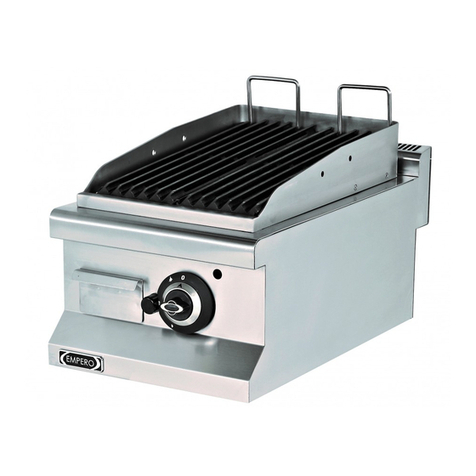
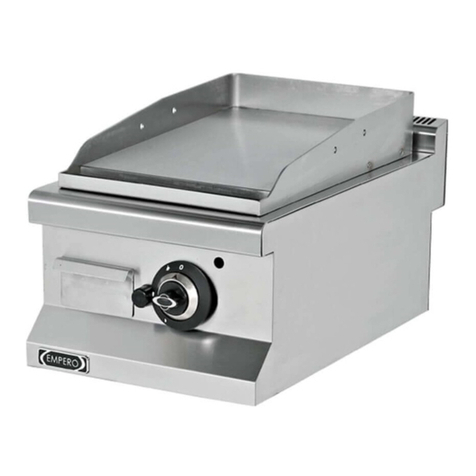
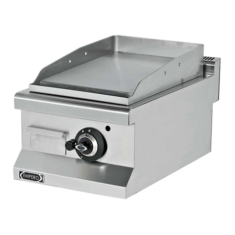
EMPERO EMP.9IG010 User manual

1
GAS GRILLS
CONTENTS
A GENERAL INFORMATION Page 2
A1 PRODUCT DESCRIPTION Page 3
A2 TECHNICAL INFORMATION Page 3
A3 TRANSPORTATION Page 3
A4 UNPACKING Page 4
B INSTALLATION Page 4
C SAFETY INSTRUCTIONS Page 5
D OPERATION Page 6
E CLEANING & MAINTENANCE Page 7
F TROUBLESHOOTING Page 8
G INJECTOR CHANGE AND GAS SETTING Page 9
H GAS CONNECTION IMAGES Page 10
I SPARE PART LIST- EXPLODING DRAWING Page 12

2
GAS GRILLS
A GENERAL INFORMATION
Before installing the appliance, read operation and maintenance instructions
carefully.Wrong installation and part changing may damage the product or may cause
injury on people.These are not in our company’s responsibility to damage the
appliance intentionally,negligence,detriments because of disobeying instructions and
regulations,wrong connections.Unauthorized intervention to appliance invalidates the
warranty.
1. This instruction manual should be kept in a safe place for future reference.
2. Installation should be made in accordance with ordinances and security rules of
that country by a qualified service personnel.
3. This appliance has to be used by trained person.
4. Please turn off the appliance immediately in the event of malfunction or failure.The
appliance should be repaired only by authorized service personnel.Please demand
original spare part.

3
GAS GRILLS
A1 PRODUCT DESCRIPTION
*The Professional Gas Grills,that provides high efficiency has been designed to be used in
industrial kitchens.
Product Code
Dimensions (mm)
Weight (kg)
Packaging
Dimensions (mm)
EMP.9IG010
400x900x285
65
430x1000x590
EMP.9IG020
800x900x285
106
830x1000X590
EMP.9IG022
800x900x285
108
830x1000X590
EMP.7IG010
400X730X285
40
480X800X590
EMP.7IG020
800X730X285
60
830X800X590
EMP.7IG022
800X730X285
60
830X800X590
A2 TECHNICAL INFORMATION
Product
Code
Model
Power
(KW)
Gas
Consumption
(NG)
Gas
Consumption
(LPG)
EMP.9IG010
Gas Grill-Smooth-Cabinet
7
1,0 m³/h
0,7 kg/h
EMP.9IG020
Gas Grill-Smooth-Cabinet
14
1,9 m³/h
1,4 kg/h
EMP.9IG022
Gas Grill-Smooth+Ribbed-
Cabinet
14
1,9 m³/h
1,4 kg/h
EMP.7IG010
Gas Grill-Smooth-Cabinet
6
0,8 m³/h
0,6 kg/h
EMP.7IG020
Gas Grill-Smooth-Cabinet
12
1,5 m³/h
1,1 kg/h
EMP.7IG022
Gas Grill-Smooth+Ribbed-
Cabinet
12
1,5 m³/h
1,1 kg/h

4
GAS GRILLS
A3 TRANSPORTATION
* This appliance can not be moved by hand from area to area. Therefore Use a hauling truck
(forklift or pallet jack) to move the appliance. ( The lifting arms of the of forklift or pallet jack
must reach up to more than half part of t appliance underneath.)
A4 UNPACKING
*Please unpack the package according to the security codes and ordinances of current
country and get rid from the pack.Parts which contacts with food are produced by stainless
steel.All plastic parts are marked by material’s symbol.
*Please check that all the parts of appliance had come completely and if they are damaged or
not during the shipping.
B MONTAJ
*Please place the product to straight and sturdy ground,please take necessary steps against
possibility of overturn.
*Technician who will serve for installation and service for the appliance must be professional
on this subject and must have installation and service licenses by the company.
*Connection to Gas Fitment or any amendment process must be done by authorized person.
*The area where the appliance is must have enough ventilation and vent-hole.
*The appliance must be connected correctly according to local and national gas standards of
your country.
*The appliance gas entrances are indicated with ‘’G’’ label on the body.
*Connection to gas fitment must be done with suitable diameter metal flex pipe and spheric
valve.The spheric valve must be immobilized to a place that is far away from heat and
accessible during the danger.After gas entrance connection done,gas leakages must be
checked.
*According to the datas on appliance information plate,gas and pressure must be adjusted.If
the gas type that is adjusted is not the suitable with gas type that is at installation place,apply
the instructions that is about adjustment of different gas type. (Event :G)
*If the location where gas grills placed is covered with nonflammable heat insulation
material,the distance between them must be 5 cm.Otherwise it should be at least 20 cm.The
appliance shouldn’t be operated under chimney hood.

5
GAS GRILLS
C SAFETY INSTRUCTIONS
*Do not use the appliance in insufficient lighted place.
*Do not touch the moving attachments while the appliance operates.
*Do not install the appliance in the presence of flammable or explosive materials.
*Do not operate the appliance when the machine is empty.
*Do not load so less or more than appliance’s capacity.
*Do not attempt to use the appliance without suitable protective equipments.
*Because of any reason if there is a fire or flame flare where the appliance is
used,turn off all gas valves and electric contactor switch quickly and use fire
extinguisher .Never use water to extinguish the fire.
*If there is gas leakage where the appliance is, .do not fire absolutely and do not use
electric .
*Definitely do not allow to check the sealing with flame.
!
!
!
!
!
!
!
!

6
GAS GRILLS
D OPERATION
*Control Panel;
A : Off Position
B : Lighter Position
C : Full Flame
D: Half Flame
E: Spyhole
F: Lighter
G : Oil Drawer
*Operating;
•According to type of use,make gas entrance connection from behınd the grill.Because the
machine is operated with LPG and NG.
•Turn on the gas valves.
•Press the button at Pilot position before firing to remove the air from gas fitment during
first operation.
•Press the gas grill button and provide pilot position.Fire the pilot with suitable lighter.
•In order to heat thermocouple’s end keep pressing to button after the pilot is fired.
•For desired temperature switch to half or full flame position.
•Operate the grill when it is empty to remove protective oil and place the foods that will be
cooked on the grill.
•Be sure that the oil flows to oil drawer.
•After the operation is completed,switch the gas valve to (0) position.

7
GAS GRILLS
E CLEANING & MAINTENANCE
➢CLEANING AND MAINTENANCE AFTER EVERY USE
•Turn off the gas connection before cleaning.
•Clean the outer surface of the appliance with a wet cloth and chrome shiner.
•Do not use abrasive cleaning chemicals as these can leave harmful residues.
•Do not wash the appliance with pressure water.
•Do not clena the appliance with a materials that may damage chrome material.
•Clean the grills with suitable spatula.
➢PERIODIC CLEANING AND MAINTENANCE
•Maintenance should be done by qualified person.
•These parts ; Gas storage,pilot,thermocouples,taps,burner,lighter and spark plug
cable are not maintained so they need to be changed when they have error.
•Check the gas connection hoses in periodic time.If there is slit,hole..etc,change the
hoses.
•Ventilate the area where the device is in periodic times.

8
GAS GRILLS
F TROUBLESHOOTING
THE APPLIANCE DOESN’T OPERATE
1. Check if the gas connection is done or
not.
2. If there is no gas entrance to pilot,the
appliance is not operated.
3. Check if the injector holes are opened
or not.
4. If the hoses that have gas entrance
lose gas due to slit,hole.etc.,the
appliance is not operated.
THE APPLIANCE DOESN’T COOK WELL
1. Check if it is operated at suitable gas
setting or not.
THE APPLIANCE STOPPED
1. Gas flow is stopped automatically when
the flame is off due to having gas tap
that has safety valve.In this situation
the appliance is not operated.
2. When there is gas leakage,if there is
solenoid gas stopper alarm,gas flow is
stopped and the appliance is not
operated.Ventilate the area through the
agency of vent-hole.
•If cooking at gas grills is not done at suitable quality
•If any function of security doesn’t work
➢Do not use the appliance.
*If these problems are still going on,contact with our authorized services.

9
GAS GRILLS
G INJECTOR CHANGE AND GAS SETTING
GAS GRILL BURNER - INJECTOR CHANGE CHART
Gas Group
Gas
9IG-7IG
Pilot
Injector mm
Injector mm
2
G20
2,15
0,41
G25
2,15
0,41
3
G30
30 mbar
1,35
0,22
50 mbar
1,6
0,20
G31
37 mbar
1,35
0,22
30 mbar
1,3
0,20
Change of Burner Injector;
1. Rip off the injector at the entrance of burner with a suitable tool.
2. Change A injector by paying attention to the datas at chart with suitable injector.
(Image 1)
3. Adjust the burner entrance setting (F) by loosening ‘B’ bolt and moving the valve to
forward-back. (Image 2)
4. Change C injector by paying attention to the datas at chart with suitable injector.For
this it is enough to take off ‘D’ fitting and pull the gas pipe to down. (Image 3)
Setting of Half Flame;
1. Remove the tap button and set by turning tap half flame screw (K) with suitable
screwdriver.(Image 4) Turn it to left for transformation from LPG to N.G,turn it right for
transformation from N.G to LPG.
2. After this process,operate the appliance and set it not to be deflated during transition
from full flame to half flame

10
GAS GRILLS
H GAS CONNECTION IMAGES
Image-1
Image-2
Image-1

11
GAS GRILLS
H GAS CONNECTION IMAGES
Image-3
Image -4

12
GAS GRILLS
I SPARE PART LIST-EXPLODING DRAWING
EMP.9IG010-7IG010

13
GAS GRILLS
I SPARE PART LIST-EXPLODING DRAWING
PRODUCT CODE: EMP.7IG010
NO
PRODUCT NAME
P.CODE
1
BASE FRAME
Y.EMP.7IG010.001
2
FEET
Y.EMP.7IG010.002
3
SPARKING PLUG+CABLE
Y.EMP.7IG010.003
4
DRAWER
Y.EMP.7IG010.004
5
INJECTOR GROUP
Y.EMP.7IG010.005
6
BUTTON BUFFER
Y.EMP.7IG010.006
7
PILOT
Y.EMP.7IG010.007
8
GAS TANK
Y.EMP.7IG010.008
9
BUTTON
Y.EMP.7IG010.009
10
LIGHTER
Y.EMP.7IG010.010
11
GAS TAP
Y.EMP.7IG010.011
12
TOP PLATINE
Y.EMP.7IG010.012
13
BURNER
Y.EMP.7IG010.013
14
THERMO PART
Y.EMP.7IG010.014
15
BURNER BRACKET
Y.EMP.7IG010.015
16
FLAME SPREADER
Y.EMP.7IG010.016
17
FLEX HOSE 60CM
Y.EMP.7IG010.017

14
GAS GRILLS
I SPARE PART LIST-EXPLODING DRAWING
PRODUCT CODE: EMP.9IG010
NO
PRODUCT NAME
P.CODE
1
BASE FRAME
Y.EMP.9IG010.001
2
FEET
Y.EMP.9IG010.002
3
SPARKING PLUG+CABLE
Y.EMP.9IG010.003
4
DRAWER
Y.EMP.9IG010.004
5
INJECTOR GROUP
Y.EMP.9IG010.005
6
BUTTON BUFFER
Y.EMP.9IG010.006
7
PILOT
Y.EMP.9IG010.007
8
GAS TANK
Y.EMP.9IG010.008
9
BUTTON
Y.EMP.9IG010.009
10
LIGHTER
Y.EMP.9IG010.010
11
GAS TAP
Y.EMP.9IG010.011
12
TOP PLATINE
Y.EMP.9IG010.012
13
BURNER
Y.EMP.9IG010.013
14
THERMO PART
Y.EMP.9IG010.014
15
BURNER BRACKET
Y.EMP.9IG010.015
16
FLAME SPREADER
Y.EMP.9IG010.016
17
FLEX HOSE 80CM
Y.EMP.9IG010.017

15
GAS GRILLS
I SPARE PART LIST-EXPLODING DRAWING
EMP.9IG020-7IG020

16
GAS GRILLS
I SPARE PART LIST-EXPLODING DRAWING
PRODUCT CODE: EMP.9IG020
NO
PRODUCT NAME
P.CODE
1
BASE FRAME
Y.EMP.9IG020.001
2
FEET
Y.EMP.9IG020.002
3
SPARKING PLUG+CABLE
Y.EMP.9IG020.003
4
DRAWER
Y.EMP.9IG020.004
5
INJECTOR GROUP
Y.EMP.9IG020.005
6
BUTTON BUFFER
Y.EMP.9IG020.006
7
PILOT
Y.EMP.9IG020.007
8
GAS TANK
Y.EMP.9IG020.008
9
BUTTON
Y.EMP.9IG020.009
10
LIGHTER
Y.EMP.9IG020.010
11
GAS TAP
Y.EMP.9IG020.011
12
TOP PLATINE
Y.EMP.9IG020.012
13
BURNER
Y.EMP.9IG020.013
14
THERMO PART
Y.EMP.9IG020.014
15
BURNER BRACKET
Y.EMP.9IG020.015
16
FLAME SPREADER
Y.EMP.9IG020.016
17
FLEX HOSE 80CM
Y.EMP.9IG020.017

17
GAS GRILLS
I SPARE PART LIST-EXPLODING DRAWING
PRODUCT CODE: EMP.7IG020
NO
PRODUCT NAME
P.CODE
1
BASE FRAME
Y.EMP.7IG020.001
2
FEET
Y.EMP.7IG020.002
3
SPARKING PLUG+CABLE
Y.EMP.7IG020.003
4
DRAWER
Y.EMP.7IG020.004
5
INJECTOR GROUP
Y.EMP.7IG020.005
6
BUTTON BUFFER
Y.EMP.7IG020.006
7
PILOT
Y.EMP.7IG020.007
8
GAS TANK
Y.EMP.7IG020.008
9
BUTTON
Y.EMP.7IG020.009
10
LIGHTER
Y.EMP.7IG020.010
11
GAS TAP
Y.EMP.7IG020.011
12
TOP PLATINE
Y.EMP.7IG020.012
13
BURNER
Y.EMP.7IG020.013
14
THERMO PART
Y.EMP.7IG020.014
15
BURNER BRACKET
Y.EMP.7IG020.015
16
FLAME SPREADER
Y.EMP.7IG020.016
17
FLEX HOSE 60CM
Y.EMP.7IG020.017

18
GAS GRILLS
I SPARE PART LIST-EXPLODING DRAWING
EMP.9IG022-7IG022

19
GAS GRILLS
I SPARE PART LIST-EXPLODING DRAWING
PRODUCT CODE: EMP.9IG022
NO
PRODUCT NAME
P.CODE
1
BASE FRAME
Y.EMP.9IG022.001
2
FEET
Y.EMP.9IG022.002
3
SPARKING PLUG+CABLE
Y.EMP.9IG022.003
4
DRAWER
Y.EMP.9IG022.004
5
INJECTOR GROUP
Y.EMP.9IG022.005
6
BUTTON BUFFER
Y.EMP.9IG022.006
7
PILOT
Y.EMP.9IG022.007
8
GAS TANK
Y.EMP.9IG022.008
9
BUTTON
Y.EMP.9IG022.009
10
LIGHTER
Y.EMP.9IG022.010
11
GAS TAP
Y.EMP.9IG022.011
12
TOP PLATINE
Y.EMP.9IG022.012
13
BURNER
Y.EMP.9IG022.013
14
THERMO PART
Y.EMP.9IG022.014
15
BURNER BRACKET
Y.EMP.9IG022.015
16
FLAME SPREADER
Y.EMP.9IG022.016
17
FLEX HOSE 80CM
Y.EMP.9IG022.017

20
GAS GRILLS
I SPARE PART LIST-EXPLODING DRAWING
PRODUCT CODE: EMP.7IG022
NO
PRODUCT NAME
P.CODE
1
BASE FRAME
Y.EMP.7IG022.001
2
FEET
Y.EMP.7IG022.002
3
SPARKING PLUG+CABLE
Y.EMP.7IG022.003
4
DRAWER
Y.EMP.7IG022.004
5
INJECTOR GROUP
Y.EMP.7IG022.005
6
BUTTON BUFFER
Y.EMP.7IG022.006
7
PILOT
Y.EMP.7IG022.007
8
GAS TANK
Y.EMP.7IG022.008
9
BUTTON
Y.EMP.7IG022.009
10
LIGHTER
Y.EMP.7IG022.010
11
GAS TAP
Y.EMP.7IG022.011
12
TOP PLATINE
Y.EMP.7IG022.012
13
BURNER
Y.EMP.7IG022.013
14
THERMO PART
Y.EMP.7IG022.014
15
BURNER BRACKET
Y.EMP.7IG022.015
16
FLAME SPREADER
Y.EMP.7IG022.016
17
FLEX HOSE 60CM
Y.EMP.7IG022.017
This manual suits for next models
5
Table of contents
Other EMPERO Grill manuals
Popular Grill manuals by other brands

Thermos
Thermos 461644304 use and care manual
EURO
EURO EA120BTSX User manual and installation instructions
Char-Broil
Char-Broil Heatwave 2218932 Guide

Jackson Grills
Jackson Grills Classic PG-50403SRL Assembly, care & use manual

Texsport
Texsport 15100 instructions

Broil King
Broil King Imperial XLS 9578-84 Assembly manual & parts list
