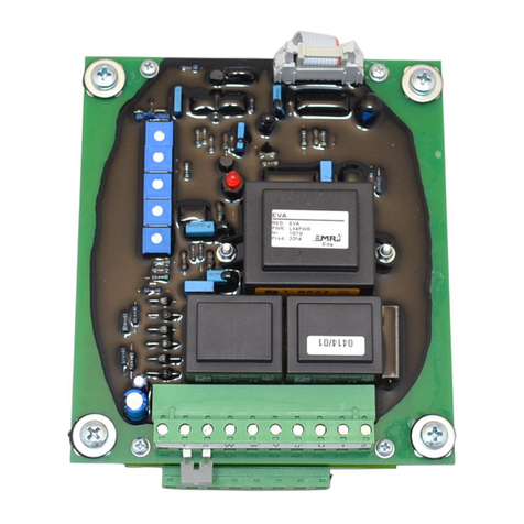
EMRI LX4 User manual

LX4
Voltage regulator for generators
Instruction Manual V3.1.1
Product version V3.1

Manual V3.1.1 Page 2 of 36
Warnings
The manual does not cover all technical details of the product. Specifications may be modified
by the manufacturer without notice. For further information, the manufacturer should be
contacted.
WARNING
The system should not be installed, operated, serviced or
modified except by qualified personnel who understand
the danger of electric shock hazards and have read and
understood the user instructions
.
ELECTRICAL HAZARDOUS VOLTAGES
DANGEROUS DO NOT OPERATE WHEN
NOT FAMILIAR WITH GENERATORS
WARNING
Dangerous voltages are present at the voltage regulator
board. Accidental contact with live conductors could result
in serious electrical shock or electrocution.
Disconnect the power source before making repairs,
connecting test instruments, or removing or making
connections to the voltage regulator or generator.
WARNING
Never work on a LIVE generator. Unless there is another
person present who can switch off the power supply or
stop the engine
WARNING
Due to liability reasons, EMRI products may not be used,
applied or commissioned in equipment residing under law
of the United States of America or Canada. Neither may
EMRI products be applied or commissioned by any
person residing under law of the United States of America
or Canada.

Manual V3.1.1 Page 3 of 36
Table of contents
Part 1/2
1. Introduction
1.0 General description 5
1.1 AVR Layout 5
1.2 Absolute maximum ratings 6
1.3 ommissioning information 6
2. Installation
2.0
Interfaces overview 7
2.1 Adjustments overview 8
2.2 Terminals overview 9
2.3 Electrical characteristics 10
3. Operation and maintenance
3.0 AVR status 11
3.1 Modes of control 11
3.1.0 Idle
11
3.1.1 Build-up
11
3.1.2 Voltage control
12
3.2 Setpoint limiting 13
3.2.0 Introduction
13
3.2.1 Excitation current limiting
14
3.2.2 Generator over temperature limiting
15
3.2.3 Underspeed limiting
16
3.3 Special functions 17
3.3.0 Self Excitation
17
3.4 AN bus 18
3.4.1 Introduction
18
3.4.2 AN status LED
18
3.4.3 AN heartbeat
18
3.4.4 AN AVR measurements & status
19
3.4.5 AN control
20
4 Protections and diagnose
4.1 LED error codes 21
4.2 Protections 21
4.2.0
Over excitation protection
22
4.2.1 Generator over temperature protection
23
4.2.2 AVR over temperature protection
24
4.2.3 Phase loss / phase sequence protection
25
4.2.4 Over voltage protection 110%
26
4.2.5 Over voltage protection 125%
27

Manual V3.1.1 Page 4 of 36
Table of contents
Part 2/2
5 Settings and adjustments
5.1 Generator voltage 28
5.2 P & I stability 28
5.3 Underspeed frequency 28
5.4 Dipswitch settings 29
5.5 T.Disable header 30
5.6 SE header 30
5.7 EXT.POT. header 30
5.8 AN Termination header 30
5.9 Factory settings 31
6 Wiring diagrams
6.1 Wiring diagram single auxiliary supply winding 32
6.2 Wiring diagram double auxiliary supply winding 33
6.3 Wiring diagram transformer supply 34
ppendix
General Installation information 35

Manual V3.1.1 Page 5 of 36
1. INTRODUCTION
1.0 General description
This manual contains instructions for installing, operating and maintaining the LX4
Automatic Voltage Regulator (AVR).
1.1 AVR Layout
The AVR is protected against environmental influences by a PUR coating. Prefabricated links
are provided for T.Disable, EXT.POT and CAN termination
WVUS2S1T1 T2LH1 LH2- +
F
on dip
12 3 4
Status
LED V P I D
JTAG
Int rfac
EME RD200.1
Firmware: V1.x
Nr: 1234
Hardware: V1.x
Prod: 0106 Ede NL
CAN Int rfac
CAN LED
T.Disabl
CAN T rmination
FUSE
LHGND NC
LH3 LH4
SE
EXT.
POT.
28 23130,00
9,00
115,00
9,00
Fig 1. AVR layout
Max AVR h ight: 60 mm
Dim nsions in mm

Manual V3.1.1 Page 6 of 36
1.2 Absolute maximum ratings
Symbol
Param t r
Condition
Min.
Max.
Unit
U
,
V
,
W
Voltage sensing input
< 30 s.
-
500
V
AC
+,
-
AVR field current
Continuous
< 10 s.
-
-
3
A
DC
A
DC
LH1
-
LH2,
LH3-LH4
Supply input
1 phase connected (dc
-
400Hz)
3 phases connected (dc-400Hz)
20
15
100
100
V
V
R
field
Field resistance
@ 100 V
LH1-2 LH3-4
(rms)
@ 0 V
LH1
-
2 LH3
-
4
(rms)
10
-
-
Ω
Ω
T
AMB
Operating temperature
95 % RHD non condensing
-
20
+70
°C
T
STG
St
orage temperature
95 % RHD non condensing
-
20
+85
°C
S1,S2
Unused terminals
EXT. POT.
External Volt adjust
-
10
k
Ω
FUSE
Fuse rating
Time delay
4
AT
Table 1. Absolute maximum ratings
1.3 Commissioning information
The system should not be installed, operated, serviced or modified except by qualified
personnel who understand the danger of electric shock hazards and have read and
understood the user instructions.
Defects in the generator or AVR may cause consequential loss. Precautions must be taken to
prevent this from occurring.
Never work on a LIVE generator. Unless there is another person present who can switch off
the power supply or stop the prime mover.
Dangerous voltages are present at the voltage regulator board. Accidental contact with live
conductors could result in serious electrical shock or electrocution.
Disconnect the power source before making repairs, connecting test instruments or removing
or making connections to the voltage regulator.
The unit should be installed with respect to the environmental specifications as well as the
rules mentioned in the General installation information.
For safety reasons the Voltage level potentiometer is best turned completely counter
clockwise in order to start at the lowest possible voltage.

Manual V3.1.1 Page 7 of 36
2. INSTALLATION
For a complete wiring diagram refer to chapter 6: Wiring diagrams.
2.0
Interfaces overview
tatus
LED
JTAG
Interface
CAN Interface
CAN LED
LHGND NC
Fig 2. Interfaces overview
Symbol
Description
Notes
Status LED AVR control mode & Error diagnostics See Table 6 and 11
CAN LED CAN bus control mode & Error diagnostics See Table 7
CAN Interface.L CAN bus low wire
CAN Interface.H CAN bus high wire
CAN Interface.GND CAN bus ground
CAN Interface.NC Not connected
JTAG Interface Maintenance port
Table 2. Interfaces

Manual V3.1.1 Page 8 of 36
2.1 Adjustments overview
F
on dip
12 3 4
V P I D
Fig 3. Adjustments overview
Symbol
Description
Notes
V Generator voltage setpoint
P Proportional gain setpoint
I Integral time setpoint
D Unused Should be in CCW position
F Underspeed setpoint
Dipswitch 1 Sensing voltage selection Off = 400V
ac
On = 230V
ac
Dipswitch 2 Phaseloss protection Off = disabled On = enabled
Dipswitch 3 Control mode selection Off = Constant voltage On = VPH
Dipswitch 4 Overexcitation threshold Off = 2A On = 4A
Table 3. Adjustments
DO NOT CH NGE DIPSWITCH
SETTINGS DURING OPER TION

Manual V3.1.1 Page 9 of 36
2.2 Terminals overview
WVU21T1 T2LH1 LH2- +
T.Disable
CAN Termination
LH3 LH4
E
EXT.
POT.
Fig 4. Terminals overview
Symbol
Description
Notes
U, V, W Voltage sensing input phase sequence U→V→W
S1, S2 Unused terminals
T1, T2 Temperature sensor input KTY84-130, PTC or Clixon sensor
LH1, LH2
LH3, LH4
Supply inputs For self excitation, the auxiliary supply
winding must be connected to LH3-LH4
+, - Field excitation output
SE Self Excitation link
(Caution: High voltage)
Never fit or remove link while generator is in
operation
Shorting SE enables self excitation.
EXT. POT. External voltage adjust input 10
k
Ω potentiometer
T.Disable Disables T1 – T2 sensing Shorting T.Disable disables temperature
protection
CAN Termination CAN bus termination link Shorting enables 120 Ohm bus termination
Table 4. Terminals

Manual V3.1.1 Page 10 of 36
2.3 Electrical characteristics
Symbol
Param t r
Condition
Min.
Max.
Unit
U, V, W
Voltage sensi
ng input
5
0
-
0
Hz
20
480
V
AC
+
,
-
AVR field current
-
3
A
DC
LH1
–
LH2,
LH3 – LH4
Supply input
dc
-
400 Hertz
20
100
V
AC
R
field
Field resistance
10
-
Ω
T
AMB
Operating temperature
95 % RHD non condensing
0
+70
°C
T
STG
Storage temperature
95 % RHD
non condensing
-
20
+85
°C
S1
–
S2
Unused terminals
EXT. POT.
External Volt adjust
10k
Ω potentiometer
0
10
k
Ω
FUSE
Fuse rating
Ceramic,
Time delay
4
AT
Table 5. Electrical characteristics
Stresses above those listed under “Absolute Maximum Ratings” may cause permanent damage to the
device. This is a stress rating only and functional operation of the device at those or any other conditions above
those indicated in the operation listings of this specification is not implied. Exposure to maximum rating conditions
for extended periods may affect device reliability and lifetime.

Manual V3.1.1 Page 11 of 36
3. Operation and maintenance
3.0 AVR Status LED
The AVR’s mode of control is indicated by the status LED. The options are depicted in table 6.
Table 6. AVR status
3.1 Modes of control
3.2.0 Idle
When a supply is connected to the AVR but the generator frequency is below 25Hz, the AVR
enters idle mode. During idle mode field excitation is inhibited however all protections remain
functional.
3.1.1 Build-up
When the generator frequency rises above 25Hz, the AVR enters the build up mode. The
generator voltage is ramped up to the voltage setpoint. When the generator voltage is close to
the desired nominal value, the status led signals continuous green. Diagram 1 shows the
sequence of events.
Diagram 1. Build up

Manual V3.1.1 Page 12 of 36
3.1.2 Voltage control
When dipswitch 3 is in off position, the AVR performs constant voltage control after finishing
the build up mode. The voltage/ frequency characteristic is depicted in diagram 2.
Below the underspeed frequency, set by potentiometer F, the generator voltage is controlled
according a Volt per Hertz ramp. Below 25Hz the AVR control mode returns to idle and
excitation is stopped. As a consequence the generator voltage will then drop to the residual
voltage level. For a detailed description of potentiometer F see chapter 5.4.
Diagram 2. Constant Voltage control
When dipswitch 3 is in on position, the AVR performs Volt per Hertz control after finishing the
build up mode. The voltage/ frequency characteristic is depicted in diagram 3.
Diagram 3. Volt per Hertz Control

Manual V3.1.1 Page 13 of 36
3.2 Setpoint limiting
3.2.0 Introduction
The AVR is equipped with both limiting functions and protections.
The limiting functionality lowers the voltage- or excitation setpoint if a certain threshold is
exceeded. When the measured quantity no longer exceeds the threshold, the setpoint is
increased again. This enables the AVR to recover from the situation.
The protections also lower the voltage setpoint, upon exceeding a certain threshold. However
Recovery is only possible by resetting the AVR. This is accomplished by interrupting the AVR
supply (LH1-LH2 and LH3-LH4) for at least 5 seconds. In case an auxiliary supply winding is
used this may be accomplished by stopping the generator.
When a protection is triggered the voltage setpoint is decreased to a fixed level of 95V.
Keep in mind that the actual generator voltage may larger than 95V due to the generator’s
residual magnetism.
For a detailed description of all protections refer to chapter 4.

Manual V3.1.1 Page 14 of 36
3.2.1 Excitation current limiting
When the excitation current level, selected by dipswitch 4, is exceeded for more than 5
second, the AVR controls the excitation current to the selected level.
Excitation current control is visualized by the status LED signalling continuous orange.
When the excitation current decreases below the selected threshold again, for more than 5
second, voltage control is resumed. The AVR ramps back to the voltage setpoint, while
signalling a orange blinking status LED. When the generator voltage is close to the desired
nominal value, the status led becomes continuous green.
Diagrams 5 shows a sequence of events for diagnosis purposes in case of excitation limiting.
Diagram 5. Excitation limiting

Manual V3.1.1 Page 15 of 36
3.2.2 Generator over temperature limiting
The generator temperature may be sensed either by a clixon, PTC or KTY84-130 sensor
connected to terminals T1-T2. The over temperature limiting and protection can be disabled
by omitting the temperature sensor and shorting link T.Disable
If a clixon or PTC is connected no absolute temperature can be measured, only the exceeding
of a threshold. In this case the generator over temperature protection is triggered
simultaneously with the over temperature limiting function. This causes the AVR to decrease
the voltage setpoint to 95V. The generator over temperature protection is described in 4.2.1.
If a KTY84-130 sensor is connected and the generator temperature exceeds 160ºC for more
than 5 seconds, the AVR decreases the voltage level. The voltage level is decreased linear,
inverse proportional to the temperature transgression by 1.5V/ºC.
Active voltage limiting is visualized by the status LED signalling continuous orange.
When the generator temperature decreases, voltage is increased again until the nominal
voltage. When the generator voltage is close to the desired nominal voltage, the status led
becomes continuous green again.
Diagram 6 shows a sequence of events for diagnosis purposes in case of generator over
temperature limiting.
Diagram 6. Over temperature limiting

Manual V3.1.1 Page 16 of 36
3.2.3 Underspeed limiting
The goal of the underspeed limiting is to prevent damage to the generator caused by
overexcitation. When the generator frequency drops below the underspeed setpoint,
F
underspeed
, the generator voltage is decreased linear, proportional to the generator frequency.
The underspeed setpoint is set by potentiometer F, as is described in 5.4.
Active underspeed limiting is visualized by the status LED signalling continuous orange,
however only when the constant voltage control mode is selected (dipswitch 3 = ‘ on’).
In case the generator frequency drops below 25Hz excitation is stopped completely and the
AVR control mode becomes idle. This is visualized by a green blinking status LED.
Diagrams 7 shows a sequence of events for diagnosis purposes in case of underspeed
limiting during constant voltage control.
Diagram 7. VPH underspeed limiting

Manual V3.1.1 Page 17 of 36
3.3 Special functions
3.3.0 Self Excitation
When the AVR supply voltage, connected to LH1-2 and LH3-4, is insufficient to supply the
AVR, self excitation can be used. Self excitation is enabled by shorting the SE terminal.
The self excitation circuit redirects the AVR supply voltage to the generator’s exciter field
uncontrolled, bypassing the internal controller. This field flashing causes the generators flux to
increase, amplifying the supply voltage.
When the supply voltage has increased to a level sufficient to supply the AVR, the self
excitation circuit is disabled again. Hereafter, the AVR’s internal controller builds up the
generator voltage.
Diagram 8 shows a sequence of events with enabled self excitation, for diagnosis purposes.
Caution:
Never fit or remove the SE link when the generator is operation.
This is a live conductor, contact can result in serious electrical shock.
Diagram 8. Self Excitation

Manual V3.1.1 Page 18 of 36
3.4
CAN-bus
3.4.1 Introduction
The AVR is equipped with a CAN bus interface. The CAN interface enables the user to obtain
detailed information about the AVR status, measured quantities and to adjust AVR control
setpoints.
The interface complies with CAN specification 2.0B. The AVR communication operates at a
transfer rate of 250kBit/s and uses standard frame (11-bit) message identifiers.
3.4.2 CAN status LED
The CAN bus status is indicated by the CAN status LED. The options are depicted in table 7.
Table 7. CAN status
3.4.3 CAN heartbeat
The AVR sends a heartbeat signal when the AVR is powered. This signal may be used to
assess the proper functioning of the CAN bus communication.
The heartbeat consists of a message with ID 0x70A and is sent every 500ms. The message
content is 1 byte long and alternating 0x05 or 0x85 .
H artb at
ID:0x70A
Byt
D scription
Valu
R marks
0
Alternating heartbeat
0x05 ~ 0x85
Table 8. CAN heartbeat

Manual V3.1.1 Page 19 of 36
3.4.4 CAN AVR measurements & status
When the AVR is powered a message containing AVR measurements and the present AVR
status is sent. The message with ID 0x18A is sent every 500ms. The definition of the 8 byte
content is described in table 9
AVR m asur m nts & status
ID:0x18A
Byt
D scription
Valu
Unit
R marks
0
Gener
ator voltage
0
-
255
V
Phase
-
Neutral
1
Excitation current ratio
0
-
100
%
(Byte 5 / Byte 3) * 100%
2
Generator temperature
0
-
255
ºC
3
Excitation current
0
-
255
0.01A
4
Generator frequency
0
-
255
0.5
Hz
5
Excitation current setpoint
0
-
255
0.01A
Statu
s AVR
Bitwise AVR statusregister
bit 0
Generator current limiting
1
-
0
bit
1 = active
bit 1
Excitation current limiting
1
-
0
bit
1 = active
bit 2
Over temperature generator limiting
1
–
0
bit
1 = active
bit 3
Over temperature AVR limiting
1
–
0
bit
1 = active
bit 4
Underspeed limiting
1
–
0
bit
1 = active
bit 5
Overvoltage 440V protection
1
–
0
bit
1 = triggered
bit
Overvoltage 500V protection
1
–
0
bit
1 = triggered
bit 7
Phaseloss protection
1
–
0
bit
1 = triggered
7
AVR temperature
0
-
255
ºC
Measured at MCU
Table 9. CAN measurements & status

Manual V3.1.1 Page 20 of 36
3.4.5 CAN control
When the AVR is powered it is possible to obtain remote control over the AVR voltage setpoint
and excitation limit setpoint.
To realize CAN control a message with ID 0x20A must be sent at least every 1 seconds
complying with the content definition described in table 10.
When CAN control is activated, but the AVR has not received a valid control message for the
last 1 seconds, CAN control is automatically disabled and normal AVR control is resumed.
Active CAN control is visualized by the CAN status LED signalling continuous orange.
Be aware that when the user enables CAN control over the voltage and/or excitation setpoints,
adjustments to the respective potentiometers on the AVR will have no immediate effect. The
adjustments will only then be effective when CAN control is disabled and AVR control is
resumed again.
CAN control
ID:0x20A
Byt
D scription
Valu
Unit
R marks
0
Generator voltage setpoint
0
-
255
V
Phase
-
Neutr
al
1
Excitation current ratio setpoint
0
-
100
%
Derived from
dipswitch 4 setting
2
-
-
-
not used
3
-
-
-
not used
4
CAN
control
Bitwise
CAN
commandregister
bit 0
Activate CAN voltage setpoint
1
-
0
bit
1 = active
bit 1
-
0
bit
not used
bit 2
-
0
bit
not used
bit 3
-
0
bit
not used
bit 4
Activate CAN excitation ratio setpoint
1
–
0
bit
1 = active
bit 5
-
0
bit
not used
bit
-
0
bit
not used
bit 7
-
0
bit
not used
5
-
-
-
not used
-
-
-
not used
7
-
-
not used
Table 10. CAN control
Table of contents
Other EMRI Controllers manuals
