9 Configuration
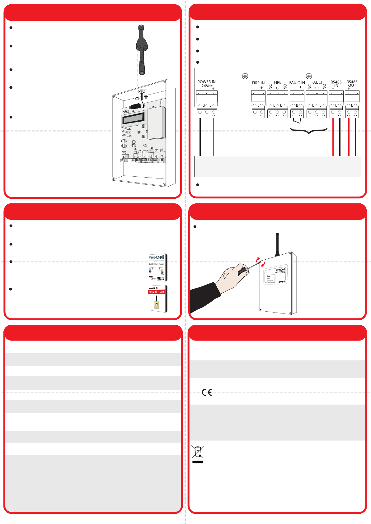
7 Aerial installation 8 Connection wiring
Regulatory informationSpecification
Cables should only be passed via the access points available.
Flame retardant cable glands should be used.
DO NOT leave excess cable in the RNC.
DO NOT earth the enclosure box.
AUX
24 VDC
- +
OUT IN
+ - + -
Taktis control panel
Once connections are made, apply power to the control
panel.
Operating temperature -10 to 55 °C
Storage temperature 5 to 30 °C
Humidity 0 to 95% non-condensing
IP rating IP54
Operating voltage 75 mA at 24 VDC
Operating frequency 458 MHz
Output transmitter
power 500 mW
Dimensions (W x H x D) 156 x 228 x 48 mm
Weight 0.65 kg
Application Indoor Use Only
EN300-220
EN301-489
EN60950
Carrier Manufacturing Polska Sp. Z o.o. Ul.
Kolejowa 24. 39-100 Ropczyce, Poland
Manufacturer
Year of
manufacture See devices serial number label
2012/19/EU (WEEE directive):
Products marked with this symbol cannot be
disposed of as unsorted municipal waste in the
European Union. For proper recycling, return
this product to your local supplier upon
purchase of equivalent new equipment, or
dispose of it at designated collection points.
For more information see www.recyclethis.info
European Union
directives
EMS declares that device is in compliance with
Directive 2014/53/EU. The full text of the EU
declaration of conformity is available at the
following internet address:
www.emsgroup.co.uk
Complies with
Programming is only necessary if the RNC, when powered
displays ‘Unprogrammed’.
The RNC’s programming is configured within the menu structure
of the RNC.
If the RNC is displaying a fault, re-check wiring
then refer to the ‘RNC For Taktis Programming
Manual’ (MK280) for full details.
(Free to download from www.emsgroup.co.uk)
Refer to the ‘RNC For Taktis Quick Start Guide’
(MK282) for programming information. These
details can also be found on the RNC lid.
10 Close RNC
Refit the RNC lid to complete the installation.
Refit the previously removed aerial fly
lead connection.
Fit the aerial to the BNC connection at
the top of the unit and twist clockwise to
secure into position.
Fit the aerial anti-tamper shroud over
the aerial.
Secure the shroud, by tightening the
two thumb nuts onto the
bottom of the aerial shroud as
shown.
Note: If fitting a remote aerial
to the RNC, replace the
standard aerial shown.
Fault input / output
for remote fault
monitoring / remote
PSU (optional)
NETWORK
NO
©2022 EMS Ltd. All rights reserved. Page 2 of 2 MK281-99 Iss 2 20/01/2022 AJM


