Rotex HPSU compact 508 User manual

For the operator
ROTEX HPSU compact
Solar tank with integrated interior heat
pump unit
Instruction manual
Types
HPSU compact 508
HPSU compact 516
HPSU compact 508H
HPSU compact 516H
Serial number
Customer
GB
Edition 04/2011

List of contents
2BA ROTEX HPSU compact 2 - 04/2011
1 Safety . . . . . . . . . . . . . . . . . . . . . . . . . . . . . . . . . . . . . . . . . . . . . . . . . . . . . . . . . . . . . . . . . . . . . . . . . . . . . . . . . . . 4
1.1 Refer to the manual . . . . . . . . . . . . . . . . . . . . . . . . . . . . . . . . . . . . . . . . . . . . . . . . . . . . . . . . . . . . . . . . . . . . . . . . . . . . . . . . . . . . . . 4
1.2 Warning signs and explanation of symbols . . . . . . . . . . . . . . . . . . . . . . . . . . . . . . . . . . . . . . . . . . . . . . . . . . . . . . . . . . . . . . . . . . . . . 4
1.3 Avoid danger . . . . . . . . . . . . . . . . . . . . . . . . . . . . . . . . . . . . . . . . . . . . . . . . . . . . . . . . . . . . . . . . . . . . . . . . . . . . . . . . . . . . . . . . . . . 5
1.4 Proper use . . . . . . . . . . . . . . . . . . . . . . . . . . . . . . . . . . . . . . . . . . . . . . . . . . . . . . . . . . . . . . . . . . . . . . . . . . . . . . . . . . . . . . . . . . . . . 5
1.5 Instructions for operating safety . . . . . . . . . . . . . . . . . . . . . . . . . . . . . . . . . . . . . . . . . . . . . . . . . . . . . . . . . . . . . . . . . . . . . . . . . . . . 6
2 Product description . . . . . . . . . . . . . . . . . . . . . . . . . . . . . . . . . . . . . . . . . . . . . . . . . . . . . . . . . . . . . . . . . . . . . . . . 7
2.1 Brief description. . . . . . . . . . . . . . . . . . . . . . . . . . . . . . . . . . . . . . . . . . . . . . . . . . . . . . . . . . . . . . . . . . . . . . . . . . . . . . . . . . . . . . . . . 7
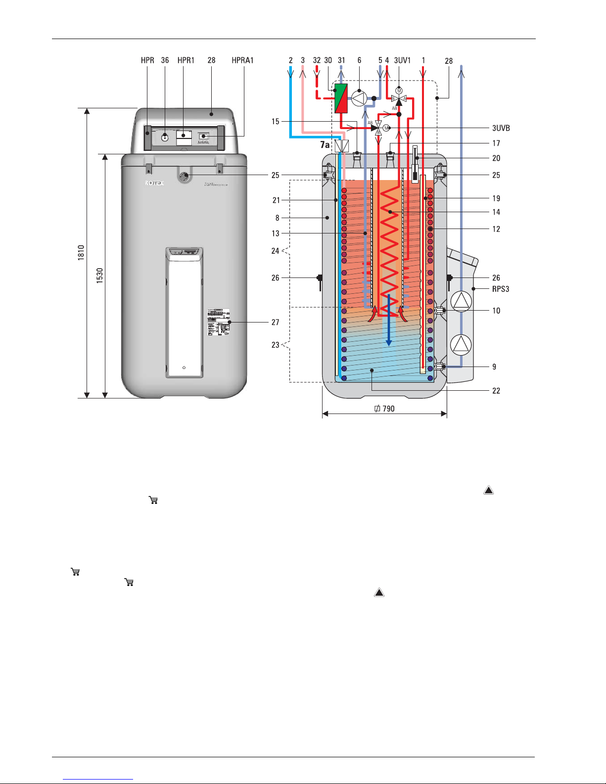
2.2 Design and components . . . . . . . . . . . . . . . . . . . . . . . . . . . . . . . . . . . . . . . . . . . . . . . . . . . . . . . . . . . . . . . . . . . . . . . . . . . . . . . . . . . 8
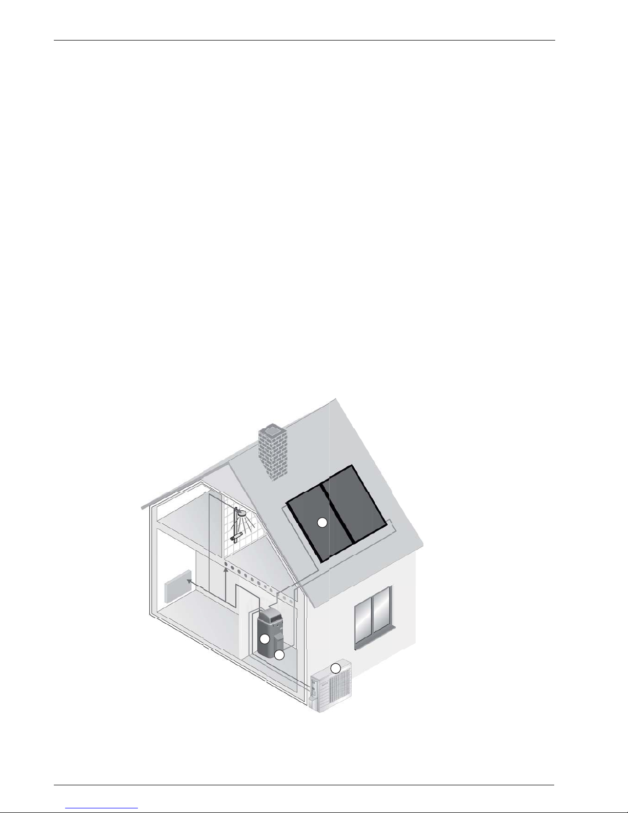
2.2.1 System overview . . . . . . . . . . . . . . . . . . . . . . . . . . . . . . . . . . . . . . . . . . . . . . . . . . . . . . . . . . . . . . . . . . . . . . . . . . . . . . . . . . . . . 8
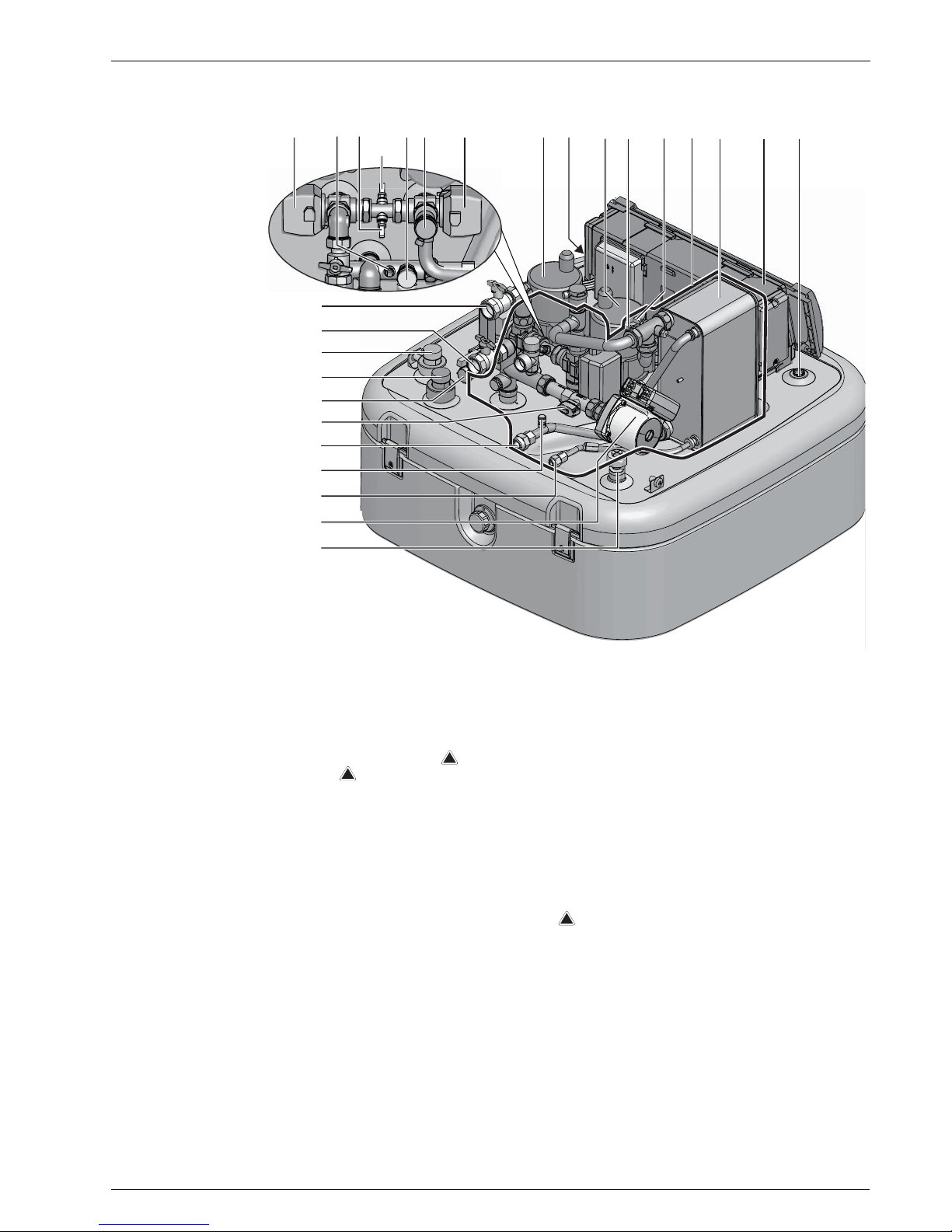
2.2.2 HPSU compact. . . . . . . . . . . . . . . . . . . . . . . . . . . . . . . . . . . . . . . . . . . . . . . . . . . . . . . . . . . . . . . . . . . . . . . . . . . . . . . . . . . . . . . 9
3 Operation. . . . . . . . . . . . . . . . . . . . . . . . . . . . . . . . . . . . . . . . . . . . . . . . . . . . . . . . . . . . . . . . . . . . . . . . . . . . . . . . 11
3.1 Instructions . . . . . . . . . . . . . . . . . . . . . . . . . . . . . . . . . . . . . . . . . . . . . . . . . . . . . . . . . . . . . . . . . . . . . . . . . . . . . . . . . . . . . . . . . . .11
3.2 Main display and operating elements . . . . . . . . . . . . . . . . . . . . . . . . . . . . . . . . . . . . . . . . . . . . . . . . . . . . . . . . . . . . . . . . . . . . . . . . 11
3.3 Main control unit (HPR1) . . . . . . . . . . . . . . . . . . . . . . . . . . . . . . . . . . . . . . . . . . . . . . . . . . . . . . . . . . . . . . . . . . . . . . . . . . . . . . . . . 12
3.3.1 Operating and display components. . . . . . . . . . . . . . . . . . . . . . . . . . . . . . . . . . . . . . . . . . . . . . . . . . . . . . . . . . . . . . . . . . . . . . . 12
3.3.2 Basic functions and operating modes . . . . . . . . . . . . . . . . . . . . . . . . . . . . . . . . . . . . . . . . . . . . . . . . . . . . . . . . . . . . . . . . . . . . . 16
3.3.3 Switching the system on and off . . . . . . . . . . . . . . . . . . . . . . . . . . . . . . . . . . . . . . . . . . . . . . . . . . . . . . . . . . . . . . . . . . . . . . . . 16
3.3.4 Setting the clock . . . . . . . . . . . . . . . . . . . . . . . . . . . . . . . . . . . . . . . . . . . . . . . . . . . . . . . . . . . . . . . . . . . . . . . . . . . . . . . . . . . . 17
3.3.5 Display of the current temperature. . . . . . . . . . . . . . . . . . . . . . . . . . . . . . . . . . . . . . . . . . . . . . . . . . . . . . . . . . . . . . . . . . . . . . . 17
3.3.6 Carry out test run . . . . . . . . . . . . . . . . . . . . . . . . . . . . . . . . . . . . . . . . . . . . . . . . . . . . . . . . . . . . . . . . . . . . . . . . . . . . . . . . . . . 17
3.3.7 Operating modes . . . . . . . . . . . . . . . . . . . . . . . . . . . . . . . . . . . . . . . . . . . . . . . . . . . . . . . . . . . . . . . . . . . . . . . . . . . . . . . . . . . . 18
3.3.8 Program clock and switching time programme . . . . . . . . . . . . . . . . . . . . . . . . . . . . . . . . . . . . . . . . . . . . . . . . . . . . . . . . . . . . . . 21
3.4 Additional control unit HPRA1 . . . . . . . . . . . . . . . . . . . . . . . . . . . . . . . . . . . . . . . . . . . . . . . . . . . . . . . . . . . . . . . . . . . . . . . . . . . . . 27
3.4.1 Operating and display components. . . . . . . . . . . . . . . . . . . . . . . . . . . . . . . . . . . . . . . . . . . . . . . . . . . . . . . . . . . . . . . . . . . . . . . 27
3.4.2 Navigation and setting. . . . . . . . . . . . . . . . . . . . . . . . . . . . . . . . . . . . . . . . . . . . . . . . . . . . . . . . . . . . . . . . . . . . . . . . . . . . . . . . 27
3.4.3 Menu structure . . . . . . . . . . . . . . . . . . . . . . . . . . . . . . . . . . . . . . . . . . . . . . . . . . . . . . . . . . . . . . . . . . . . . . . . . . . . . . . . . . . . . 28
3.4.4 Display operating data . . . . . . . . . . . . . . . . . . . . . . . . . . . . . . . . . . . . . . . . . . . . . . . . . . . . . . . . . . . . . . . . . . . . . . . . . . . . . . . .29
3.4.5 Changing the display language . . . . . . . . . . . . . . . . . . . . . . . . . . . . . . . . . . . . . . . . . . . . . . . . . . . . . . . . . . . . . . . . . . . . . . . . . . 29
3.4.6 Restarting the additional control unit (RESET) . . . . . . . . . . . . . . . . . . . . . . . . . . . . . . . . . . . . . . . . . . . . . . . . . . . . . . . . . . . . . . 29
4 Parameter settings. . . . . . . . . . . . . . . . . . . . . . . . . . . . . . . . . . . . . . . . . . . . . . . . . . . . . . . . . . . . . . . . . . . . . . . . 30
4.1 General instructions . . . . . . . . . . . . . . . . . . . . . . . . . . . . . . . . . . . . . . . . . . . . . . . . . . . . . . . . . . . . . . . . . . . . . . . . . . . . . . . . . . . . . 30
4.2 Main control unit (HPR1) . . . . . . . . . . . . . . . . . . . . . . . . . . . . . . . . . . . . . . . . . . . . . . . . . . . . . . . . . . . . . . . . . . . . . . . . . . . . . . . . . 30
4.2.1 Setting parameters . . . . . . . . . . . . . . . . . . . . . . . . . . . . . . . . . . . . . . . . . . . . . . . . . . . . . . . . . . . . . . . . . . . . . . . . . . . . . . . . . . 30
4.2.2 Parameter description . . . . . . . . . . . . . . . . . . . . . . . . . . . . . . . . . . . . . . . . . . . . . . . . . . . . . . . . . . . . . . . . . . . . . . . . . . . . . . . .31
4.2.3 Overview of factory-set parameter settings . . . . . . . . . . . . . . . . . . . . . . . . . . . . . . . . . . . . . . . . . . . . . . . . . . . . . . . . . . . . . . . .43
4.3 Additional control unit (HPRA1) . . . . . . . . . . . . . . . . . . . . . . . . . . . . . . . . . . . . . . . . . . . . . . . . . . . . . . . . . . . . . . . . . . . . . . . . . . . . 45
4.3.1 Setting parameters . . . . . . . . . . . . . . . . . . . . . . . . . . . . . . . . . . . . . . . . . . . . . . . . . . . . . . . . . . . . . . . . . . . . . . . . . . . . . . . . . . 45
4.3.2 Overview of factory-set parameter settings . . . . . . . . . . . . . . . . . . . . . . . . . . . . . . . . . . . . . . . . . . . . . . . . . . . . . . . . . . . . . . . .46
5 Faults and malfunctions. . . . . . . . . . . . . . . . . . . . . . . . . . . . . . . . . . . . . . . . . . . . . . . . . . . . . . . . . . . . . . . . . . . . 49
5.1 Fault detection and troubleshooting . . . . . . . . . . . . . . . . . . . . . . . . . . . . . . . . . . . . . . . . . . . . . . . . . . . . . . . . . . . . . . . . . . . . . . . . . 49
5.2 Malfunctions . . . . . . . . . . . . . . . . . . . . . . . . . . . . . . . . . . . . . . . . . . . . . . . . . . . . . . . . . . . . . . . . . . . . . . . . . . . . . . . . . . . . . . . . . .49
5.3 Fault codes . . . . . . . . . . . . . . . . . . . . . . . . . . . . . . . . . . . . . . . . . . . . . . . . . . . . . . . . . . . . . . . . . . . . . . . . . . . . . . . . . . . . . . . . . . . 52
6 Maintenance . . . . . . . . . . . . . . . . . . . . . . . . . . . . . . . . . . . . . . . . . . . . . . . . . . . . . . . . . . . . . . . . . . . . . . . . . . . . . 55
6.1 General . . . . . . . . . . . . . . . . . . . . . . . . . . . . . . . . . . . . . . . . . . . . . . . . . . . . . . . . . . . . . . . . . . . . . . . . . . . . . . . . . . . . . . . . . . . . . . 55
6.2 Activities to be performed annually. . . . . . . . . . . . . . . . . . . . . . . . . . . . . . . . . . . . . . . . . . . . . . . . . . . . . . . . . . . . . . . . . . . . . . . . . . 56
6.3 Confirmation of servicing . . . . . . . . . . . . . . . . . . . . . . . . . . . . . . . . . . . . . . . . . . . . . . . . . . . . . . . . . . . . . . . . . . . . . . . . . . . . . . . . . 57
7 Decommissioning . . . . . . . . . . . . . . . . . . . . . . . . . . . . . . . . . . . . . . . . . . . . . . . . . . . . . . . . . . . . . . . . . . . . . . . . . 58
7.1 Temporary shutdown . . . . . . . . . . . . . . . . . . . . . . . . . . . . . . . . . . . . . . . . . . . . . . . . . . . . . . . . . . . . . . . . . . . . . . . . . . . . . . . . . . . . 58
7.2 Final shutdown. . . . . . . . . . . . . . . . . . . . . . . . . . . . . . . . . . . . . . . . . . . . . . . . . . . . . . . . . . . . . . . . . . . . . . . . . . . . . . . . . . . . . . . . . 58
8 Technical data. . . . . . . . . . . . . . . . . . . . . . . . . . . . . . . . . . . . . . . . . . . . . . . . . . . . . . . . . . . . . . . . . . . . . . . . . . . . 60

List of contents
3
BA ROTEX HPSU compact 2 - 04/2011
9 Glossary. . . . . . . . . . . . . . . . . . . . . . . . . . . . . . . . . . . . . . . . . . . . . . . . . . . . . . . . . . . . . . . . . . . . . . . . . . . . . . . . . 63
10 Notes . . . . . . . . . . . . . . . . . . . . . . . . . . . . . . . . . . . . . . . . . . . . . . . . . . . . . . . . . . . . . . . . . . . . . . . . . . . . . . . . . . . 64
10.1 Individual settings for the "Out at work" switching time programme . . . . . . . . . . . . . . . . . . . . . . . . . . . . . . . . . . . . . . . . . . . . . . . . 64
10.2 Individual parameter changes . . . . . . . . . . . . . . . . . . . . . . . . . . . . . . . . . . . . . . . . . . . . . . . . . . . . . . . . . . . . . . . . . . . . . . . . . . . . . 64
11 Index . . . . . . . . . . . . . . . . . . . . . . . . . . . . . . . . . . . . . . . . . . . . . . . . . . . . . . . . . . . . . . . . . . . . . . . . . . . . . . . . . . . 67

1 xSafety
4BA ROTEX HPSU compact 2 - 04/2011
1Safety
1.1 Refer to the manual
This manual describes all of the required activities for operation, configuration of parameters and activities for all possible faults.
All parameters needed for trouble-free operation have been configured at the factory.
• Please read through this manual carefully before operating the heating system or before adjusting the settings for it.
• Make a note of the preset values before you make any changes to the unit configuration.
Relevant documents
– ROTEX HPSU compact; the associated installation manual and the operating manual for the operator.
– External unit for ROTEX HPSU compact; the associated installation and operating instructions.
– With connection of a ROTEX Solaris solar system; the associated installation- and instruction manuals.
The guides are included in the scope of supply for the individual units.
1.2 Warning signs and explanation of symbols
Meaning of the warnings
Warnings in this manual are classified according into their severity and probability of occurrence.
Special warning signs
Some types of danger are represented by special symbols:
Validity
Some information in this manual has limited validity. The validity is highlighted by a symbol.
DANGER!
Draws attention to imminent danger.
Disregarding this warning can lead to serious injury or death.
WARNING!
Indicates a potentially dangerous situation.
Disregarding this warning can result in serious injury or death.
CAUTION!
Indicates a situation which may cause possible damage.
Disregarding this warning may cause damage to property and the environment.
This symbol identifies user tips and particularly useful information, but not warnings or hazards.
Electrical current Danger of explosion
Danger of local freezing up Danger of burning or scalding
Health impairing or irritant materials Danger of environmental damage
Only valid for ROTEX HPSU compact with heating and cooling function

1 xSafety
5
BA ROTEX HPSU compact 2 - 04/2011
Order number
Notes related to order numbers are identified by the shopping cart symbol .
Handling instructions
• Handling instructions are shown as a list. Actions of which the sequential order must be maintained are numbered.
ÎResults of actions are identified with an arrow.
1.3 Avoid danger
The ROTEX HPSU compact is state-of-the-art and is built to meet all recognised technical requirements. However, improper use
may result in serious physical injuries or death, as well as property damage.
To avoid danger, only operate the ROTEX HPSU compact:
– as intended and in perfect condition,
– with an awareness of safety and the hazards involved.
This assumes knowledge and use of the contents of this manual, of the relevant accident prevention regulations as well as the
recognised safety-related and occupational health rules.
1.4 Proper use
The ROTEX HPSU compact may only be used for domestic hot water generation, as a room heating system and, depending on
the version, as a cold water cooling system ( ). The ROTEX HPSU compact may only operated only according to the indications
in this manual.
Any other use beyond the use as intended is considered improper. The operator alone shall bear responsibility for any resulting
damage.
Use as intended also involves compliance with maintenance and inspection conditions. Replacement parts must at least satisfy
the technical requirements defined by the manufacturer. This is the case, for example, with original spare parts.
WARNING!
This unit is not intended for use by persons (including children) with impaired physical, sensory or mental
faculties or persons with insufficient experience and/or expertise unless supervised by a person responsible
for ensuring their safety or are given instruction by this person on how to use the unit.

1 xSafety
6BA ROTEX HPSU compact 2 - 04/2011
1.5 Instructions for operating safety
Work on the ROTEX HPSU compact (such as setup, servicing, connection and initial start-up) is only to be carried out by persons
who are authorised and who have successfully completed qualifying technical or vocational training and who have taken part in
advanced training sessions recognised by the appropriate responsible authorities. This, in particular, includes heating specialists
and climate control technicians who have experience, as a result of their technical training and their knowledge of the subject,
of proper and appropriate installation and maintenance of heating, climate control and cooling installations and heat pumps.
Lead tamper-proof seals must not be damaged or removed.
Only original replacement parts may be used.
Before working on the HPSU compact
• Before any work on the ROTEX HPSU compact, de-energise the machine and secure against being switched on accidentally.
Working on the unit electrics
• Work on the electrical installations of the unit may only be carried out by qualified electrical technicians under observance of
the relevant electrical guidelines and the regulations of the electric utilities company (EVU).
• Compare the mains voltage (~230 V, 50 Hz) indicated on the nameplate with the supply voltage before connecting to
the mains.
• Before beginning work on live parts, disconnect them from the power supply (switch off main switch, remove fuse) and
secure against unintentional restart.
• Equipment covers and service panels must be replaced as soon as the work is completed.
Working on cooling systems (heat pump)
Working on the technical refrigeration system may only to be carried out by people who are authorised and who have successfully
completed a qualifying technical or skilled manual training program for the particular work to be carried out and who have
participated in a professional development seminar held by the appropriate responsible authority. This, in particular, includes
heating specialists and climate control technicians who have experience, as a result of their technical training and their knowledge
of the subject, of proper and appropriate installation and maintenance of heating, climate control and cooling installations and
heat pumps.
Corrosion protection
In some regions, corrosive potable water is supplied by public utility companies that can cause damage through corrosion even in
high grade stainless steels. Ask your water utility whether the use of heating components made from stainless steel results in
problems with corrosion in your area.
Suitable water treatment may be required.
Operation
The ROTEX HPSU compact:
• Do not operate until all installation and connection work is completed.
• Only operate with a completely full storage tank (Level indicator) and heating circuit.
• Only connect with a pressure reducer on the external water supply (supply line).
• Operate at a maximum installation pressure of 3 bar.
• Only operate the with the specified quantity of refrigerant and the type of refrigerant specified.
• Only operate if the protective cover is installed.
The prescribed maintenance intervals must be maintained and the inspection work must be carried out.
Documentation
• The technical documentation included in the scope of supply is a constituent part of the equipment. It must be stored in such
a way that it can be consulted at any time by the operator or the technicians.
For work on stationary refrigeration systems (heat pumps) and air conditioning systems, proof of expertise is
required in the European Community according to the F-Gases Directive (EC) No. 842/2006.
– total overall coolant weight up to 3 kg: expert certificate category 2
– total overall coolant weight in excess of 3 kg: expert certificate category 1

2 xProduct description
7
BA ROTEX HPSU compact 2 - 04/2011
2 Product description
2.1 Brief description
The air-water heat pump system uses the physical effect of heat from condensation and makes it possible as required to heat or
cool buildings. The Solar tank with integrated interior heat pump unit (ROTEX HPSU compact) is the primary component of the
highly-efficient heating- and cooling system for domestic applications.
The external heat pump unit (RRLQ) comprises the refrigerant compressor and the capacitor (this works during cooling) or
vaporiser (this works during heating), which capture the ambient air temperature. The external heat pump unit (RRLQ) is
connected to the internal heat pump unit (HPSU compact) in the building with a closed refrigerant circuit. Heat or cold are
transported between the external heat pump unit (RRLQ) and the internal heat pump unit (HPSU compact) by the circulating
refrigerant, which alternately assumes the aggregate states of liquid and gas.
The internal heat pump unit (HPSU compact) contains the control devices, the heat exchanger and integrated storage tank. In the
heat exchanger, the heat is transferred to the water flowing in the heating circuit or the water in the storage tank (heating/warm
water supply), or heat is extracted from the water (cooling).
The storage tank on the ROTEX HPSU compact is built in such a way to enable the heat pump system to be combined with a
ROTEX Solaris solar installation without needing an additional hot water tank.
When using the optional solar heating, the entire tank, depending on the amount of sunshine, can be heated up by the helical and
corrosion-resistant heat exchanger made of a stainless steel corrugated pipe (1.4404) which is fully immersed in the tank. The
stored heat is now used for hot water generation as well as for the heating support. The high total storage capacity also
temporarily allows periods when the sun does not shine to be bridged. The excellent heat insulation properties of the integrated
storage tank also ensure that heat losses are kept to a minimum. This allows efficient and economic water heating and also solar
support.
To enable even more efficient use of the ROTEX HPSU compact, it is also possible to operate it with an off-peak mains
connection. Information on the prerequisites and connection possibilities are described in the enclosed installation manual.
Mode of operation
In room heating operation the refrigerant compressed by the refrigerant compressor in the external heat pump unit (RRLQ)
condenses in the underfloor heating heatexchanger of the interior heat pump unit (HPSU compact). The underfloor heating
exchanger is supplied inside with colder tank water and receives here the heat generated through the liquification of the
refrigerant. The circulation pump provides a permanent flow of the water in the internal tank circuit.
The standby zone of the storage tank integrated in the interior heat pump unit (HPSU compact) is heated up by the heat pump or
other external heat generator (Solaris solar installation, additional heater). The cold water flowing downstream of the warm
water extraction cools the lower area of the integrated storage tank to maximum effect.
The drinking water is heated indirectly in a corrosion resistant stainless steel corrugated pipe heat exchanger by the
unpressurised water from the integrated storage tank. On its way to the top, it continuously absorbs the heat from the
storage tank water.
The direction of throughflow by the counterflow principle and the helical shape of the heat exchanger creates a distinct
temperature layering in the storage tank. As high temperatures can be maintained for a very long time in the upper section of
the storage tank, a high hot water output is achieved even if water is drawn off over a long period of time.
During room cooling operation the 3-way diverter valves (3UV1 + 3UVB) installed in the interior heat pump unit
(HPSU compact) shut down the flow to the storage tank charging/heating support. The circulation pump of the internal heat pump
device (HPSU compact) now directly affects the heating circuit. The refrigerant compressor installed in the external heat pump
unit (RRHQ) reverses the effect of the refrigerant circuit. The water in the heating system is pumped through the circulation pump
in the interior heat pump unit (HPSU compact) and is cooled down there.
The heating/cooling output that can be used on the liquefier (interior heat pump unit), in relation to the electrical
power of the refrigerant compressor (external heat pump unit), increases as the difference between the
vaporisation and liquefaction temperature in the refrigerant circuit decreases.
A low heat carrier temperature (flow temperature) can be attained in particular with the underfloor heating
system, as the heat transfer area is extremely large. Furthermore, the building to be heated should ideally have
extremely good heat insulation, so that when there is a low heat requirement, the heat carrier can run with a low
flow temperature.

2 xProduct description
8BA ROTEX HPSU compact 2 - 04/2011
Solar support
When connecting a ROTEX Solaris solar installation, the high performance flat solar panels convert the sun radiation into heat
with a high degree of efficiency. When the heat carrier medium water reaches a useable temperature, it is pumped by feed pumps
in the control and pump unit (RPS3) through the solar panels. In the integrated storage tank of the ROTEX HPSU compact, the
solar heat generated in this way is transferred into the heating and hot water circuit.
Safety management
The total security management of the ROTEX heat pump system is assumed by the electronic control integrated in the
HPSU compact. in the event of a water shortage, loss of refrigerant or undefined operating states, a safety switch-off is
performed. A corresponding fault signal provides an engineer with all the necessary information for troubleshooting.
Electronic control
All settings, displays and functions are made via two controls integrated in the internal heat pump unit (HPSU compact).
The displays and keypads of both controls offer c convenient operating options.
The fully-electronic digital main control unit HPR1 has a LCD display and a control field. It automatically regulates all heating-,
cooling- and hot water functions; switches the individual water circuits and the optional additional heaters, such as the booster
heater (BOH) and backup heater (BUH).
As well as the main control unit HPR1, the electronic additional control unit HPRA1 also has its own display. It enables the
convenient evaluation of all operating data and the power settings of the optional additional heaters.
The display and operation of a solar system that has been connected (e.g. ROTEX Solaris) is carried out using the related control
system for these components (e.g. control and pump unit RPS3).
2.2 Design and components
2.2.1 System overview
1 External heat pump unit (RRLQ)
2 Solar tank with integrated interior
heat pump unit()HPSU compact
ROTEX Solaris solar installation (optional):
3 Solaris control and pump unit
4 Solaris solar panels
Fig. 2-1 Components of the heat
pump system with the
HPSU compact internal unit
and optional Solaris solar
installation
1
2
3
4

2 xProduct description
9
BA ROTEX HPSU compact 2 - 04/2011
2.2.2 HPSU compact
1 Solaris - flow (1 swivel nut)
2 Cold water supply (1" outer thread)
3 Hot water (1" outer thread)
4 Heating flow (1" outer thread)*
5 Heating return flow (1" outer thread)*
6 Circulation pump (storage circuit)
7 Safety overflow valve (heating circuit)
8 Automatic vent
16 Optional booster heater (R 11/2" internal thread)
18 Optional backup heater (R 11/2" internal thread)
20 Fill level indicator (storage tank water)
29 Noise insulation
30 Underfloor heating heat exchanger (PWT)
31 Connection refrigerant liquid line
HPSU compact 508: CuT, Ø 6.4 mm (1/4"),
HPSU compact 516: CuT, Ø 9.5 mm (3/8")
32 Connection refrigerant gas line
CuT, Ø 15.9 mm (5/8")
33 Filling connection for refrigerant
34 Ball cock (heating circuit)
35 Combined filling and draining valve (heating circuit)
37 Storage temperature sensor tDHW1 and tDHW2
38 Connection diaphragm expansion vessel (MAG)
3UV1 3-way diverter valve hot water/heating
3UVB 3-way switch valve (temperature limiter)
HPR Control housing with elec. terminal strip
tR1 , V1
Return line and flow sensor
tR2 Return temperature sensor
tV1 , tV2
Flow temperature sensors
tV, BH1 , tV, BH2
Flow temperature sensors, backup-heater
Safety devices
* Ball cock (1" internal thread) is included in the delivery
Fig. 2-2 Connections and dimensions HPSU compact (top of unit)
87
4(34)
5(34)
2
3
6
1
38
32
33
31
37HPR30291820163UVB3UV1 t V1
tV2
tR2
t/V1
R1
tV,BH1
tV,BH2
!
!
!

2 xProduct description
10 BA ROTEX HPSU compact 2 - 04/2011
1 Solaris - flow (1 swivel nut)
2 Cold water supply (1" outer thread)
3 Hot water (1" outer thread)
4 Heating flow (1" outer thread)*
5 Heating return flow (1" outer thread)*
6Circulationpump
7a Recommended accessories:
Non-return valves (2 each), 16 50 70
8 Cylinder container (double-wall polypropylene
sleeve with PUR rigid foam heat insulation)
9 Filling and drain connection (Tr. 32x3 outer thread)
with valve insert (with connection of a ROTEX
Solaris solar installation: Solaris - return)
10 Connection for equalising pipe (AGL,
16 01 08) or extension set for another
heat source (EWS, 16 01 10)
12 Corrugated stainless steel pipe heat exchanger
for domestic hot water heating
13 Corrugated stainless steel pipe heat exchanger
to storage tank charging
14 Stainless steel corrugated pipe heat exchanger
for heating support
15 Connection for optional booster heater
(R 11/2" internal thread)
17 Connection for optional backup heater
(R 11/2" internal thread)
19 Solar - flow stratification pipe (usable for
connection of optional ROTEX Solaris solar
installation)
20 Fill level indicator (water circuit)
21 Immersion sensor socket for storage
temperature sensors tDHW1 and tDHW2
22 Non-pressurised storage tank water
23 Solar zone
24 Hot water zone
25 Safety overflow connection
(Tr. 32x3 outer thread)
26 Handle
27 Type plate
28 Protective cover
30 Underfloor heating heat exchanger
31 Connection refrigerant liquid line
HPSU compact 508: CuT, Ø 6.4 mm (1/4"),
HPSU compact 516: CuT, Ø 9.5 mm (3/8")
32 Connection refrigerant gas line
CuT, Ø 15.9 mm (5/8")
36 Pressure gauge (heating circuit)
3UV1 3-way diverter valve hot water/heating
3UVB 3-way switch valve (temperature limiter)
HPR Control housing with elec. terminal strip
HPR1 Main control unit
HPRA1
Additional control unit
RPS3 Optional: Solaris regulation and pump unit
Safety devices
* Ball cock (1" internal thread) is included in
the delivery
Fig. 2-3 Connections and dimensions HPSU compact (side view and interior)
!
!

3 xOperation
11
BA ROTEX HPSU compact 2 - 04/2011
3Operation
3.1 Instructions
Initial commissioning of the heat pump unit is described in the installation manual.
3.2 Main display and operating elements
Pressure gauge/water pressure
– Black pointer: Indication of the current water pressure in the heating system.
– Green range: Permitted water pressure range.
– Red pointer: Indication of the permitted minimum pressure.
The black pointer must be in the green range. If it is to the left of the red pointer, the water pressure must be raised by topping
up the system. If water needs to be filled frequently, please find out the reason for it and have the fault correct as soon as
possible.
DANGER!
If electrical components come into contact with water, this can cause an electric shock as well as cause
potentially fatal burns or injuries.
•Protect the displays and keys of the control systems from the effects of moisture.
•Toclean the display, use a dry cotton cloth. Using aggressive cleaning agents and other liquids can
cause damage to equipment or lead to an electric shock.
1 Main control (HPR1)
2 Key "ON / OFF"
3 Operating display LED
4 Additional control unit (HPRA1)
5 Key "Up/increase"
6 Key "Down/decrease"
7KeyOK
8 Pressure gauge (system pressure, heating circuit)
Fig. 3-1 Main display and operating elements

3 xOperation
12 BA ROTEX HPSU compact 2 - 04/2011
3.3 Main control unit (HPR1)
From the main control unit (HPR1), you can switch the system on and off, configure the room heating or room cooling , the
hot water supply and the switching time programmes, and also adjust the settings for the operating mode of the outer device.
When connecting a booster or backup heater or a ROTEX solar installation to the HPSU compact, the main control (HPR1) must
be configured in its parameter settings as appropriate. The procedure and available settings are described in chapter 4.2 "Main
control unit (HPR1)".
3.3.1 Operating and display components
1 Key "On / Off"
2 Operating display LED
3 Display operating mode "Room
heating", "Room cooling" , "Hot
water heating", "Low-noise operation"
4 Display control using room thermostat
5 Display weekday
6 Display time
7 Display program clock switched on
8 Display current switching time program
9 Display program clock switched off
10 Display service technician required
11 Display temperature set
12 Display parameter setting active
13 Display "Function not available"
14 Display operating mode "Start-up",
"Defrost operation"
15 Display refrigerant compressor active
16 Display backup heater (BUH)
switched on
17 Display booster heater (BOH)
switched on
18 Display circulation pump active
19 Display outside temperature display
active
20 Display weather dependent target
temperature regulation active
21 Display water outlet temperature on
Indoor module, outside temperature
or temperature of the hot water
storage tank
22 Display test run active
23 Display parameter code
24 Display fault code
25 Key operating mode "room heating",
"room cooling"
26 Key operating mode "water heating"
27 Key weather dependent target value
regulation
28 Key parameter mode, test run
29 Key programming
30 Key program clock
31 Key time setting
32 Keys temperature setting
33 Keys setting hot water temperature
34 Key low-noise operation
(1 The key is inactive when a room thermostat or
wireless thermostat is connected or on devices
without a cooling function.
Fig. 3-2 Operating elements of the main control unit

3 xOperation
13
BA ROTEX HPSU compact 2 - 04/2011
1 - Key "On / Off"
Switching the HPSU compact on and off When the heating system is switched on, the operating display LED lights up red.
If the HPSU compact is operated using an external room thermostat, this key is deactivated and the icon is displayed.
Pressing the key too often repeatedly can cause the system to malfunction (maximum of 20x per hour).
2 - Operating display LED
The operating display LED lights up while the room cooling or room heating is running. The LED flashes if there is a
malfunction. If the LED is switched off, room cooling or room heating are inactive. However, the other operating modes
can still be active.
3 - Display current operating mode
– Room heating :
In this operating mode, the heating function of the heat pump is used to heat the room. If a backup heater (BUH) is installed
in the storage tank and if the heat output of the heat pump is not sufficient, it is connected to heat the heating circuit.
In the parameter [5-00], the backup heater (BUH) can be re-configured based on the bivalence temperature.
– Room cooling :
In this operating mode, the cooling function of the heat pump is used to cool the room via the heating pipework system.
– Water heating :
In this operating mode, the hot water supply in the integrated storage tank of the HPSU compact is used by the heat pump.
If a booster heater (BOH) is installed in the storage tank and if the heat output of the heat pump is not sufficient, it is
connected for the hot water heating operation.
Additional settings for the booster heater (BOH) can be configured in parameters [8-xx].
If the hot water supply is being provided by an installed ROTEX Solaris installation, the symbol flashes.
– Low-noise operation :
In this operating mode the output of the system is reduced so that the operating noise of the external heat pump unit (RRLQ)
is reduced.
4 - Display control using room thermostat
This icon shows that an external room thermostat is controlling the system. The user can use the external room thermostat to
start and stop the room heating/room cooling operation and can change the operating mode (Cool/Heat).
If an external room thermostat is connected, the internal program clock for room cooling and room heating is deactivated.
5 - Display weekday
This display shows the current day of the week. In programming mode, the program clock shows the day set.
6 - Display time
The clock display shows the current time. In programming mode, the program clock shows the switching time set.
7 - Display program clock switched on
This icon shows that the program clock is switched on.
8 - Display current switching time program
This icon shows the daily switching time program for the program clock.
9 - Display program clock switched off
This icon shows that the current switching time has switched the system off.
CAUTION!
Never operate the keys on the control unit with a hard, sharp object. This can cause damage and can cause the
controls to malfunction.
Pressing the key does not have any effect on the hot water supply. You can only switch the hot water
supply on or off using the key .

3 xOperation
14 BA ROTEX HPSU compact 2 - 04/2011
10 - Display service technician required
This icon shows that the system must be checked. Get in touch with your heating specialist or nearest ROTEX contractual
partner.
11 - Display temperature set
The display shows the current temperature set for the system.
12 - Display parameter setting active
The display shows that the user is in parameter setting.
13 - Display "Function not available"
This icon is always shown if an option that has not been installed is selected or if a function is not available.
14 - Display operating mode "Start-up", "Defrost operation"
This icon shows that the operating mode defrost or start-up is active.
15 - Display refrigerant compressor active
This icon shows that the refrigerant compressor is active in the external heat pump unit.
16 - Display backup heater (BUH) switched on
The backup heater (BUH) makes additional heat available if the outside temperatures are low (high heating load).
– : Backup heater (BUH) level 1 is connected.
– : Backup heater (BUH) level 2 is connected.
17 - Display booster heater (BOH) is switched on
This icon shows that water heating in the integrated storage tank of HPSU compact is being supported by the booster heater
(BOH).
18 - Display circulation pump active
This icon shows that the circulation pump is switched on.
19 - Display outside temperature display active
If this icon flashes, the outside temperature is shown in the temperature display (11).
20 - Display weather dependent target temperature regulation active
This icon shows that the control automatically sets the target temperature value based on the outside temperature.
21 - Display temperature
This icon appears when the outdoor temperature or hot water temperature in the integrated storage tank is displayed on the
internal heat pump unit (HPSU compact).
The icon is also shown if the temperature target value is set in programming mode.
22 - Display test run active
This icon shows that the unit is undergoing a test run (see chapter 3.3.6).
23 - Display parameter code
This display represents the code from the parameter setting (see chapter chapter 4 "Parameter settings").
24 - Display fault code
This code refers to the fault code list in the installation manual for HPSU compact and is only used for maintenance purposes and
to remedy faults.
25 - Key operating mode "room heating", "room cooling "
This key allows you to manually change over between cooling and heating operation. This key is inactive when a room thermostat
or wireless thermostat is connected or on devices without a cooling function and the symbol is displayed.

3 xOperation
15
BA ROTEX HPSU compact 2 - 04/2011
26 - Key operating mode "Water heating"
This key activates or deactivated the water heating. In this operating mode, the booster heater (BOH) in the integrated storage
tank of the HPSU compact is also switched on/off.
27 - Key weather dependent target value regulation
This key activates or deactivates the function weather-dependent target value regulation. This function is only available in room
heating operation.
If the access authorisation in parameter [0-00] is set to Level 2 or 3, the key "Weather-dependent target value regulation" does
not work.
28 - Key parameter mode, test run
This key is used to set parameters and to start a test run after installation or maintenance work.
29 - Key programming
This multifunction key is used to program the switching times.
30 - Key program clock
The main function of this multifunction key is to activate/deactivate the program clock. The key is also used to program the
control system. If the access authorisation in parameter [0-00] is set to Level 3, the key Program clock does not work.
31 - Key time setting and
These keys have several functions such as:
– Decreasing or increasing adjustment when setting the clock.
– Changing between display of the water outlet temperature on the internal heat pump unit (HPSU compact), the ambient air
temperature (outside temperature) and the hot water temperature in the integrated storage tank.
– Decreasing or increasing adjustment for programming switching times in the program clock.
32 - Keys Temperature setting and
These keys have several functions such as:
– Setting the current temperature target value in normal operation or in switching time programming of the program clock.
– Setting the weather-dependent target value.
– Setting the week day while setting the clock.
33 - Keys setting hot water temperature and
These keys are used to set the temperature target value for the water heating.
34 - Key Low-noise operation
Only HPSU compact 516:
In this operating mode the output of the system is reduced so that the operating noise of the external heat pump unit (RRLQ)
is reduced.
35 - Display of additional control unit HPRA1
The display of the additional control unit is used to show operating data and enables the user to reset the data to the initial values
at any time.
36 - PLUS / MINUS keys
These keys are used for navigating in the function menu of the additional control unit and for making changes to values within
the menu items.
Pressing the key does not have any effect on the water heating. The water heating can only be switched
on or off using the key .

3 xOperation
16 BA ROTEX HPSU compact 2 - 04/2011
37 - OK key
OK function: Press key briefly.
– Confirms or saves selected settings.
– Enters the submenu.
RESET function: Press key and hold it down for longer than 3 s.
– Resets settings to existing values.
– Returns to higher-level selection point within the function menu.
– Operator acknowledging fault signals and returns to default display.
3.3.2 Basic functions and operating modes
If the installation is switched on, it regulates the following operating modes fully-automatically based on the settings in the main
control unit (HPR1):
– Room heating or room cooling
– Water heating
The operating mode can be affected by additional functions:
– Low-noise operation
– Weather-dependent control
– Switching times programming
– Setting the temperature target value
If the user enter a value manually, this setting remains active until the user changes it or until the program clock forces another
setting.
Certain menu items in the main control unit (HPR1) are only accessible to the specialist heating technician. This security measure
ensures that no undesirable malfunctions arise through incorrect configuration.
ÎWhen selecting certain functions, the message may appear, which means that the selected function
was locked by the "Access authority" parameter.
Defrost
At low outdoor temperatures and specific humidity values, the external heat pump unit (RRLQ) may ice up. This icing impairs
efficient operation. The system detects this situation and automatically enters into defrost mode . After 8 minutes at
most, the system returns to normal mode.
3.3.3 Switching the system on and off
• Press the key.
ÎThe operation LED lights up red.
ÎDuring start-up, the icon is displayed in the display of the main control unit (HPR1).
After start-up, the current operating mode is shown in the display of the main control unit (HPR1).
When heating operation is started, the pump is not started until a certain temperature is reached in the refrigerant heat exchanger.
This guarantees correct start-up of the heat pump.
When you press the key again, the system is shut down and the Operation LED goes out.
If a room thermostat or wireless room thermostat is connected to the HPSU compact, the icon is shown and
the key is not ready for operation.
In this case, the external room thermostat or wireless room thermostat switches on and off.

3 xOperation
17
BA ROTEX HPSU compact 2 - 04/2011
3.3.4 Setting the clock
Setting the time
• Press key for at least 5 s.
ÎThe time and display of the weekday starts flashing.
• Use the keys and to set the time.
ÎThe time is increased/decreased by 1 min.
Holding the key or pressed increases/reduces the time by 10 min.
• Press the key to save or press the key again to cancel the setting.
Setting the weekday
• Press key for at least 5 s.
ÎThe time and display of the weekday starts flashing.
• Use the keys and to set the weekday.
ÎThe weekday is increased/decreased by 1 min.
• Press the key to save or press the key again to cancel the setting.
3.3.5 Display of the current temperature
• Press the key for 5 s.
ÎThe icon and the initial water temperature on the internal heat pump unit (HPSU compact) are shown.
ÎThe icons and flash in the display of the main control unit (HPR1).
• Use the keys and to select the following temperatures:
– External temperature
ÎIcon flashes.
– Process water tank temperature
ÎIcon flashes.
– Outgoing water temperature at the internal heat pump unit (HPSU compact)
ÎIcon flashes.
If no button is pressed within 5 s, the control leaves display mode.
3.3.6 Carry out test run
Automatic test run
When the system is put into operation for the first time (when you press the key), the system automatically carries out
a test run. The test run lasts around 30 minutes. During this time, no specific display will appear on the display.
• Start the system by pressing the key on the main control unit (HPR1).
• Wait for the start phase.
ÎThe number "88" is displayed for approx. 30 s during the start phase on the display of the main control unit (HPR1).
ÎThe system starts an automatic test run that lasts approx. 30 min.
During this test run, nothing particular is shown on the display.
ÎAfter a successful automatic test run, the system starts normal operation.
It is important that the water temperature does not fall below 10 °C during the test run. Otherwise the frost
protection switch could be activated and the test run would not be completed.
Only with installation of backup heater (BUH):
If the water temperature falls below 10 °C, the key must be repeatedly pressed until the symbol is
displayed. This switches on the backup heater (BUH) during the automatic test run and the water temperatures
is kept above 10 °C.

3 xOperation
18 BA ROTEX HPSU compact 2 - 04/2011
Manual test run
To check whether the cooling and heating functions and the hot water supply is working correctly, you can initiate a manual test
run at any time.
• Press key 4x in a row.
ÎThe icon is displayed.
ÎIf no other key is pressed within 10 s, the main control unit (HPR1) returns to normal operation.
You can also abort a test run by pressing the key once.
• Test the operating modes as follows:
– Room heating or room cooling mode :
Use the key to select the operating mode. Start the test run by pressing the key once.
– Water heating:
Press key 1x. The test run starts automatically.
ÎThe test run ends automatically after 30 min or if the temperature set has been reached.
You can also abort a test run by pressing the key once.
ÎThe main control unit (HPR1) returns to normal operation or if there are faulty connections or a malfunction, a fault
code is displayed on the user interface.
3.3.7 Operating modes
Room heating
In this operating mode, heating operation is active and automatically regulated on the basis of the target value set for the flow
temperature.
To prevent the rooms from overheating, the room heating is switched off as soon as the outside temperature exceeds a certain
value (set by parameters [4-02]).
If the program clock of the main control unit (HPR1) is switched on, the system automatically regulates in accordance with
the settings in the timer programs. Setting the switching times for the flow temperature control is described in chapter 3.3.8.
The target temperature for room heating can only be set manually.
During this process, the display of the main control unit (HPR1) shows the "adjustment value" that can be set by the user instead
of the target flow temperature. This adjustment value is the temperature difference between the target temperature calculated
by the control system and the actual target flow temperature (e.g. a positive adjustment value means that the actual target
temperature is not higher than the calculated target value.).
If the function "Weather dependent target value regulation" ( key) is activated, the target flow temperature is
automatically set in heating operation based in the outside temperature.
• Press key to change to the operating mode room heating.
ÎIcon is shown in the display of the main control unit (HPR1).
To display the fault code most recently remedied, proceed as follows:
• Press key 1x.
• Press key 4x consecutively to return to normal operation.
Only with installation of backup heater (BUH):
Information on fault codes and the procedure for resolving faults can be found in the installation manual for the
backup heater (BUH).

3 xOperation
19
BA ROTEX HPSU compact 2 - 04/2011
•Usethe and keys to set the required flow temperature (for temperature range see chapter 4 "Parameter
settings").
Weather-dependent target value regulation
This function is only available in room heating operation. The target flow temperature is set automatically in heating operation
based on the outside temperature.
• Press the key.
ÎIcon is shown in the display of the main control unit (HPR1).
If the access authorisation in parameter [0-00] is set to Level 2 or 3, the key "Weather-dependent target value regulation"
does not work.
When you press the key again, the weather-dependent target value regulation is switched off and the icon goes out.
Room cooling
In this operating mode, the water in the heating circuit is cooled until it reaches the target flow temperature set.
If the program clock is switched on, the system automatically regulates in accordance with the settings in the timer
programs. Setting the switching times for the flow temperature control is described in chapter 3.3.8.
The target temperature for room cooling can only be set manually.
• Press key to change to the operating mode room cooling.
ÎIcon is shown in the display of the main control unit (HPR1).
•Usethe and keys to set the required flow temperature.
CAUTION!
If the temperature change in the underfloor heating changes is too quick, the screed and floor covering may
break up during initial set-up.
• Set parameter [9-01] to 15 °C for initial start-up.
ÎOnly with installation of backup heater (BUH):
Only the backup heater (BUH) works in the interior heat pump unit (HPSU compact), thus ensuring
a slow increase in temperature.
• After several heating cycles, you can reset the lower value of the target heating temperature.
If a room thermostat or wireless room thermostat is connected to the HPSU compact the icon is shown and
the key is not ready for operation.
In this case, the room thermostat or the wireless room thermostat determines the operating mode (room cooling
or room heating).
This function is only available on devices with a heating and cooling function .
If a room thermostat or wireless room thermostat is connected to the HPSU compact the icon is shown and
the key is not ready for operation.
In this case, the room thermostat or the wireless room thermostat determines the operating mode (room cooling
or room heating).

3 xOperation
20 BA ROTEX HPSU compact 2 - 04/2011
Water heating
Once the room heating or room cooling has reached its target temperature, the internal heat pump unit supplies hot water to
the hot water storage tank in this mode.
Setting the switching times for the water heating is described in chapter 3.3.8.
Only with installation of booster heater (BOH):
If the target temperature for the water heating is not reached by the heat pump, the control system switches the optional booster
heater (BOH) on as well.
Only with installation of ROTEX Solaris solar installation:
If the icon flashes, the hot water for the storage tank integrated in HPSU compact is not generated by the heat pump but by
the optional ROTEX solar installation instead.
The target temperature for water heating can only be set manually.
• Press the key.
ÎIcon is shown in the display of the main control unit (HPR1).
ÎThe current target temperature for hot water is displayed for 5 s on the display of the main control unit (HPR1).
• Within the 5 s, use the and keys to set the required hot water temperature.
When you press the key again, the water heating is switched off and the icon goes out.
Hot water heating with extra power (booster heater)
If the optional booster heater (BOH) is installed, this option enables extra power to be provided for hot water generation in certain
operating situations by activating this heater.
• Press the key for 5 s.
ÎThe icons and flash in the display of the main control unit (HPR1).
The output support is automatically deactivated again once the specified target temperature for hot water is reached.
Low-noise operation
Only HPSU compact 516: Low-noise operation means that the exterior heat pump unit (RRLQ) works at reduced output. This
reduces the operating noise caused by the exterior heat pump unit (RRLQ).
• Press the key.
ÎIcon is shown in the display of the main control unit (HPR1).
If the access authorisation in parameter [0-00] is set to Level 2 or 3, the key "Low-noise operation" does not work.
To make hot water available all day, it is recommended that you leave the operating mode water heating
switched on all day.
CAUTION!
The operating mode "Low-noise operation" reduces the performance in room heating and room cooling operation
with the result that it may no longer be possible to reach the preset target temperatures.
With outside temperatures below freezing, there is a risk of material damage caused by frost.
This manual suits for next models
3
Table of contents
Other Rotex Inverter manuals
Popular Inverter manuals by other brands

Huawei
Huawei SUN2000-90KTL user manual

WTA
WTA T2500 Operation guide

Agilent Technologies
Agilent Technologies n5181a Programming guide

Leroy-Somer
Leroy-Somer Powerdrive MD2R 100T Installation and Maintenance

SOLIS
SOLIS Mini-700-4G Installation and operation manual

Ingeteam
Ingeteam INGECON SUN STORAGE 1Play Installation and configuration

Studer
Studer COMPACT C 1600-12 User's and installer's manual

SOLARMG
SOLARMG 1.5K user manual

IOTA
IOTA IIS 375 I instruction manual

Westerbeke
Westerbeke WMD 12.5-60Hz specification

Hitachi
Hitachi L100DN DeviceNet Series Addendum Read this first

Generac Power Systems
Generac Power Systems DUARDIAN 04077-2 owner's manual