EMX Industries CNTX Series User manual
O P E R A T I N G I N S T R U C T I O N S
Operating Instructions
4564 Johnston Parkway, Cleveland, Ohio 44128
P. 800 426 9912 F. 216 518 9884
Technical Support: technical@emxinc.com
www.emxinc.com
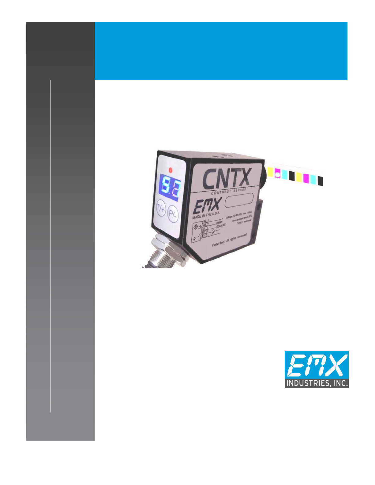
CNTX
C o n t r a s t S e n s o r


CNTX Operating Instructions 2
Document no. 10140104
Cautions and Warnings
SET-UP DISTANCE ADJUSTMENT:
As a general rule, the sensor should be fixed at a 15° to 20° angle from directly perpendicular to the
target surface. This will prevent direct reflected signal from glossy surfaces.
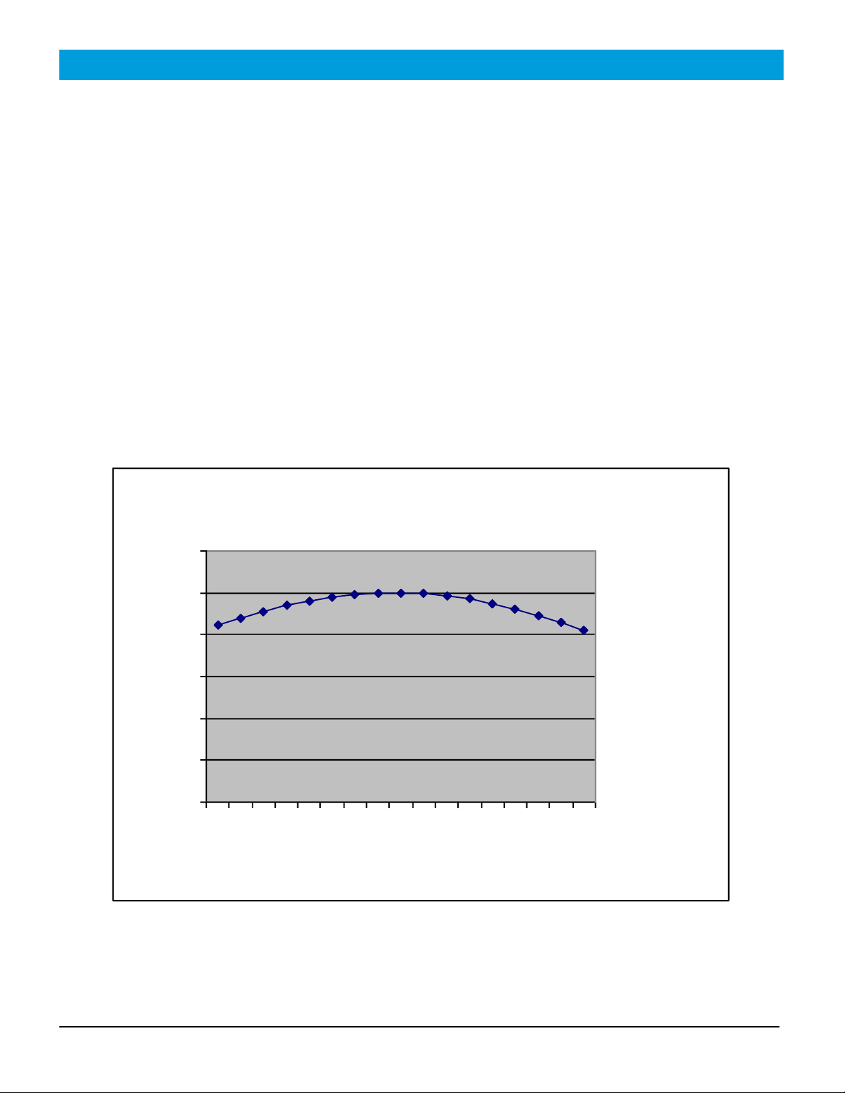
To obtain maximum tolerance to distance variation, place the target at the greatest distance it is likely
to be in the application, for example, flat against a guide surface. Carefully adjust the sensor distance
to obtain the highest reading on the white background and note the reading. Now move it slightly
further away, to get approximately 5% lower reading and fix sensor at that distance. This will allow the
target to move closer, back to the highest reading, then closer still down to 5% lower. The result
should be a minimum of 2mm of allowable flutter with <5% change in reading.
CAUTION: The discrete output must not be connected to outputs from other sensors (i.e. outputs
from multiple sensors must not be connected in parallel). Parallel connections may
damage sensor output circuitry.
CAUTION: Sensor is not suitable for wash down or hazardous environments; a separate enclosure
with the appropriate ratings is recommended for these applications"
IMPORTANT:
This product is an accessory or part of a system. Always read and follow the manufacturer’s
instructions for the equipment before connecting this product. Comply with all applicable codes and
safety regulations. Failure to do so may result in damage, injury or death.
Certifications (CE, CSA, ETL)
ETL, CE, and CSA certifications are in process.
CNTX Operating Instructions 3
Document no. 10140104
Product Overview
The CNTX sensor combines small spot size and fast response to achieve high-speed contrast detection
capable of detecting a wide variety of marks and objects. The CNTX effectively detects contrast
differences between many colors on various surfaces over a range of 50 grayscale levels. The
modulated white light source in the CNTX is focused to a 2.5 to 3mm spot and directed toward a
target. The diffused light returning to the sensor is measured. When the level is equal to or exceeds
the threshold the discrete output changes state. Due to the fast response of the sensor, it is suitable
for use in high-speed applications. The sensor provides a discrete output that automatically
configures to NPN and PNP. A PLC or a computer can be used to monitor the status of the discrete
output signal.
The CNTX is a reliable, compact sensor with high-speed sensing capabilities. Two seven segment
displays provide visual representation of the relative intensity from 00 to 50. The gain feature and 3
LED intensity settings provide for flexible operation over a wide range of colors.
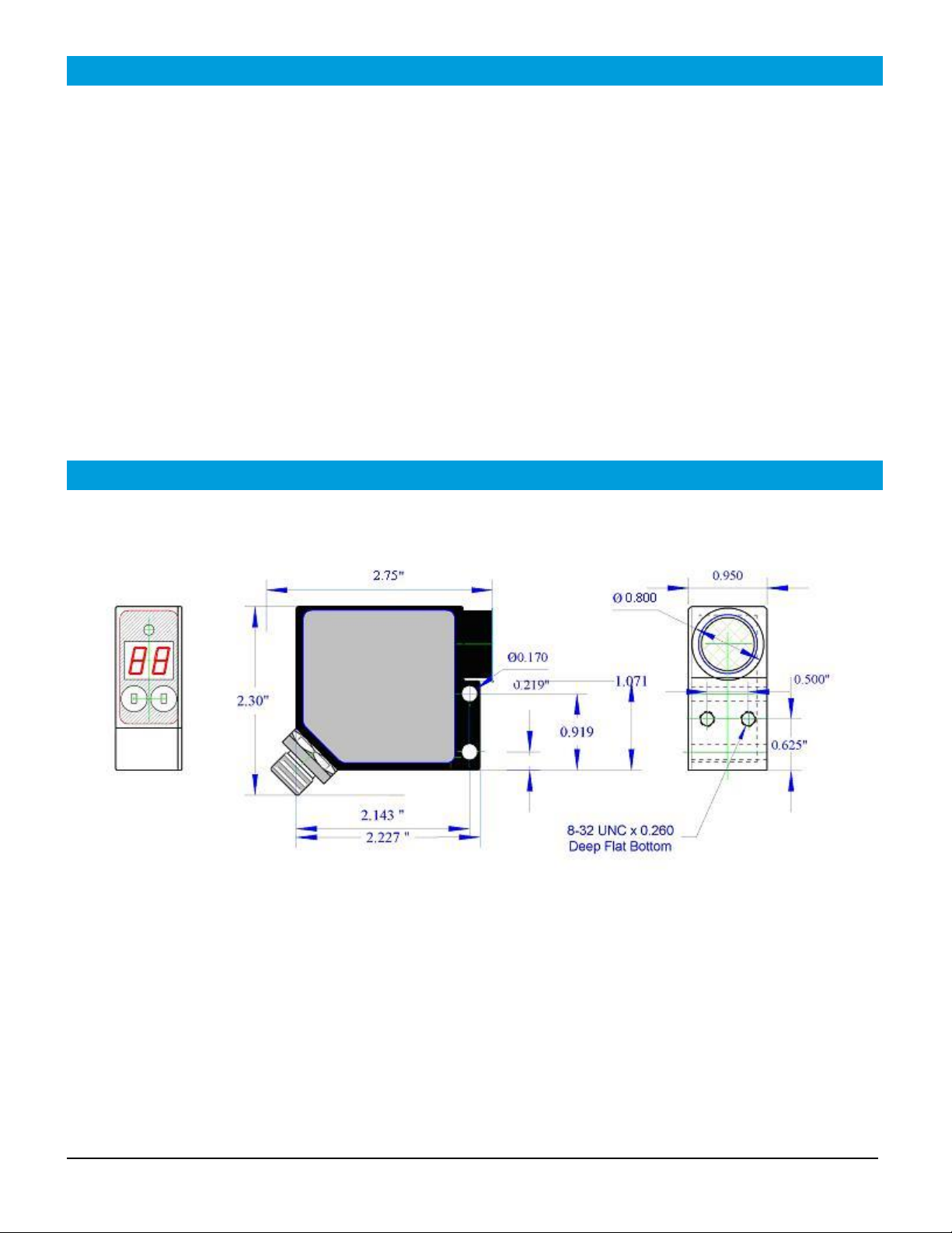
Dimensional Details

CNTX Operating Instructions 4
Document no. 10140104
Specifications
Specifications
White light source
Broad spectrum LED. Min. 100.000 hours
Sensing distance
26mm
Spot size (dia.)
0.5 or 3mm
Depth of field
+/- 3mm from focal point (approx 28mm)
Response time
25uS
Switching Frequency
40kHz
LED Intensity
3 Levels
Relative Intensity Display Range
00 to 50
Sensitivity
X1,X10
Signal Level
Two 7 Segment digits
Detection threshold
Two 7 Segment digits
Digital Output
Auto-Detect PNP / NPN
Output Function
NO/NC Selectable
Analog Output
0…5V (% of full-scale, 20mV resolution)
Security
LOCK/ UN-LOCK keypad
Power indicator
Green LED
Detect indicator
Red LED
Programming indicator
Yellow LED
Data retention
EEPROM non-volatile memory
Dimensions
2.0”(51mm) x 2.4”(61mm) x 0.9”(23mm)
Weight
0.21 lbs. (95 g)
Supply Voltage
10…24 VDC
Operating Current
60mA
Short Circuit Protection
Yes (Outputs)
Overload/Reverse Polarity
Protection
Yes(Supply Voltage)
Operating temperature
-20ºC…55ºC
Storage temperature
-20ºC…70ºC
Housing
Metal alloy
Mechanical protection
IP65 NOT FOR PRESSURE WASHDOWN

CNTX Operating Instructions 5
Document no. 10140104
Operation
QUICKSTART GUIDE
1. The display range is 00 through 50. The decimal points indicate the LED intensity level. The
RED LED above the display indicates that the intensity level exceeds the threshold setting.
2. Connect cable to power supply observing correct polarity. Reference wiring diagram.
3. Apply power; sensor will initialize and perform its power up sequence.
4. To obtain maximum tolerance to distance variation, place the target at the greatest distance it
is likely to be in the application, for example, flat against a guide surface. Select the target area
for the presence or non-presence, depending on which condition yields the higher signal level.
Carefully adjust the sensor distance to obtain the highest reading in this pre-determined area
and note the reading. Now move the sensor slightly further away, to get approximately 5%
lower reading and fix sensor at that distance. This will allow the target to move closer, back to
the highest reading, then closer still down to 5% lower. The result should be a minimum of
2mm of allowable flutter with <5% change in reading.
5. Place a sample (or use the back cover of this manual) with background into the sensor spot and
note the reading, move the sample 2nd area or condition that the sensor will encounter and
note the reading. Set the threshold between these 2 values.
6. Various adjustments may be made to increase or decrease sensitivity; refer to the Sections
Calibration Adjustment and LED Intensity Level. Refer to Section: Threshold, to alter threshold
setting.
7. User programmable parameters are discussed in detail in the following sections.
OPERATION
Power up
Upon power up, the sensor initializes by turning on all segments on the display and sequencing
through red, yellow and green on the status LED located above the display.
Intensity display mode
During normal operation the sensor display will indicate the relative intensity of a target within
the viewing area. The range of the relative intensity display is 00 through 50. The decimal
points on the display indicate the LED output intensity. No decimal points indicate low, one
decimal point indicates medium and two decimal points indicate high intensity.

CNTX Operating Instructions 6
Document no. 10140104
Operation (Continued)
Threshold
When the relative intensity level exceeds the threshold setting the red status LED will turn on
and the discrete output will activate, indicating detection of the target. When the relative
intensity level drops below the threshold (as determined by the hysteresis setting), the red LED
will extinguish and the discrete output will de-activate. The threshold setting allows the user to
select the detection level. The default setting is 15.
While the current threshold is shown on the display, press the + or –key to increase or
decrease the setting, then wait several seconds for the sensor to return to the normal intensity
display mode.
Local Lock
The local lock feature allows the sensor to be locked out, preventing adjustments by
unauthorized personnel. To lock the sensor, press the P/-and T/+ buttons for 3 seconds until
LL is displayed. To un-lock the sensor, press the T/+ and P/-for 3 seconds until LL is not
displayed. While the sensor is locked, pressing either P/-or T/+ will result in LL (Local Lock)
indication on the display.
Programmable Parameters
All adjustments made to these parameters are stored in memory and are retained when power is
removed. To enter programming mode press and hold the P/-key for several seconds, the LED
intensity setting will be displayed. Press and release the P/- key to scroll through the various settings.
Press and release the T/+ key to change a particular setting. Press and hold the P/-for several
seconds to return to the normal intensity display mode. The user programmable items are described
below.
LED Intensity Level (U)
The LED intensity is indicated on the display as U1, U2 and U3 for low, medium and high
intensity. Press and release the T/+ key to toggle through the 3 intensity levels. The default
setting is U2, medium intensity.
Hysteresis Level (H)
The hysteresis setting is indicated by H0 through H9. The hysteresis level is how far below the
threshold the signal must fall to de-activate or un-detect. The hysteresis can be set from 0 to 9.
For example, if the threshold is set at 25 and the intensity exceeds 25, the sensor will detect
and activate its output. With the hysteresis set to 5, the signal must drop to 20 to un-detect.
This feature is useful in cases where there may be variation within a target that might cause the
intensity to drop below the threshold slightly; the hysteresis allows the output to remain
activated until the level drops significantly. Press and release the T/+ key to change the
hysteresis setting. The default setting is 2.

CNTX Operating Instructions 7
Document no. 10140104
Operation (Continued)
Discrete Output Configuration
This setting allows the user to select either normal open (no) or normally closed (nc)
configuration. The normally open configuration de-activates the output during normal un-
detect operation, and activates the output upon detect. The normally closed configuration
activates the output during normal un-detect operation, and de-activates the output upon
detect. Press and release the T/+ key to toggle through the selections. Default is normally
open.
Extend Output Pulse (P)
This feature allows extending the minimum length of time that the discrete output remains
active following target detection. The sensor response can be in the 100uS (microsecond)
range, i.e. a target can move through the sensing range in 100uS and the discrete output would
active for only that duration. A slower acquisition system (PLC) may not sample its inputs at a
fast enough rate to capture the signal. The discrete output pulse can be extended from 0 to
90mS (milliseconds) in 10 mS increments as indicated by P0 though P9 on the display. Press
and release the T/+ key to toggle through the selections.
Null Offset (nu)
NOTE: Always perform the null function when installing or removing optional lens or
changing LED intensities.
The null feature allows the sensor to be “zeroed”. For example, when the target is not in view
and there is a background that causes a reading above zero, the null feature allows this level to
be subtracted out, allowing the display to indicate 00. Press and hold the T/+ key to null the
sensor. The display will flash the value that is being subtracted. To set the sensor back to a
true zero, aim the sensor away from any target and repeat the null process.
Gain Adjustment (r)
To change the gain setting press and release the T/+ key to toggle through the selections. R1
indicates a gain of 1; R2 indicates a gain of 10. The selected gain is stored in memory and is
retained when power is removed. After changing the gain setting always perform the null
offset (nu) to re-zero the sensor.

CNTX Operating Instructions 8
Document no. 10140104
Operation (Continued)
Teach Function
The teach function allows the user to set the threshold by placing a representative target
located at the required distance and allowing the sensor to determine the optimum LED
intensity and setting of the threshold level.
1. Press and hold the T/+ key for several seconds until the yellow led flashes.
2. Place the target at the appropriate distance from the sensor and press the P/- key. The
display will flash 3 times and the sensor will adjust the LED intensity level to achieve
reasonable signal level. The green LED will flash.
3. Remove the target and press the P/- key. The display will flash 3 times.
4. Exit the teach function and return to the normal operating mode by Pressing the T/+ key
for several seconds.
When in the teach mode the LED flashes constantly, yellow, green or red. Yellow indicates that
the sensor is ready to be taught the Detect level. Green indicates that the sensor is ready to be
taught the Undetect level. Red indicates that the last attempt to teach resulted in an error. If
the error occurred during the teaching of the Detect level then the signal intensity was less than
01. If the error occurred during the teaching of the Undetect level, then the signal intensity was
greater than or equal to the threshold level. In either case, repeat the teach function to
properly set the levels.
Output Signals
Discrete Output
The discrete output is a PNP/NPN configuration allowing the user to provide a load on this
output that is either pulled high to VDC or low to ground. The sensor monitors this level and
automatically determines whether to operate the PNP/NPN driver. This output is typically
connected to a PLC. The output remains active as long as the intensity level exceeds the
threshold, in high-speed applications it may be useful to use the Extend Output Pulse feature to
lengthen the signal duration to meet acquisition requirements of the PLC.
CAUTION: The discrete output must not be connected to outputs from other sensors (i.e.
outputs from multiple sensors must not be connected in parallel). Parallel
connections may damage sensor output circuitry.
CNTX Operating Instructions 9
Document no. 10140104
Operation (Continued)
Analog Output
The analog output is 0-5V with 20mV resolution (8-bit). Any standard analog input channel
typically available on a PLC may monitor this output. The analog output signal is useful in
applications where simply triggering on the threshold is insufficient. For example, constant
real-time monitoring of intensity in process allows minor fluctuations or trends to be detected
permitting corrective action to be taken.
Remote Lock/Unlock Input
The remote lock feature allows the user to lock out the local controls (keys) to prevent
operators from making unauthorized adjustments. This signal line must be connected to VDC
to lock the sensor. This line may be left unconnected if the lock feature is not used. While the
sensor is locked, pressing either P/-or T/+ will result in rL (remote Lock) indication on the
display.
CNTX sensor-to-target distance variation
0.00
0.20
0.40
0.60
0.80
1.00
1.20
-4.0
-3.0
-2.0
-1.0
0.0
1.0
2.0
3.0
4.0
Off-focus distance (mm)
Relative response (normalized)

CNTX Operating Instructions 10
Document no. 10140104
P/-
T/+
Controls and Indicators
Indicators
Green LED
Threshold Mode while in Undetect
Red LED
Detect
Yellow LED
Threshold Mode while in Detect
Display decimal points
None illuminated
LED low intensity
One illuminated
LED medium intensity
Two illuminated
LED high intensity
CNTX Operating Instructions 11
Document no. 10140104
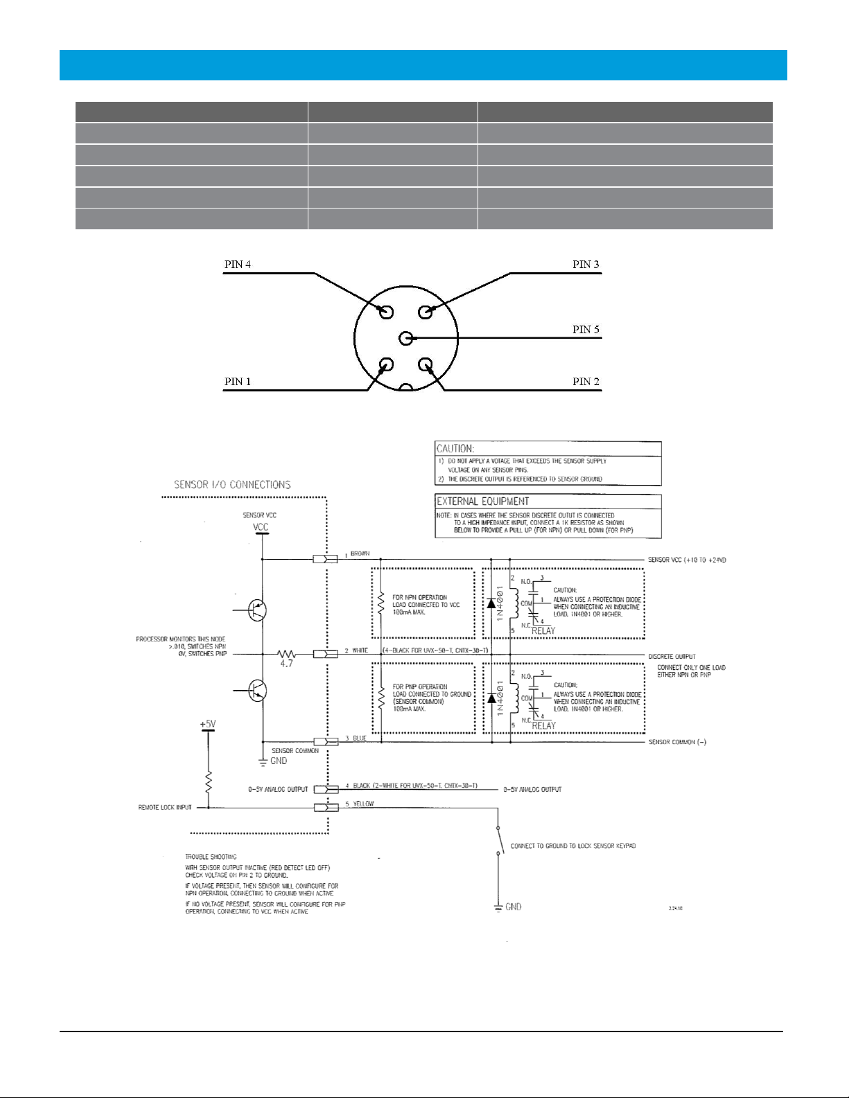
Connections
M12 Connector
Wire Color
Description
Pin 1
Brown
Power 10 to 24VDC
Pin 2
White
Discrete output, PNP/NPN, NO/NC
Pin 3
Blue
Ground
Pin 4
Black
Analog (0-5V)
Pin 5
Yellow
Remote lock
CNTX Operating Instructions 12
Document no. 10140104
Ordering Information
CNTX-30-0 Contrast sensor, 3mm spot size
CNTX-05-0 Contrast sensor, 0.5mm spot size
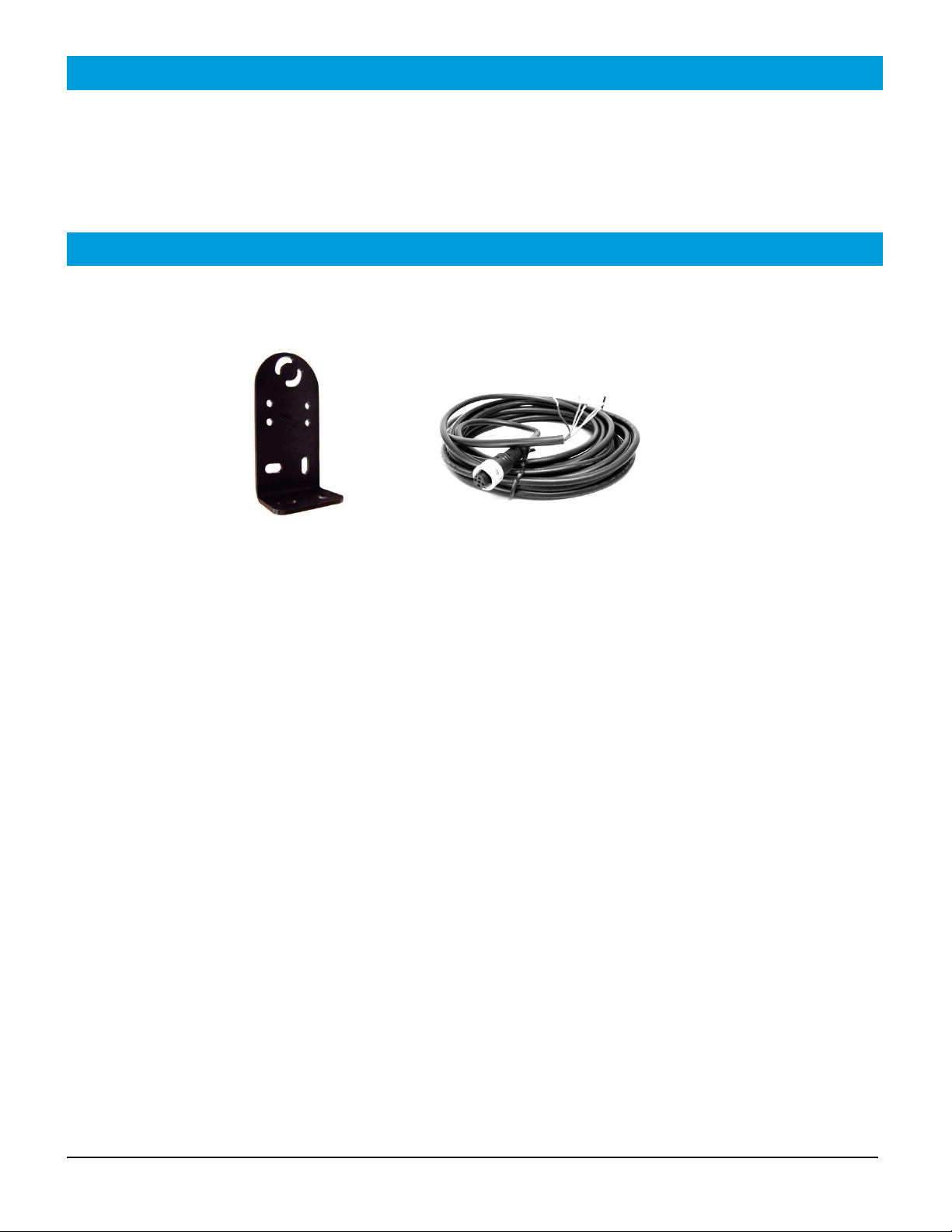
Accessories
UVX300-BRKT UVX 300-C
Bracket 5 meter cable with M12
5-pin connector

CNTX Operating Instructions 13
Document no. 10140104
Warranty
EMX Industries Incorporated warrants all products to be free of defects in
materials and workmanship for a period of two years under normal use and
service from the date of sale to our customer. This warranty does not cover
normal wear and tear, abuse, misuse, overloading, altered products, damage
caused by incorrect connections, lightning damage, or use other than intended
design.
There is no warranty of merchantability. There are no warranties expressed or
implied or any affirmation of fact or representation except as set forth herein.
EMX Industries Inc. sole responsibility and liability, and the purchaser’s
exclusive remedy shall be limited to the repair or replacement at EMX
Industries option of a part or parts found not conforming to the warranty. In
no event shall EMX Industries Inc. be liable for damages, including but not
limited to damages resulting from non-conformity, defect in material or
workmanship.
Effective date: January 1st, 2002

This manual suits for next models
2
Table of contents
Other EMX Industries Accessories manuals

EMX Industries
EMX Industries RAVEN User manual

EMX Industries
EMX Industries UVX-300P User manual

EMX Industries
EMX Industries UVX-300G-C User manual

EMX Industries
EMX Industries UVX-100 User manual

EMX Industries
EMX Industries IRB-MON User manual

EMX Industries
EMX Industries OWL User manual

EMX Industries
EMX Industries BriteX 1000P User manual

EMX Industries
EMX Industries UVX-300 User manual

EMX Industries
EMX Industries UVX-600G-C User manual

EMX Industries
EMX Industries UVX-300G User manual


