EMX Industries UVX-300P User manual
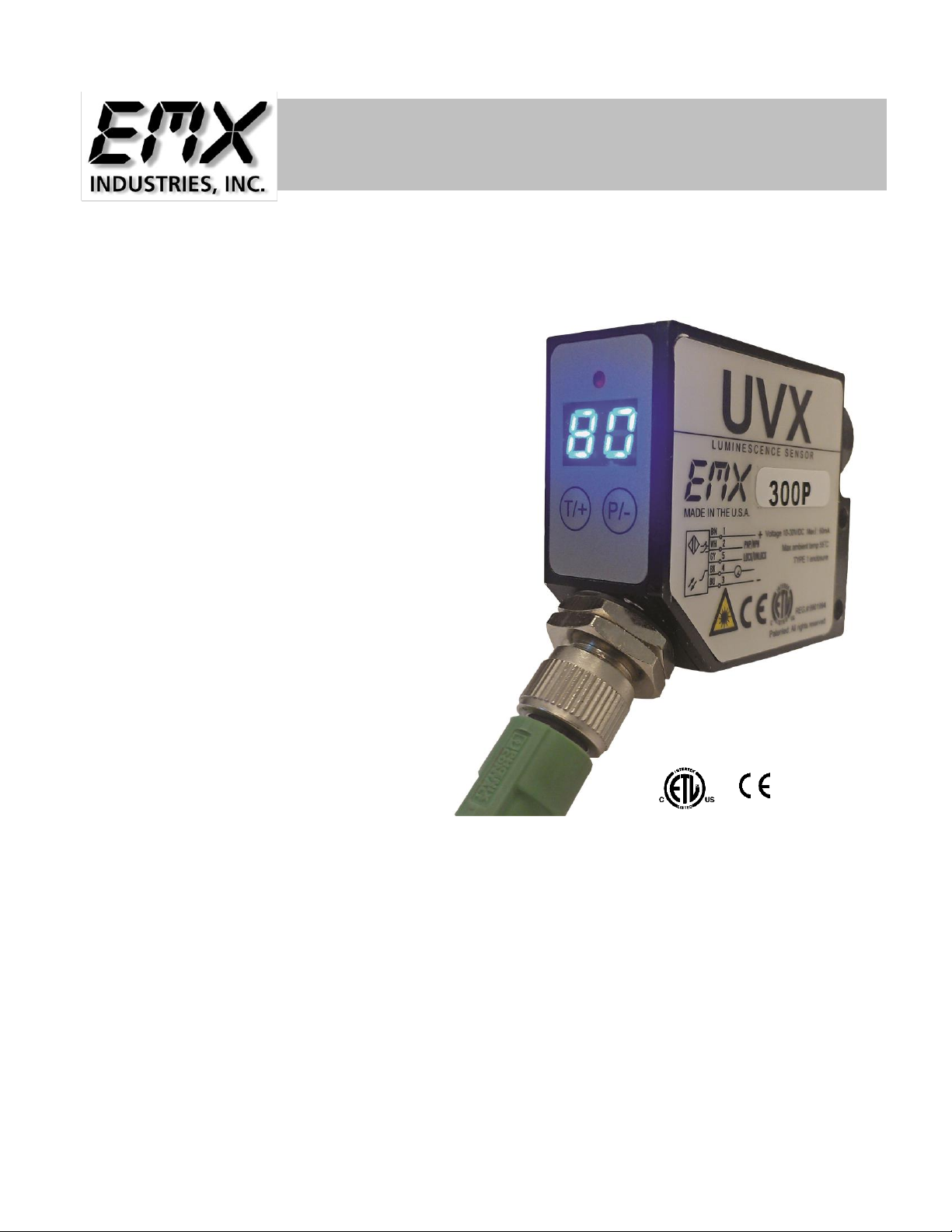
U
UV
VX
X-
-3
30
00
0P
P
INCLUDES UVX-300P-FG
P
Ph
ho
os
sp
ph
ho
or
re
es
sc
ce
en
nc
ce
e
s
se
en
ns
so
or
r
Operating Instructions
UVX-300P Operating Instructions 2
Document no. 10011004
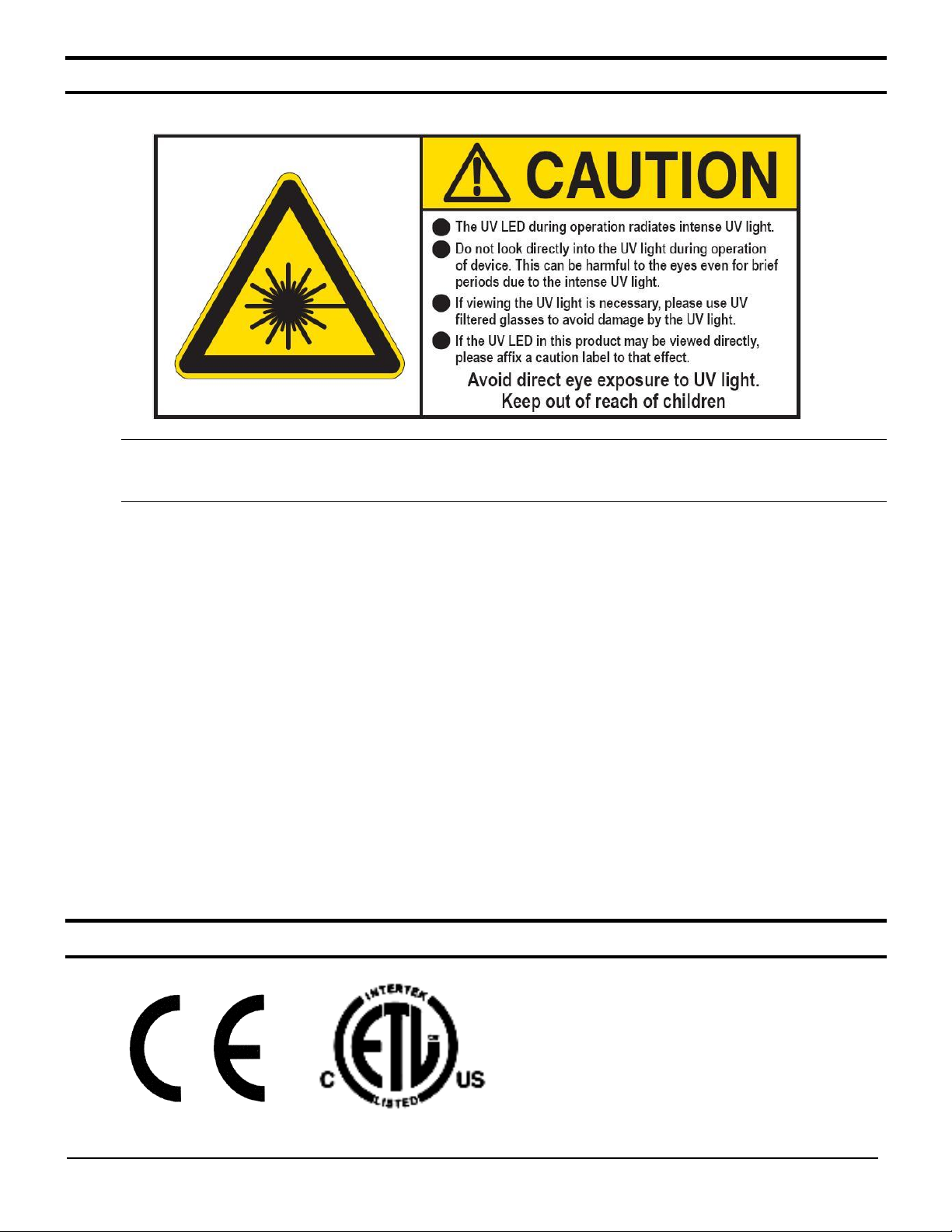
CAUTIONS AND WARNINGS
CAUTION: The discrete output must not be connected to outputs from other sensors (i.e. outputs
from multiple sensors must not be connected in parallel). Parallel connections may
damage sensor output circuitry.
IMPORTANT:
This product is an accessory or part of a system. Always read and follow the manufacturer’s
instructions for the equipment before connecting this product. Comply with all applicable codes and
safety regulations. Failure to do so may result in damage, injury or death.
Langue Française Attention:
•La LED UV rayonne la lumière UV intense lors du fonctionnement.
•N'examinez pas directement la lumière UV lors du fonctionnement de dispositif.
Ceci peut être nocif aux yeux, même pour la brève période due à la lumière UV intense.
•Si le visionnement de la lumière UV est nécessaire, employez svp les verres filtrés UV pour
éviter des dommages d'oeil par la lumière UV.
•Évitez l'exposition directe d'oeil à la lumière UV.
Subsistance hors de l'extension des enfants.
CERTIFICATIONS: CE, CSA, UL

UVX-300P Operating Instructions 3
Document no. 10011004
PRODUCT OVERVIEW
The UVX-300P sensor effectively detects phosphorescent materials and markers. Model UVX300P-FG is
specifically designed to detect phosphorescent materials while suppressing blue fluorescence from optical
brighteners commonly found in paper products. Refer to spectral response shown in the Specifications.
Since the sensor UV light source is not modulated, the sensor is sensitive to ambient light, therefore, a
shroud or low light conditions are necessary for reliable operation. The UV light source in the UVX300P is
directed toward a target and the visible light, resulting from the fluorescence of the material, is reflected
back to the sensor. When the reflected light level exceeds the threshold, the discrete output changes state.
Due to the fast response of the sensor, it is suitable for use in high-speed applications. The 50mm lens
accessory allows for very small spot size for fine resolution applications. The sensor provides both an
analog and a discrete output. The analog output signal has a 0 to 5 V range with 20mV resolution. A PLC
or a computer can be used to process the analog output and monitor the status of the discrete output signal.
The UVX 300P is a reliable, compact sensor with long range sensing capabilities. Two seven segment
displays provide visual representation of the relative intensity from 00 to 99. Calibration feature and 3 LED
intensity settings provide for flexible operation over wide range of distances and materials.
Specifications
UV light source
370nm UV LED, min.100,000 hours
Light spot size
6…8mm dia. @50mm
Light source intensity
3 levels
Sensing distance
Up to 350mm
Receiver spectral response
350…1000nm
Receiver spectral response (FG model)
500…1000nm
Response time
<150uS
Switching Frequency
6 kHz
Relative Intensity Display Range
00 to 99
Sensitivity
Adjustable
Signal level
Two 7-segment digits
Detection threshold
Two 7-segment digits
Digital Output
Auto-Detect PNP / NPN
Output function
NO/NC selectable
Analog Output
0…5V (20mV resolution)
Power indicator
Green LED
Detect indicator
Red LED
Programming indicator
Yellow LED
Data retention
EEPROM non—volatile memory
Dimensions
51mm x 61mm x 25mm (2.0” x 2.4” x 1.0”)
Weight
95g (0.21 lbs.)
Supply voltage
10…24 VDC
Operating current
60 mA
Short circuit protection
Discrete outputs
Overload / reverse polarity protection
Supply voltage
Operating temperature
-20°C…55°C
Storage temperature
-20°C…70°C
Housing
Metal alloy
Mechanical protection
IP65 NOT FOR PRESURE WASHDOWN

UVX-300P Operating Instructions 4
Document no. 10011004
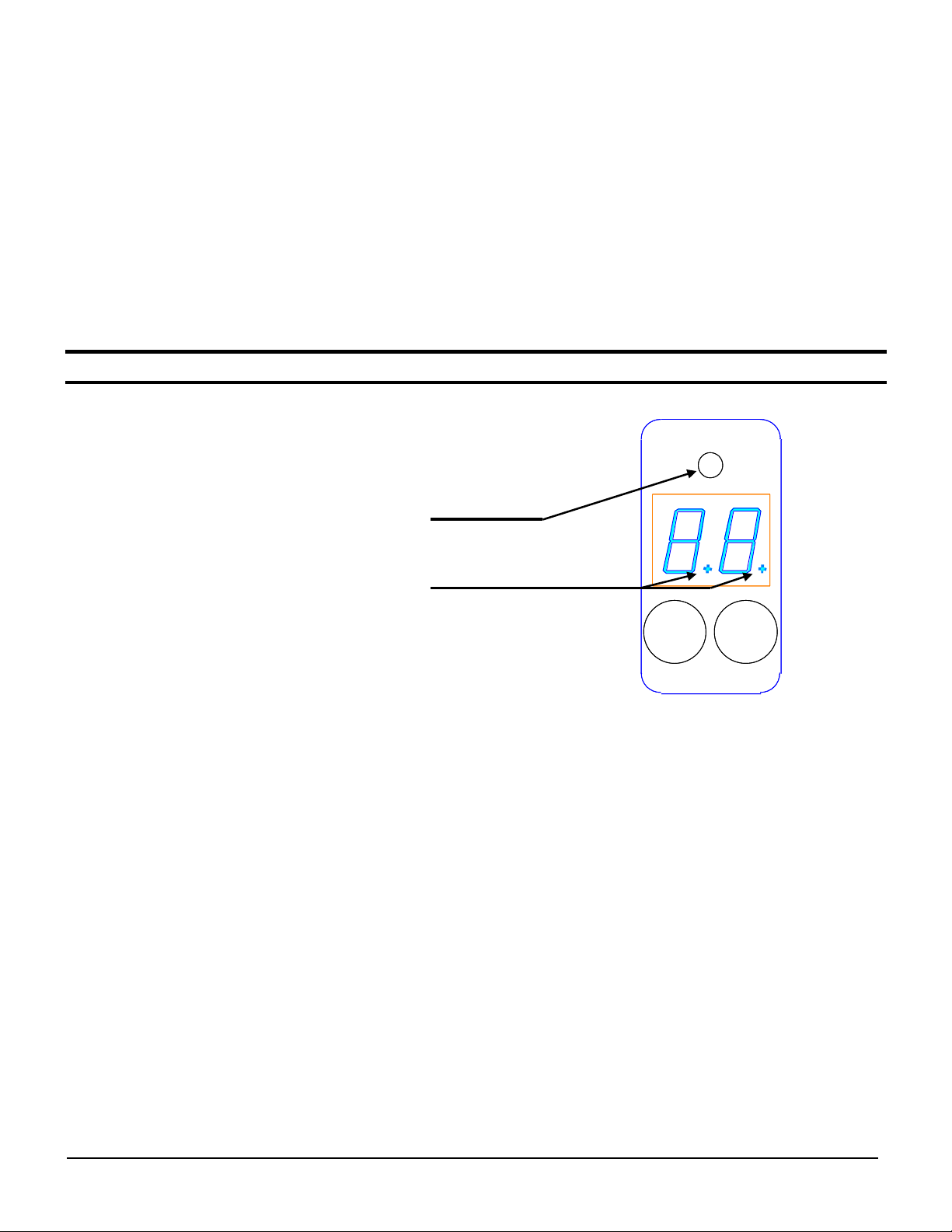
QUICKSTART GUIDE
1. The display range is 00 through 99. The decimal points indicate the LED intensity level. The RED
LED above the display indicates that the intensity level exceeds the threshold setting.
2. Connect cable to power supply observing correct polarity. Reference wiring diagram.
3. Apply power; sensor will initialize and perform its power up sequence.
4. The relative intensity will be displayed. By aiming the sensor away from any objects the display will
indicate 00. Aim the sensor at a target and the display will indicate an intensity measurement. Move
the paper further away from the sensor to decrease the intensity level.
5. Various adjustments may be made to increase or decrease sensitivity; refer to the Selections
Calibration Adjustment and LED Intensity Level. Refer to Section: Threshold, to after threshold
setting.
6. User programmable parameters are discussed in detail in the following sections.
OPERATION
Power up
Upon power up, the sensor initializes by turning on all segments on the display and sequencing
through red, yellow and green on the status LED located above the display.
Intensity display mode
During normal operation the sensor display will indicate the relative intensity of a target within its field
of view. The range of the relative intensity display is 00 through 99. The decimal points on the
display indicate the LED output intensity. No decimal points indicate low, one decimal point
indicates medium and two decimal points indicate high intensity.
Calibration Adjustment
The calibration feature allows the displayed measurement to be adjusted to the desired value by the
user.
Adjusting the measured value:
1. Place target in sensor’s field-of-view. The sensor will display the current reading.
2. Press either key (for less than 3 seconds); while the current reading is displayed the value
is flashed slowly indicating that the sensor is in the adjustment mode.
3. Press T/+ to increment the reading and P/- to decrement the reading.
4. Stop pressing either key and sensor returns to normal operating mode in 3 seconds.
Note:
•While adjusting the reading, when a limit is reached the display flashes at a faster rate.
•The selected gain is stored in memory and is retained when power is removed.
Local Lock
The local lock feature allows the sensor to be locked out, preventing adjustments by unauthorized
personnel. To lock the sensor, press the P/-and T/+ buttons for 3 seconds until LL is displayed. To
un-lock the sensor, press the T/+ and P/-for 3 seconds until LL is not displayed. While the sensor is
locked, pressing either P/-or T/+ will result in LL (Local Lock) indication on the display.

UVX-300P Operating Instructions 5
Document no. 10011004
Programmable Parameters
All adjustments made to these parameters are stored in memory and are retained when power is removed.
To enter programming mode press and hold the P/-key for several seconds, the current threshold setting
will be displayed. Press and release the P/- key to scroll through the various settings. Press and release
the T/+ key to change a particular setting. Press and hold the P/-for several seconds to return to the normal
intensity display mode. The user programmable items are described below.
Threshold
When the relative intensity level exceeds the threshold setting the red status LED will turn on and the
discrete output will activate, indicating detection of the target. When the relative intensity level drops
below the threshold (as determined by the hysteresis setting), the red LED will extinguish and the
discrete output will de-activate. The threshold setting allows the user to select the detection level.
The default setting is 15.
To adjust the threshold, enter programming mode, press and hold the P/-key for several seconds,
the current threshold setting will be displayed. Press and release the T/+ key to increase the
threshold level, to decrease the threshold level, continue to hold the T/+ key until the value
approaches 99 then wraps around to 00.
LED Intensity Level (U)
The LED intensity is indicated on the display as U1, U2 and U3 for low, medium and high intensity.
Press and release the T/+ key to toggle through the 3 intensity levels. The default setting is U2,
medium intensity.
Hysteresis Level (H)
The hysteresis setting is indicated by H0 through H9. The hysteresis level is how far below the
threshold the signal must fall to de-activate or un-detect. The hysteresis can be set from 0 to 9. For
example, if the threshold is set at 25 and the intensity exceeds 25, the sensor will detect and activate
its output. With the hysteresis set to 5, the signal must drop to 20 to un-detect. This feature is useful
in cases where there may be variation within a target that might cause the intensity to drop below the
threshold slightly; the hysteresis allows the output to remain activated until the level drops
significantly. Press and release the T/+ key to change the hysteresis setting. The default setting is
2.
Discrete Output Configuration
This setting allows the user to select either normal open (no) or normally closed (nc) configuration.
The normally open configuration de-activates the output during normal un-detect operation, and
activates the output upon detect. The normally closed configuration activates the output during
normal un-detect operation, and de-activates the output upon detect. Press and release the T/+ key
to toggle through the selections. Default is normally open.
Extend Output Pulse (P)
This feature allows extending the minimum length of time that the discrete output remains active
following target detection. The sensor response can be in the 100uS (microsecond) range, i.e. a
target can move through the sensing range in 100uS and the discrete output would active for only
that duration. A slower acquisition system (PLC) may not sample its inputs at a fast enough rate to
capture the signal. The discrete output pulse can be extended from 0 to 90mS (milliseconds) in 10
mS increments as indicated by P0 though P9 on the display. Press and release the T/+ key to toggle
through the selections.

UVX-300P Operating Instructions 6
Document no. 10011004
Null Offset (nu)
NOTE: Always perform the null function when installing or removing optional lens or changing LED
intensities.
The null feature allows the sensor to be “zeroed”. For example, when the target is not in view and
there is a background that causes a reading above zero, the null feature allows this level to be
subtracted out, allowing the display to indicate 00. Press and hold the T/+ key to null the sensor.
The display will flash the value that is being subtracted. To set the sensor back to a true zero, aim
the sensor away from any target and repeat the null process.
Teach Function
The teach function allows the user to set the threshold by placing a representative target located at
the required distance and allowing the sensor to determine the optimum LED intensity and setting of
the threshold level.
1. Press and hold the T/+ key for several seconds until the yellow led flashes.
2. Place the target at the appropriate distance from the sensor and press the P/- key. The
display will flash 3 times and the sensor will adjust the LED intensity level to achieve
reasonable signal level. The green LED will flash.
3. Remove the target and press the P/- key. The display will flash 3 times.
4. Exit the teach function and return to the normal operating mode by Pressing the T/+ key for
several seconds.
When in the teach mode the LED flashes constantly, yellow, green or red. Yellow indicates that the
sensor is ready to be taught the Detect level. Green indicates that the sensor is ready to be taught
the Undetect level. Red indicates that the last attempt to teach resulted in an error. If the error
occurred during the teaching of the Detect level then the signal intensity was less than 01. If the
error occurred during the teaching of the Undetect level, then the signal intensity was greater than or
equal to the threshold level. In either case, repeat the teach function to properly set the levels.
Output Signals
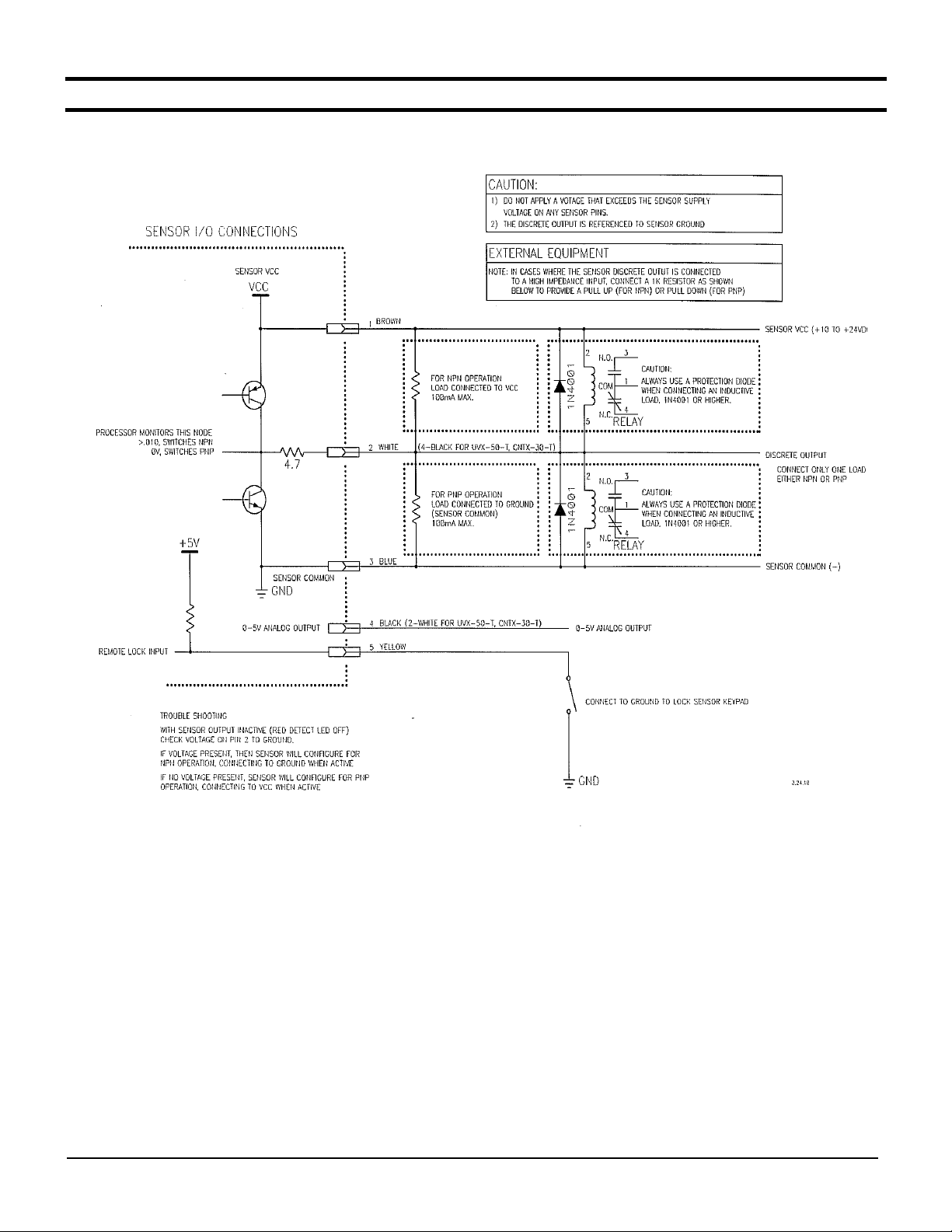
Discrete Output
The discrete output is a PNP/NPN configuration allowing the user to provide a load on this output
that is either pulled high to VDC or low to ground. The sensor monitors this level and automatically
determines whether to operate the PNP/NPN driver. This output is typically connected to a PLC.
The output remains active as long as the intensity level exceeds the threshold, in high-speed
applications it may be useful to use the Extend Output Pulse feature to lengthen the signal duration
to meet acquisition requirements of the PLC.
CAUTION: The discrete output must not be connected to outputs from other sensors (i.e. outputs
from multiple sensors must not be connected in parallel). Parallel connections may
damage sensor output circuitry.
UVX-300P Operating Instructions 7
Document no. 10011004
P/-
T/+
Analog Output
The analog output is 0-5V with 20mV resolution (8-bit). Any standard analog input channel typically
available on a PLC may monitor this output. The analog output signal is useful in applications where
simply triggering on the threshold is insufficient. For example, constant real-time monitoring of
intensity in process allows minor fluctuations or trends to be detected permitting corrective action to
be taken.
Remote Lock/Unlock Input
The remote lock feature allows the user to lock out the local controls (keys) to prevent operators from
making unauthorized adjustments. This signal line must be connected to VDC to lock the sensor.
This line may be left unconnected if the lock feature is not used. While the sensor is locked,
pressing either P/-or T/+ will result in rL (remote Lock) indication on the display.
Display Indicators
Indicators
•Green LED Threshold Mode while in Undetect
•Red LED Detect
•Yellow LED Threshold Mode while in Detect
Display decimal points
•None illuminated LED low intensity
•One illuminated LED medium intensity
•Two illuminated LED high intensity
UVX-300P Operating Instructions 8
Document no. 10011004
M12 connector pin assignments
M12 Connector
Wire Color
Description
Pin 1
Brown
Power 10 to 24VDC
Pin 2
White
Discrete output, PNP/NPN, NO/NC
Pin 3
Blue
Ground
Pin 4
Black
Analog output 0 to 5V DC
Pin 5
Yellow
Remote Lock (connect to sensor V+)
Ordering information
UVX300P Phosphorescence sensor
UVX300P-FG Phosphorescence sensor, for use with yellow/green/ red pigment
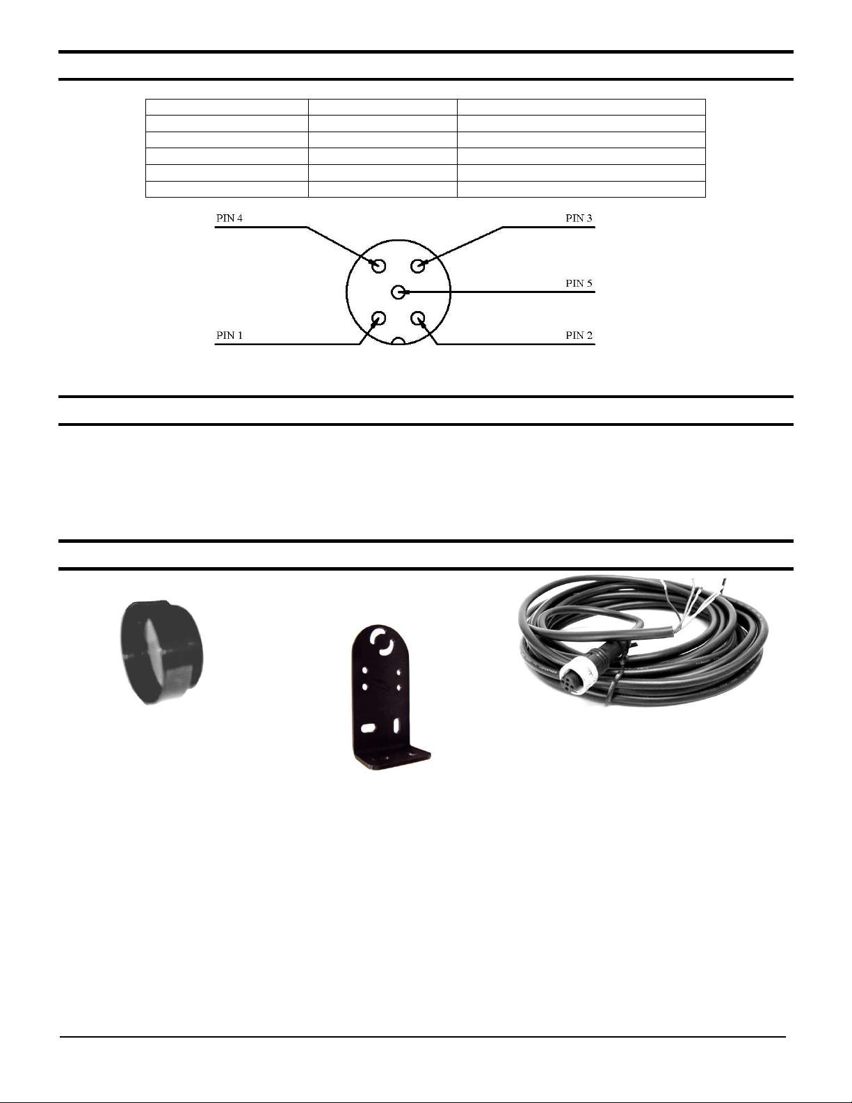
Accessories
UVX 300-L50 UVX300-BRKT UVX 300-C
50mm focal lens Bracket 5 meter cable with M12
5-pin connector

UVX-300P Operating Instructions 9
Document no. 10011004
Mounting UVX-300-L50 Focal lens
The focal lens is mounted by screwing the collar into the sensors standard lens collar. An anti—
vibration material is present on the focal lens threads. If necessary, use soft cloth with pliers to
remove.
Dimensional Details
UVX-300P Operating Instructions 10
Document no. 10011004
Sensor I/O Connections
UVX-300P Operating Instructions 11
Document no. 10011004
Warranty
UVX-300P Operating Instructions 12
Document no. 10011004
4564 Johnston Parkway
Cleveland, Ohio 44128
United States of America
WEB http://www.emxinc.com
Technical Support: (216) 834-0761
E-mail: [email protected]
Sales: (216) 518-9888
Fax (216) 518-9884
E-mail [email protected]
Demonstration target for UVX 300P
Revision 1.0
9.17.14
Table of contents
Other EMX Industries Accessories manuals

EMX Industries
EMX Industries UVX-600G-C User manual

EMX Industries
EMX Industries CNTX Series User manual

EMX Industries
EMX Industries RAVEN User manual

EMX Industries
EMX Industries UVX-100 User manual

EMX Industries
EMX Industries UVX-300G-C User manual

EMX Industries
EMX Industries UVX-300 User manual

EMX Industries
EMX Industries BriteX 1000P User manual

EMX Industries
EMX Industries ColorMax CM1000-1-4 User manual

EMX Industries
EMX Industries OWL User manual

EMX Industries
EMX Industries UVX-300G User manual


