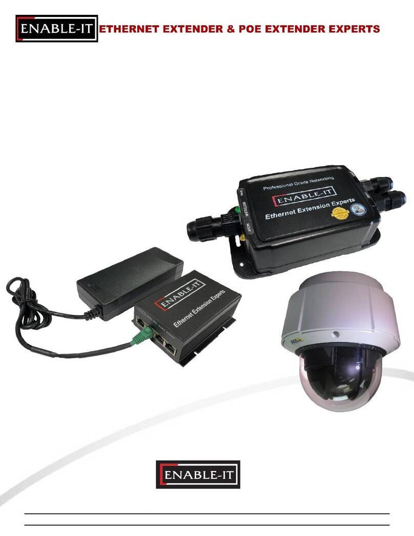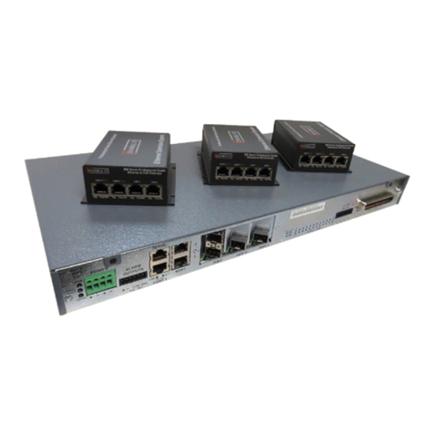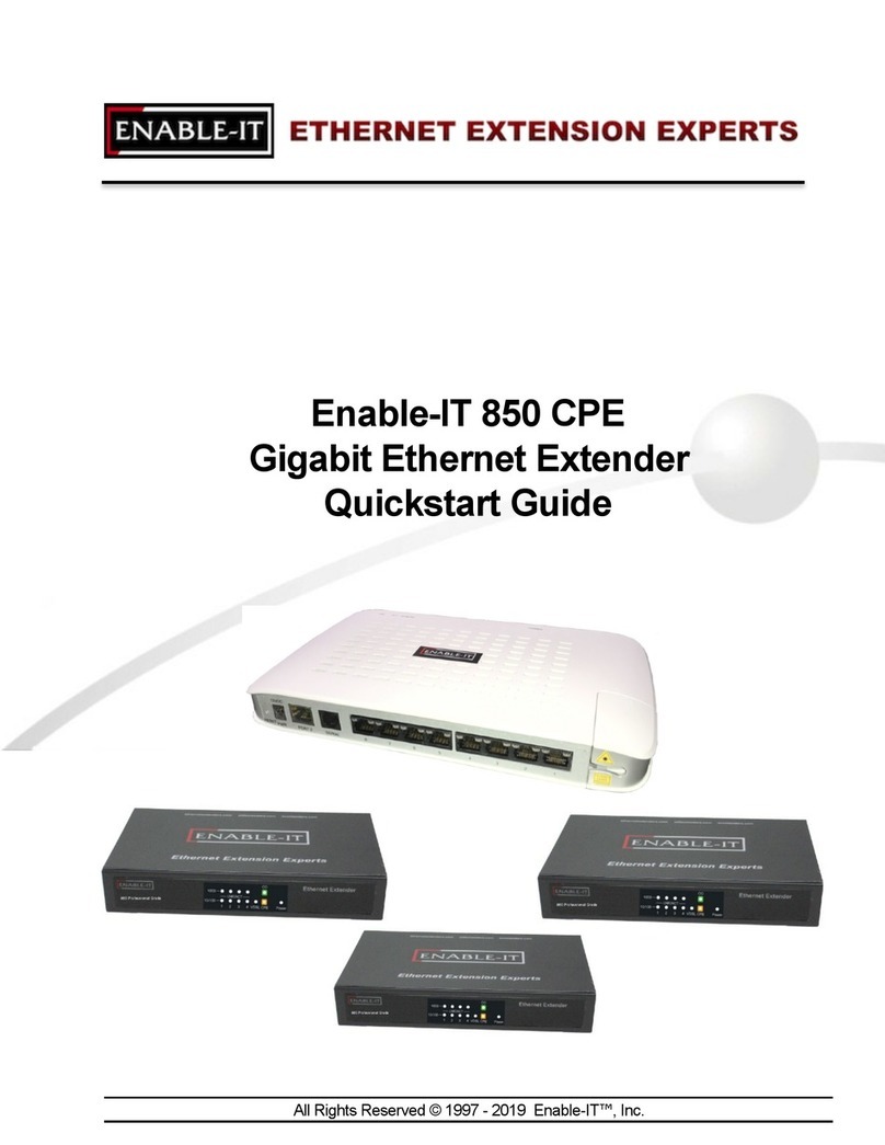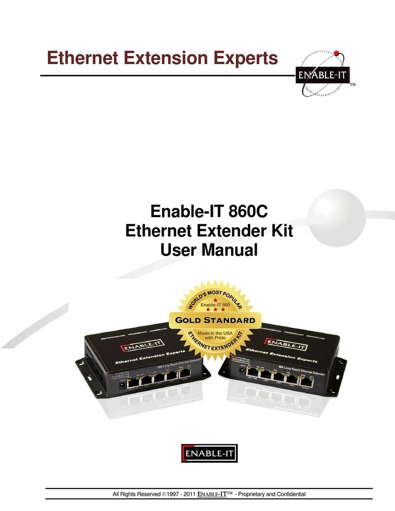
All Rights Reserved 1997 - 2014 Enable-IT, Inc. Page 4 of 6
Cabling Devices to the Enable-IT 850 Pro Extended Ethernet Kit
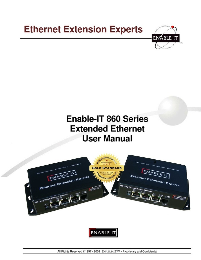
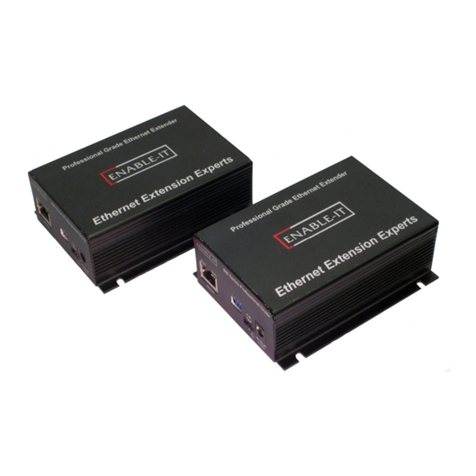
Attach your remote LAN device to the 850 Pro CPE unit LAN ports with Ethernet patch
cord provided. Attach your local LAN to the 8950 LAN ports with Ethernet patch cord
provided. Attach the power adapters to both 850 Pro units.
Attach your local Interlink cabling end to the 8950 unit Interlink port –Then do the same
for the remote end and plug into the 850 Pro CPE unit Interlink port. The Sync LED’s
will flicker in a sequence talking to each other until they go solid. Your equipment should
now be powered up and functioning.
LED indicators will provide visual operational status of the 850 Pro units.
Mode –Yellow Solid LED
Off = CO unit
On = CPE unit
Sync –Green slow to fast flicker LED on power up –indicates negotiation of a link
–Green solid LED indicates link established and rapid pulse is traffic
Act –Yellow LED
Off = No device attached or detected
On = Solid, indicates the presence of local LAN
On = Blinking, indicates the presence of local LAN traffic
Pwr –Green Solid LED indicates the unit is receiving 5v power
Troubleshooting
First examine the backbone wiring pair and make sure you have solid connections. The
Interlink Sync LED will be lit solid Green with rapid pulsing on each 850 Pro unit to show
proper connection and pairing. If the Interlink Sync LED Link is flashing slow to fast and
never goes solid…. Then follow the steps below:
1) Make sure your wiring is straight through and not connected to any Telco punch
down blocks; If so remove from the block and use Telco butt clips to bridge
wire.
2) Check for a firm connection of the RJ-45 connections in each 860 Pro unit, and
power is applied to the 850 Pro CO & CPE units.
3) You can easily isolate any issue by performing an Out Of the Box Test
(OOTBT). This test will confirm the correct working order of your Enable-IT 860
Pro Ethernet Extender Kit. This will point to a possible issue with your long
distance Interlink wiring being affected by possible outside interference.
Performance Settings (DIP Switch)
If you are experiencing performance issues with your Ethernet connection you may use the
following DIP switch settings to adjust your application. For DIP switch 2-4 you must toggle
both symmetrically, in other words the CO and CPE must match. If you turn DIP switch 3 Up
(Off) on the CO, then you must do so for the CPE and vice-versa.
Switch 1: CO / CPE Mode
CO Mode –Up / Off Position
CPE Mode –Down / On Position
Central Office Equipment (CO) is generally the equipment residing at the Carrier
Telephone office or the head end of a circuit. Customer Premise Equipment (CPE) is
generally the equipment residing on the customer side of a circuit. Typically you would
place the CO at the local end and the CPE at the remote end for reference only. CO’s
only communicate with CPE’s.
