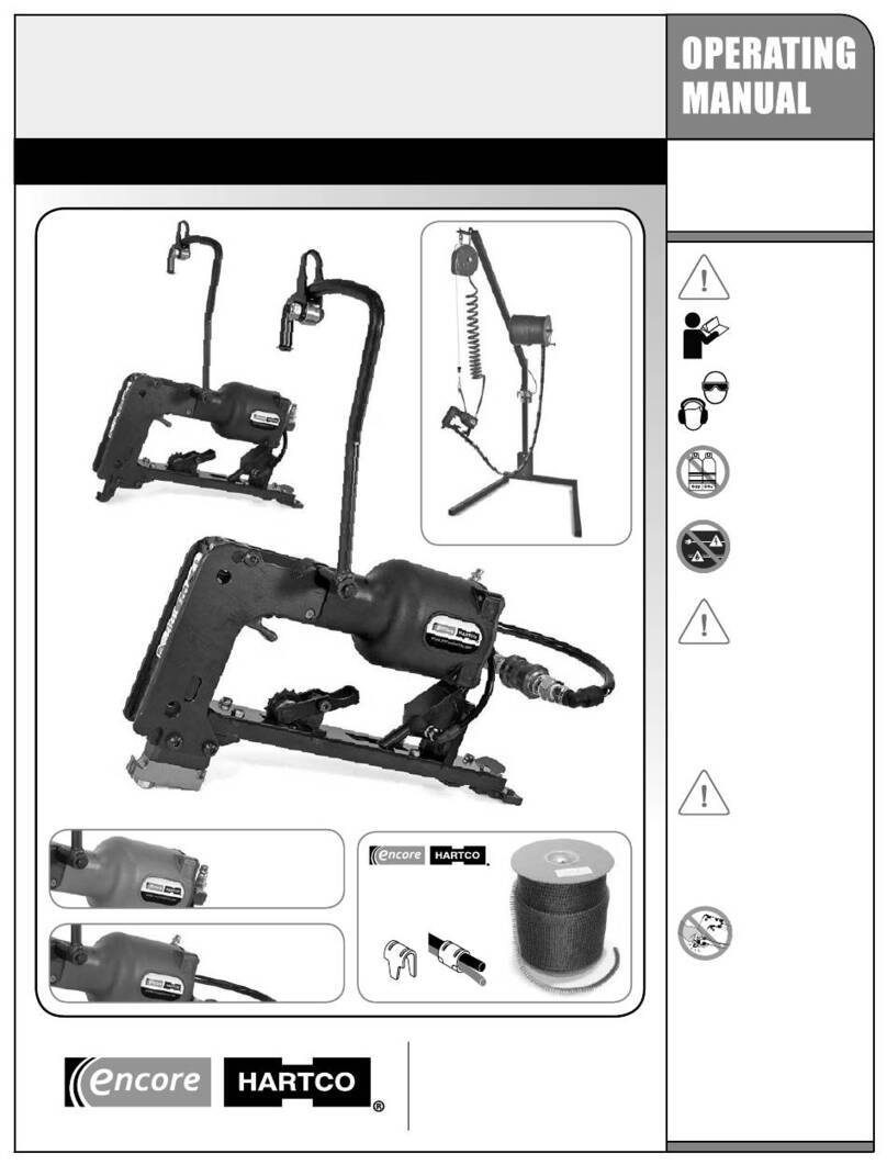
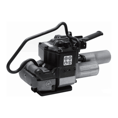
Encore Hartco Eclipser 2000 User manual

SAFETY
WARNING
READ THE ENTIRE MANUAL
BEFORE OPERATING THE TOOL.
SAFETY GLASSES (ANSI A87)
should always be worn by all in
the work area while operating,
maintaining or repairing a
tool.Wear personal protective
equipment as required.
NEVER use oxygen, carbon
dioxide or any other bottled gas
as a power source for this tool, as
it will explode and cause serious
injury.
BEFORE using tool, check work
area for hidden electric cables,
utility lines, gas pipes, etc. that
can cause a hazard if damaged
by the tool.
INSPECT TOOL BEFORE
EACH USE. Make sure bolts
and cap screws are tight and
trigger moves freely.
Never use a tool that leaks air, has missing parts,
is damaged, or needs repair.
Do not modify this tool without consulting with
an ENCORE HARTCO tool specialist rst.
Use only parts, fasteners and accessories
recommended and sold by ENCORE HARTCO and
its authorized distributors.
TO PREVENT SERIOUS
INJURY:
• Do not use the tool when you are tired or
under the inuence of drugs, alcohol or
medication.
• Remove all fasteners from tool BEFORE
connecting air.
KEEP HANDS AND FINGERS
AWAY FROM BLADE AND ANVIL
AREA when connecting air
supply and operating tool.
• DISCONNECTTHE AIR SUPPLY when
mechanically clearing a jam, performing
maintenance or repairs, and whenever the
tool is not in use.
• NEVER POINT THE TOOL TOWARD YOURSELF
OR ANYONE ELSE.
• ALWAYS KEEP YOUR FINGER OFFTHE
TRIGGER unless actually applying a clip.
Unintended pressure on trigger could cause
tool to eject a fastener.
with Hanger & Safety Guard options
www.encorehartco.com
Northbrook, IL 60062 U.S.A.
Phone: (224) 723-5524
Fax: (224) 723-5526
For best results, use genuine
• Encore Hartco E-Clips
• WA Fasteners Clinch Clips
Optional
Hanger
Assembly
30131
4C 2021-04-29
Eclipser
2000
Pneumatic Clinch Clip
Closure Tool
Optional
Lexan
Safety
Guard
30090
Optional
Steel
Safety
Guard
30094
MADE IN THE U.S.A.
Black Housing
HR2000 Series
Encore Hartco
STANDARD“T” MODEL
“T” (Thin) Models
for Trap & Cage
Assembly
Green Housing
EA2000 Series
Red Housing
SN2000 Series
It is the employer’s responsibility to assure
this manual is read and understood by all
personnel assigned to use this tool, and that
manual is kept on hand for future reference.

20012
NUT
20011
SCREW
20021
NUT
30040
PUSHER
SPRING
20038
SHCS
20012
NUT
30051
PUSHER “A”
20034
SCREW
30029
PUSHER
PULL
30000
MAIN VALVE
20003
O-RING
20000
O-RING
20001
O-RING
20019
PLUG
20035
PLUG (RED)
20011
SCREW
30001
HOUSING
CAP
15316
SCREW
55095
HANGER
YOKE
20037
E-CLIP
30130
HANGER
30033
HANGER
PIN
15037
BEARING
20012
NUT
20065
SCREW
20036
C-CLIP
20519
BHCS
30011
TRIGGER
3002230056
30021
PIN, BLADE
30004
PISTON
ASSEMBLY
30005
COMPRESSION
SPRING
30023
SHOULDER
SCREW
30041
PIN
20004
O-RING
20036
C-CLIP
30006
GROOVED
PIN
30010
TRIGGER
LEVER
30009
VALVE SLEEVE
20007
O-RING
30008
TRIGGER
VALVE
30007
SPRING
20005
O-RING
20006
O-RING
30017
YOKE
30018
ROLLER
30019
LINK
30020
PIN, ROLLER
20018
DOWEL PIN
20009
DOWEL
PIN
30015
PIN
30014
TOP PLATE
20010
PIN
30002
HOUSING (GREEN)
35002
HOUSING (RED)
38002
HOUSING (BLACK)
BLADE
SEE CHART
BLADE
GUIDE
SEE CHART
NEXT PAGE
SIDE PLATE - Right
SEE CHART
FRONT
PLATE
SEE CHART
NEXT PAGE
ANVIL
SEE CHART
PUSHER
w/Latch
SEE CHART
NEXT PAGE
MAGAZINE
SEE CHART ON
NEXT PAGE
Standard Models Thin “T” Models
20037
E-CLIP
Standard Thin “T”
20037
E-CLIP
SIDE PLATE - Left
SEE CHART
30016
SPRING
4C 2021-04-29
2
Eclipser 2000 – Drawing of Tool and Options
PROBLEM CAUSE SOLUTION
Blade does not Sticky Main Valve Lubricate Main Valve (#30000) and
check that Main Valve moves
return
Dirty Main Valve 1/32” hole must be clear
Loose Housing Cap Screw(s) Tighten all four Screws (#20011)
Clip jammed in tool Disconnect air supply, remove clip
Clip jamming Clips loaded backwards Reorient strip so that single ear of
into the Magazine clip is facing toward clipping area
PROBLEM CAUSE SOLUTION
Sluggish tool Dry Main Valve Lubricate Main Valve (#30000)
Tool not cycling Clogged Trigger Valve Clean Trigger Valve (#30008)
Clips not feeding Obstruction in Magazine Remove obstruction
Broken Pusher Spring Replace Pusher Spring (#30040)
Loose clips Low air pressure Increase pressure to 80 psi
Worn Blade or Anvil Replace worn part (Part #s on pg 3)
TROUBLESHOOTING
SAFETY GUARD - STEEL
30094
SAFETY GUARD - LEXAN
30090
CLOSED
OPEN
E-CLIPS/CLINCH CLIPS
Go to encorehartco.com to
nd the right clip size(s) for
your tool model
www.encorehartco.com
(224) 723-5524
HANGER ASSEMBLY
30131
SAFETY GUARD - STEEL
30094
20440
FHCS
20440
FHCS
30093
FRONT
PLATE
30093
FRONT
PLATE
30094.3
STEEL GUARD
WELDMENT
30097
LEXAN
GUARD
30092
BRACKET
15061
BHCS
SAFETY GUARD - LEXAN
30090

Blade Guide
Nut & Screw
Fits
(Orientation key
Pusher Front
or
Side Plate
Clip
Model # Anvil Blade
only on #30200)
w/Latch Plate Magazine
e-Clip & Pin
Right Left
Width
2000-1020 30210 30220 30202 30051 30022 38050 20012 & 30023 30012 30013 A
2000-1020S 30210 30220 30203 30051 30022 38050 20012 & 30023 30012 30013 A
2000-1022 30210 30222 30201 30051 30022 38050 20012 & 30023 30012 30013 A
2000-1024 30210 30224 30208 30051 30022 38050 20012 & 30023 30012 30013 A
2000-1121 30211 30221 30201 30051 30022 38050 20012 & 30023 30012 30013 A
2000-1234 30212 30234 30254 30049 30022 38050 20012 & 30023 30012 30013 A
2000-1533 30215 30233 30255 30051 30056 38050 20012 & 30023 30012 30013 A
2000-1926 30219 30226 30203 30051 30022 38050 20012 & 30023 30012 30013 A
2000-1929 30219 30229 30203 30051 30022 38050 20012 & 30023 30012 30013 A
2000-3236 30232 30236 30207 30031 30022 38024 20012 & 30023 30012 30013 E
2000-4050 30240 30250 30205 30030 30022 38024 20012 & 30023 30012 30013 F
2000-4139 30241 30239 30209 30031 30022 38024 20012 & 30023 30012 30013 E
2000-4151T 30241 30251
30205
30035 30022 38024 20037 & 30041
30012 30013
F
2000-4157T 30241 30257
30204
30035 30022 38060 20037 & 30041
30012 30013
F
2000-4528 30245 30228 30256 30051 30056 38050 20012 & 30023 30012 30013 A
2000-6075 30260 30275 30200 030025 30022 38024 20012 & 30023 30012 30013 F, H
2000-6080 30260 30280 30200 030025 30022 38024 20012 & 30023 30012 30013 F, H
2000-6082 30260 30282 30200 030025 30022 38024 20012 & 30023 30012 30013 F, H
2000-6181 30261 30281 30200 030025 30022 38024 20012 & 30023 30012 30013 F, H
2000-6181T 30261 30281
30200
0
30035 30022 38024 20037 & 30041
30012 30013
F, H
2000-6183 30261 30283 30200 130025 30022 38060 20012 & 30023 30012 30013 F, H
2000-6183T 30261 30283
30200
1
30035 30022 38060 20037 & 30041
30012 30013
F, H
2000-6185 30261 30285 30200 030025 30022 38024 20012 & 30023 30012 30013 F, H
2000-6187T 30261 30287
30200
1
30035 30022 38060 20037 & 30041
30012 30013
F, H
2000-6189 30261 30289 30200-X 130025 30022 38060 20012 & 30023 30012 30013 F, H
2000-6788 30267 30288 30206 30025 30022 38060 20012 & 30023 30012 30013 F, H
2000-6791T 30267 30291
30206
30035 30022 38060 20037 & 30041
30012 30013
F, H
2000-6794 30267 30294 30302 30025 30022 38061 20012 & 30023 30012 30013 F, H
2000-7174 30271 30274 30304 30039 30056 38062 20012 & 30023 30036 30037 H
2000-7195 30271 30295 30304 30039 30056 38062 20012 & 30023 30036 30037 H
2000-7196 30271 30296 30303 30039 30056 38062 20012 & 30023 30036 30037 H
2000-7197 30271 30297 30302 30039 30056 38061 20012 & 30023 30036 30037 H
20012
&
20023
20037 &30041
MODEL-SPECIFIC PARTS
3
4C 2021-04-29
XXXX X
00000
SERIAL
NUMBER
BLADE GUIDE
ORIENTATION
KEY VISIBLE
HERE
TOOL IDENTIFICATION
0 / 1
AA
ANVIL NUMBER
LOCATED ON
BACK OF ANVIL
BB
BLADE
NUMBER
LOCATED
UNDER FRONT PLATE
2000-
AABB
= MODEL NUMBER
x 4 x 2
PRESS IN PIN,
SLIDE COVER
UP
SPECIFICATIONS
WEIGHT: 4.4 lbs (2.0 kg)
DIMENSIONS: 16.5” x 7” x 4”
(419.1 x 177.8 x 101.6mm)
COMPONENT MATERIALS:
Composite plastic housing
and clip magazine
CLIP FEEDING METHOD:
Constant force spring
PRIMARY POWER UNIT:
Main cylinder - Bore 3.06”
(78mm) spring return
AIR SUPPLY: 80-90 psi (5.5-6.2
bars) of dry, lubricated air
AIR CONSUMPTION (SCFM):
3.56, assuming 90 psi and
1 cycle per second
3.22, assuming 80 psi and
1 cycle per second
Eclipser 2000 – Tool Identication, Specs & Parts
20000 1 O-Ring
20001 1 O-Ring
20003 1 O-Ring
20004 1 O-Ring
20005 1 O-Ring
20006 1 O-Ring
20007 1 O-Ring
20009 1 Dowel pin
20010 2 Dowel pin
20011 6 SHCS
20012 1 Nut
20018 1 Dowel pin
20019 1 Plug
20021 1 Nut
20034 2 Screw
20036 1 C-Clip
20035 1 Plug (Red)
20038 1 SHCS
20519 1 BHCS
30000 1 Valve
30001 1 Cap
30002 Housing – n GREEN (EA)
35002 Housing – n RED (SN)
38002 Housing – n BLACK (HR)
30004 1 Piston assembly
30005 1 Compression spring
30006 1 Grooved pin
30007 1 Spring
30008 1 Trigger valve
30009 1 Valve sleeve
30010 1 Trigger lever
30011 1 Trigger assembly
30012 1 Side plate, Right
30013 1 Side plate, Left
30014 1 Top plate
30015 1 Pin
30016 1 Spring
30017 1 Yoke
30018 1 Roller
30019 2 Link
30020 1 Pin, Roller
30021 1 Pin, Blade
30029 1 Pusher pull
30040 1 Spring
ItEm # Qty DESCRIPtION
1
ItEm # Qty DESCRIPtION
30090 – Safety Guard - Lexan
15061 2 BHCS -w-Patch
20440 2 FHCS
30091 1 Lexan Guard
30092 1 Bracket
30093 1 Front plate
30094 – Safety Guard - Steel
20440 2 FHCS 10-32 x 3/8
30093 1 Front plate
30094.3
1 Steel guard
30131– Hanger Assembly
15037 1 Bearing
15316 1 Screw
20012 1 Nut
20036 1 C-Clip
20037 1 E-Clip
20065 1 Flange head screw
30033 1 Hanger pin
30130 1 Hanger
55095 1 Hanger Yoke
UNIVERSAL PARTS
OPTIONAL ADD-ONS
x 2 x 2

RECOMMENDED DAILY MAINTENANCE
Add 2-3 drops of air tool oil (10-weight recommended) to air inlet hose
tting (A); and openings between the side plates at these two locations:
• inthegapatthebackofthetopplateandthehousing (B)
• theopeningonthefrontplate(C), as shown on axed label
3
PARTS REPLACEMENT
BLADE: DISCONNECT AIR. REMOVE CLIPS FROM TOOL.
1. Depress pin (I) at top of front plate (J); slide plate up and remove.
2. Swing blade (L) from tool and align link pin (K) with holes in both side
plates. Remove pin through holes and take out old blade.
3. Lubricate new blade.
4. With new blade at 90° angle, align blade hole with links (Part #30019)
and side plate holes on both sides. Insert link pin (K) through aligned
holes to secure blade. Firmly strike blade face to swing back into
original position.
5. Re-lubricate front plate. Depress pin (I) and slide front plate down
until pin is released, securing plate in place.
ANVIL: DISCONNECT AIR. REMOVE CLIPS FROM TOOL.
1. Remove lower shoulder screws (M) or pins/e-clips if tool is
a “T” model.
2. Remove old anvil (N) and replace.
PUSHER SPRING: DISCONNECT AIR. REMOVE CLIPS FROM
TOOL. For better access, turn tool upside down.
1. Loosen screw (R) with a 9/64" hex key and remove damaged pusher
spring from magazine. Insert new spring (S) into back of pusher (P).
TOOL OPERATION
1. With magazine empty, connect air supply to air inlet hose tting
(A), keeping ngers and hands away from blade and anvil area.
Recommended air supply is 80-90 psi (5.5–6.2 bars) of dry, lubricated
air. See “Specications” on page 3 for Eclipser air consumption (SCFM).
2. Load clips into magazine, single“ear” facing front of tool.
3. Set wires to be fastened into side plate notches (D), guiding them
into position by pushing DOWN with tool (see drawing below).
For best results, larger wire
should be set on top of
smaller wire.
4. Squeeze trigger (E) to
install clip.
LOADING CLIPS
1. Pull pusher (F) back until it latches at the end of magazine (G).
2. Remove strip of clips from box. Load entire strip into magazine with
the single “ear”facing towards the front of the tool.
3. Secure clips in place by depressing pusher latch on underside
of magazine.
www.encorehartco.com
Northbrook, Illinois 60062 U.S.A.
Phone: (224) 723-5524 • Fax: (224) 723-5526
U
2. Pull spring out from pusher with
ngers or by using the screw.
Align the spring hole with the
magazine screw hole. Insert
screw and secure with nut (U).
Be careful not to deform spring.
3. Pull pusher back and latch at
end of magazine.
4C 2021-04-29 © 2021 EncoreHartco
1
2
R
S
P
4
F
SiNgLE
Ear FaCES
FrONt OF
tOOL
SmaLLEr wirE
ON bOttOm
E
PuShEr
LatCh
CLIPS
G
D
TO GET STARTED
Install a ¼” NPT tting (not included) into air
inlet opening in the back of the housing, using
suitable thread sealant. DO NOT REMOVE
RED PLUG LOCATED ABOVE THIS OPENING.
AC
B
I
ANVIL
M
BLADE
L
DirECtiON
ShOwN tO
rEmOvE
Part(S).
rEvErSE tO
Put iN NEw
Part
N
K
J
To better serve our customers, we
regularly add new models and make
renements to parts. The latest
information can be found on the
Support page at encorehartco.com
Eclipser 2000 – Operating Instructions
This manual suits for next models
32
Other Encore Hartco Tools manuals
