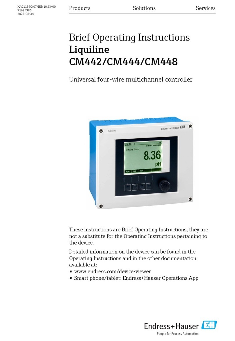
Endress+Hauser Liquiline CM442 User manual
Other Endress+Hauser Controllers manuals
Endress+Hauser
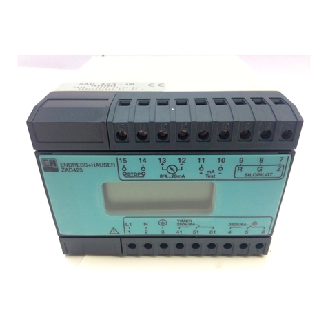
Endress+Hauser ZAD 423 User manual
Endress+Hauser
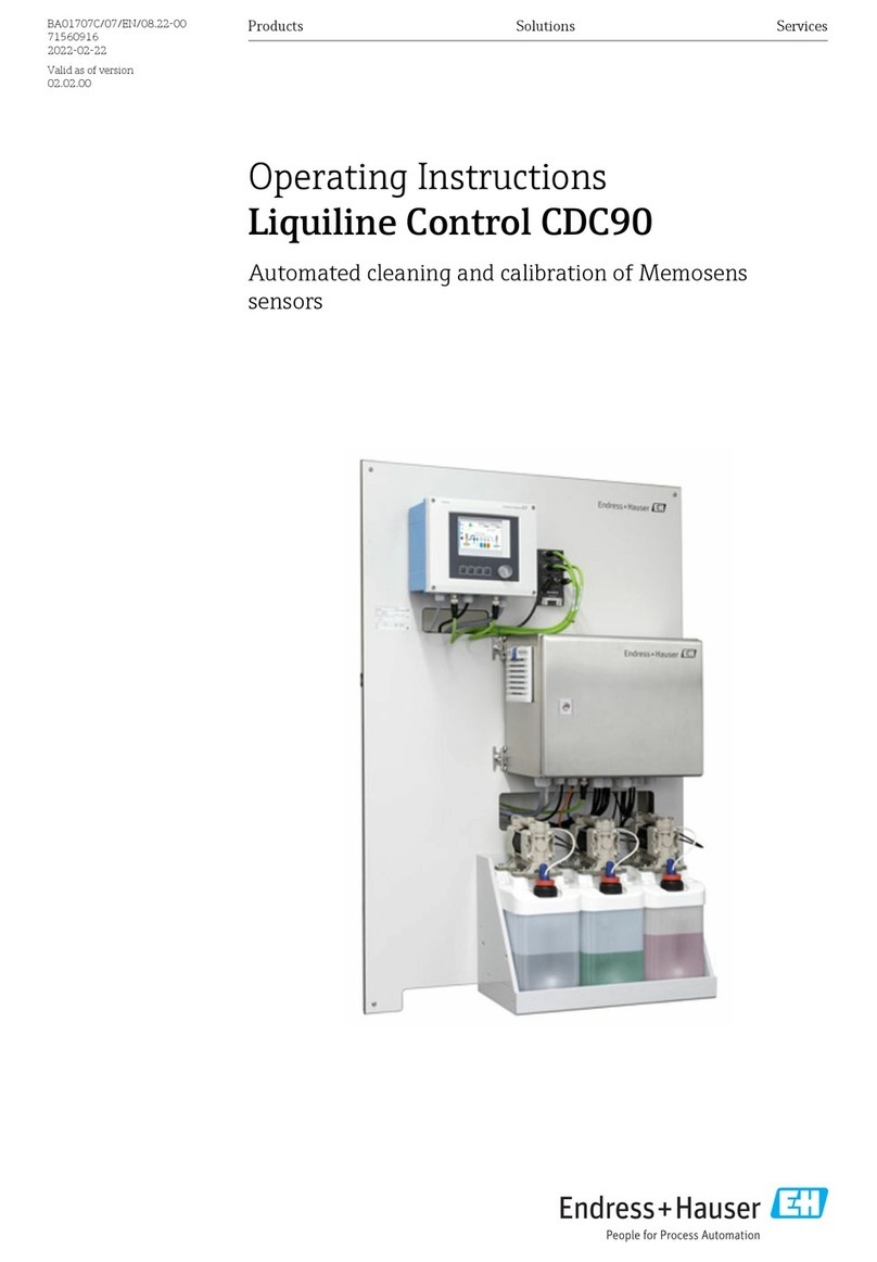
Endress+Hauser Liquiline Control CDC90 User manual
Endress+Hauser
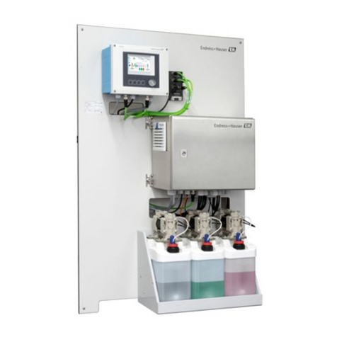
Endress+Hauser Liquiline Control CDC90 Technical specifications
Endress+Hauser
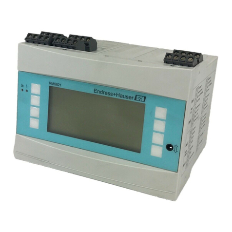
Endress+Hauser RMS621 User manual

Endress+Hauser
Endress+Hauser Liquiline CM44P User manual
Endress+Hauser
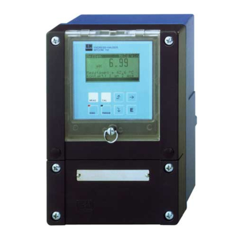
Endress+Hauser Mycom CPM 152 User manual
Endress+Hauser
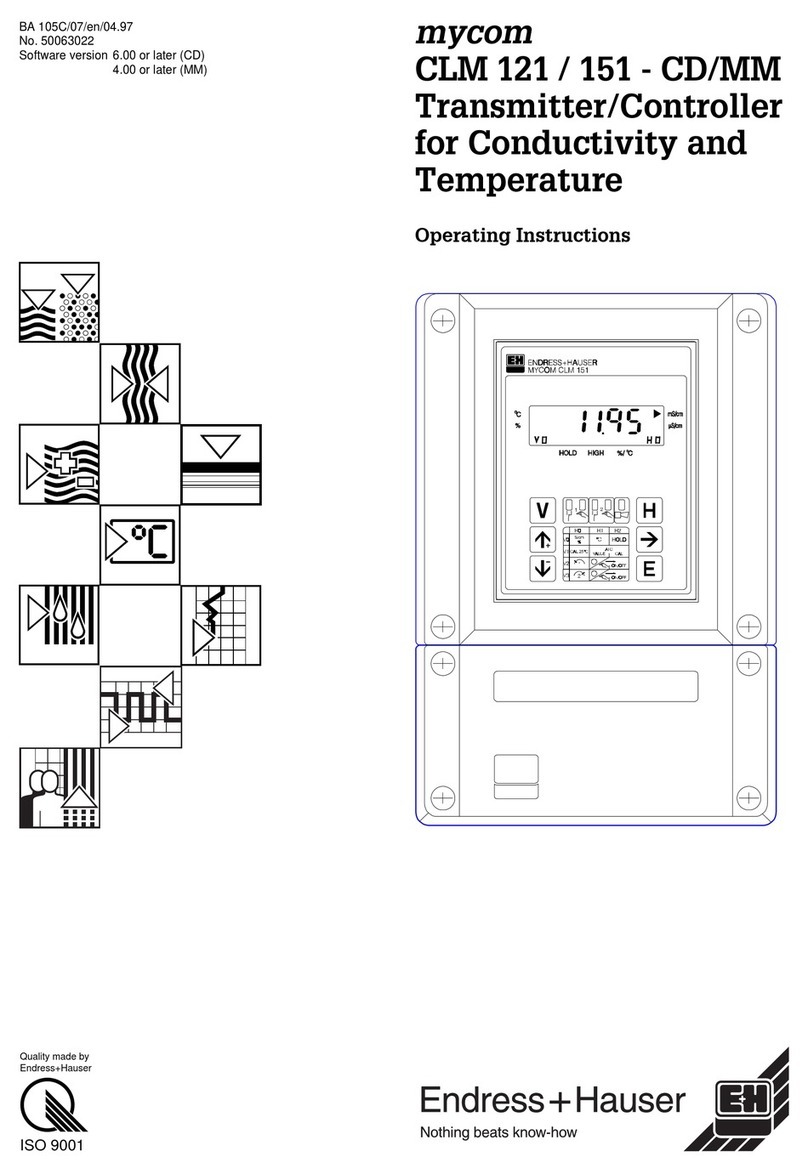
Endress+Hauser mycom CLM 121 User manual

Endress+Hauser
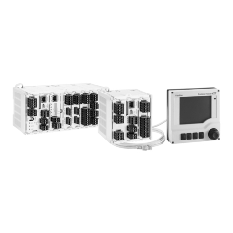
Endress+Hauser Liquiline CM442R Technical specifications
Endress+Hauser
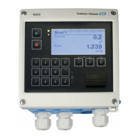
Endress+Hauser RA33 User manual

Endress+Hauser
Endress+Hauser RA33 User manual

Endress+Hauser
Endress+Hauser Liquiline CM442R Technical specifications
Endress+Hauser
Endress+Hauser Liquiline CM442R Manual
Endress+Hauser
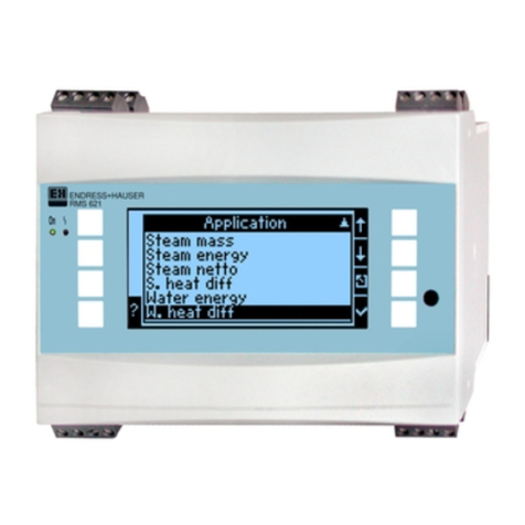
Endress+Hauser RMS621 User manual

Endress+Hauser
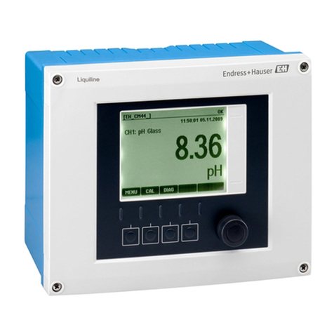
Endress+Hauser Liquiline CM442R User manual
Endress+Hauser
Endress+Hauser Liquiline CM442 User manual
Endress+Hauser
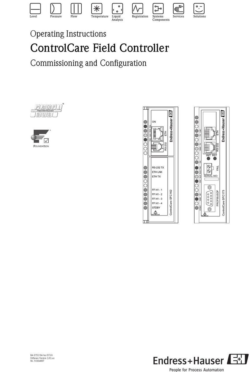
Endress+Hauser ControlCare SFC173 User manual

Endress+Hauser
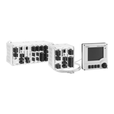
Endress+Hauser Liquiline CM442 User manual
Endress+Hauser
Endress+Hauser Liquiline CM442R User manual
Endress+Hauser
Endress+Hauser Liquiline CM442 Technical specifications

Endress+Hauser
Endress+Hauser Liquiline CM442R Technical specifications
Popular Controllers manuals by other brands

Digiplex
Digiplex DGP-848 Programming guide

YASKAWA
YASKAWA SGM series user manual

Sinope
Sinope Calypso RM3500ZB installation guide

Isimet
Isimet DLA Series Style 2 Installation, Operations, Start-up and Maintenance Instructions

LSIS
LSIS sv-ip5a user manual

Airflow
Airflow Uno hab Installation and operating instructions


