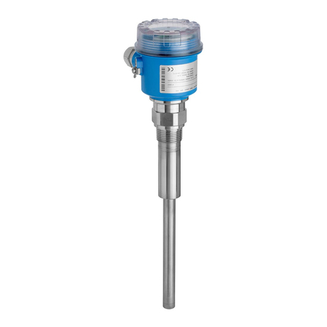
Gammapilot M FMG60 FOUNDATION Fieldbus Table of contents
Endress+Hauser 5
Table of contents
1 About this document ................ 7
1.1 Document function ..................... 7
1.2 Symbols used .......................... 7
1.2.1 Safety symbols .................. 7
1.2.2 Electrical symbols ................ 7
1.2.3 Tool symbols .................... 7
1.2.4 Symbols for
certain types of information ......... 8
1.2.5 Symbols in graphics ............... 8
2 Basic safety instructions ............ 9
2.1 Requirements for the personnel ............ 9
2.2 Designated use ........................ 9
2.3 Installation, commissioning and operation .... 9
2.4 Hazardous area ........................ 9
2.5 Radiation protection ................... 10
2.5.1 Basic radiation protection
guidelines ..................... 10
2.6 Workplace safety ...................... 11
2.7 Operational safety ..................... 11
2.8 Product safety ........................ 11
3 Product description ................ 13
3.1 Product design ........................ 13
3.1.1 Components of the FMG60 ........ 13
3.2 Nameplates .......................... 14
3.2.1 Device nameplate ............... 14
3.2.2 Supplementary nameplate
(examples) .................... 14
3.3 Scope of delivery ...................... 14
3.4 Accompanying documentation ............ 15
3.4.1 Operating Instructions
(BA00236F/00/EN) ............. 15
3.4.2 Description of Device Functions
(BA00287F/00/EN) ............. 15
3.4.3 Safety instructions ............... 15
3.5 Certificates and approvals ............... 15
3.6 Registered trademarks .................. 15
4 Installation ....................... 16
4.1 Incoming acceptance, product identification,
transport, storage ..................... 16
4.1.1 Incoming acceptance ............. 16
4.1.2 Product identification ............ 16
4.1.3 Transport ..................... 16
4.1.4 Storage ....................... 16
4.2 Installation conditions .................. 16
4.2.1 Dimensions, weight .............. 16
4.2.2 Installation conditions for level
measurement .................. 17
4.2.3 Installation conditions for point level
detection ..................... 18
4.2.4 Installation conditions for density
and concentration measurements ... 19
4.2.5 Empty pipe detection ............. 21
4.2.6 Installation conditions for flow
measurement .................. 21
4.3 Water cooling ........................ 22
4.3.1 Mounting position and position of
the cooling water nozzles ......... 23
4.3.2 Required flow .................. 24
4.4 Post-installation check .................. 24
5 Wiring ............................ 26
5.1 Connection compartments ............... 26
5.2 Cable entries ......................... 26
5.3 Terminal assignment ................... 27
5.4 Fieldbus connectors .................... 29
5.4.1 Pin assignment for connector M12 .. 29
5.4.2 Pin assignment for connector 7/8" ... 29
5.5 Foundation Fieldbus cable specifications ..... 29
5.6 Foundation Fieldbus terminal voltage ....... 30
5.7 Potential equalization .................. 30
5.8 Wiring in connection compartment 1 ....... 31
5.9 Wiring in connection compartment 2 ....... 32
5.10 Connecting the remote display and operating
unit FHX40 .......................... 32
5.11 Wiring for cascade mode ................ 34
5.12 Post-connection check .................. 34
6 Operation ......................... 35
6.1 Overview of the operating options ......... 35
6.1.1 FOUNDATION Fieldbus (FF) ....... 35
6.2 Display operation ...................... 36
6.2.1 Display and operating elements ..... 36
6.2.2 The operating menu ............. 37
6.3 Alternative operation options ............. 39
6.3.1 Operation via Field Xpert SFX100 ... 39
6.3.2 Operation with FieldCare .......... 39
6.4 Locking/unlocking configuration .......... 40
6.4.1 Software locking ................ 40
6.4.2 Hardware locking ............... 40
6.5 Resetting to the default configuration ....... 40
6.6 FOUNDATION Fieldbus interface .......... 41
6.6.1 System architecture .............. 41
6.6.2 Hardware settings ............... 41
6.6.3 Network configuration ........... 42
6.6.4 Block model of the Gammapilot M ... 43
6.6.5 Resource block ................. 44
6.6.6 Transducer block ................ 45
6.6.7 Diagnostic block ................ 49
6.6.8 Display block ................... 49
6.6.9 Analog Input block .............. 50
6.6.10 Commissioning checklist .......... 53
6.6.11 Start index list .................. 54
