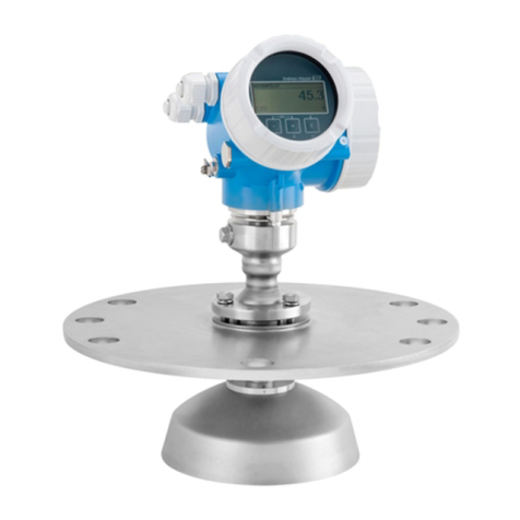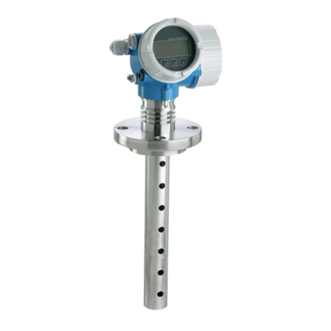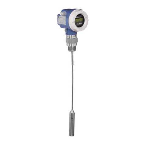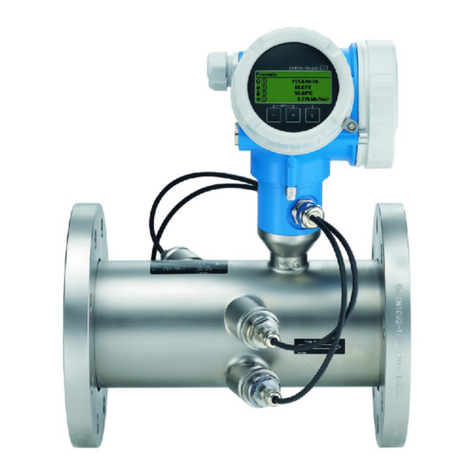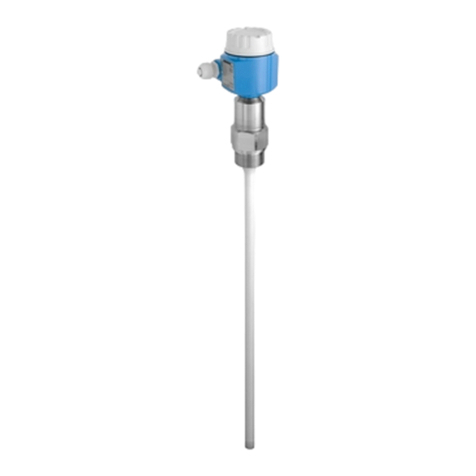
Levelflex FMP51, FMP52, FMP54 Table of contents
Endress+Hauser 3
Table of contents
1 Important document information ..... 5
1.1 About this document ..................... 5
1.1.1 Document function ................. 5
1.1.2 Additional standard documentation on the
device .......................... 5
1.1.3 Safety Instructions (XA) for Levelflex
FMP51, FMP52, FMP54 ............. 5
1.2 Document conventions .................... 6
1.2.1 Safety symbols .................... 6
1.2.2 Electrical symbols .................. 7
1.2.3 Tool symbols ..................... 7
1.2.4 Symbols for certain types of information ... 7
1.2.5 Symbols in graphics ................. 8
2 Basic safety instructions .............. 9
2.1 Requirements concerning the staff ............ 9
2.2 Designated use .......................... 9
2.3 Workplace safety ........................ 9
2.4 Operational safety ....................... 10
2.5 Product safety ......................... 10
3 Product description ................ 11
3.1 Product design ......................... 11
3.1.1 Compact device Levelflex ............ 11
3.1.2 Electronics housing ................ 12
3.2 Registered trademarks .................... 12
3.3 Patents .............................. 12
4 Incoming acceptance and product
identification ...................... 14
4.1 Incoming acceptance .................... 14
4.2 Product identification .................... 15
4.2.1 Nameplate ...................... 16
4.2.2 Product structure FMP51, FMP52,
FMP54 ........................ 16
5 Storage, Transport ................. 25
5.1 Storage conditions ...................... 25
5.2 Transport product to the measuring point ....... 25
6 Mounting .......................... 26
6.1 Mounting dimensions .................... 26
6.1.1 Dimensions of the electronics housing ... 26
6.1.2 Dimensions of the mounting bracket .... 27
6.1.3 FMP51: Dimensions of process connection
(G¾,NPT¾) and probe .............. 28
6.1.4 FMP51: Dimensions of process connection
(G1½,NPT1½,flange) and probe ....... 29
6.1.5 FMP52: Dimensions of process connection
and probe ....................... 31
6.1.6 FMP54: Dimensions of process connection
and probe ....................... 32
6.2 Mounting requirements ................... 33
6.2.1 Suitable mounting position ........... 33
6.2.2 Applications with restricted mounting
space .......................... 34
6.2.3 Notes on the mechanical load of the
probe .......................... 35
6.2.4 Notes on the process connection ....... 37
6.2.5 Securing the probe ................. 40
6.2.6 Special mounting conditions .......... 42
6.3 Mounting the device ..................... 50
6.3.1 Required mounting tools ............. 50
6.3.2 Preparing the device for mounting ...... 50
6.3.3 FMP54 with gas phase compensation:
Mounting the probe rod ............. 51
6.3.4 Mounting the device ............... 52
6.3.5 Mounting the "Sensor remote" version ... 53
6.3.6 Turning the transmitter housing ....... 55
6.3.7 Turning the display module ........... 56
6.4 Post-installation check .................... 56
7 Electrical connection ............... 57
7.1 Connection options ...................... 57
7.1.1 PROFIBUS PA / FOUNDATION
Fieldbus ........................ 57
7.1.2 Connection examples for the switch
output ......................... 58
7.2 Connection options ...................... 58
7.2.1 Cable specification ................. 58
7.2.2 Cable diameter and cross-section of the
strands ......................... 58
7.2.3 Overvoltage protection .............. 59
7.3 Connection data ........................ 59
7.3.1 PROFIBUS PA .................... 59
7.4 Connecting the measuring device ............ 60
7.5 Post-connection check ................... 62
8 Operating options .................. 63
8.1 Overview ............................ 63
8.1.1 On-site operation .................. 63
8.1.2 Operation with remote display and
operating module FHX50 ............ 63
8.1.3 System integration via PROFIBUS PA .... 63
8.2 The operating menu ..................... 65
8.2.1 Structure ....................... 65
8.2.2 Submenus and user roles ............ 66
8.2.3 Locking the menu ................. 66
8.3 Display and operating module .............. 68
8.3.1 Display appearance ................ 68
8.3.2 Operating elements ................ 71
8.3.3 Entering numbers and text ........... 72
8.3.4 Envelope curve on the display and
operating module ................. 74

