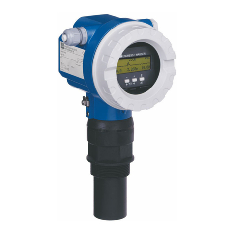
TopCal S CPC 300
Endress+Hauser 3
Table of Contents
1 Safety instructions . . . . . . . . . . . . . . . . . . . 5
1.1 Designated use . . . . . . . . . . . . . . . . . . . . . . . . . . . . 5
1.2 Installation, commissioning, operation . . . . . . . . . . 5
1.3 Operational safety . . . . . . . . . . . . . . . . . . . . . . . . . . 5
1.4 Return . . . . . . . . . . . . . . . . . . . . . . . . . . . . . . . . . . . 6
1.5 Safety symbols . . . . . . . . . . . . . . . . . . . . . . . . . . . . . 6
2 Identification . . . . . . . . . . . . . . . . . . . . . . . . 8
2.1 Instrument designation . . . . . . . . . . . . . . . . . . . . . . 8
2.1.1 Nameplate . . . . . . . . . . . . . . . . . . . . . . . . . 8
2.1.2 Product structure . . . . . . . . . . . . . . . . . . . . 9
2.2 Scope of delivery . . . . . . . . . . . . . . . . . . . . . . . . . . 10
2.3 Certificates and approvals . . . . . . . . . . . . . . . . . . . 10
3 Installation . . . . . . . . . . . . . . . . . . . . . . . . . 11
3.1 Incoming acceptance, transport, storage . . . . . . . . 11
3.2 Installation conditions . . . . . . . . . . . . . . . . . . . . . . 11
3.2.1 Installation dimensions . . . . . . . . . . . . . . . 12
3.2.2 Assembly mounting . . . . . . . . . . . . . . . . . . 12
3.3 Installation instructions . . . . . . . . . . . . . . . . . . . . . 13
3.3.1 Measuring system . . . . . . . . . . . . . . . . . . . 13
3.3.2 Wall mounting . . . . . . . . . . . . . . . . . . . . . 13
3.3.3 Post mounting and panel mounting . . . . . . 15
3.4 Installation check . . . . . . . . . . . . . . . . . . . . . . . . . 16
4 Wiring and pneumatic connection
of Topclean S . . . . . . . . . . . . . . . . . . . . . . . 17
4.1 Connection of required electric lines . . . . . . . . . . . 17
4.1.1 Power supply and communication line
of Mycom and CPG30 . . . . . . . . . . . . . . . . 17
4.1.2 CYR10 injector . . . . . . . . . . . . . . . . . . . . . 19
4.1.3 Analogue pH glass electrodes and
ISFET sensors . . . . . . . . . . . . . . . . . . . . . . 20
4.1.4 Digital pH sensors with
Memosens technology . . . . . . . . . . . . . . . . 25
4.2 Connecting optional electric lines . . . . . . . . . . . . . 26
4.2.1 Mycom current outputs and relays . . . . . . . 26
4.2.2 External inputs (PCS to CPG30) and
outputs (CPG30 to PCS) . . . . . . . . . . . . . . 28
4.2.3 External inputs PCS to Mycom . . . . . . . . . 29
4.2.4 External valve for sealing water,
steam, etc. to CPG30 . . . . . . . . . . . . . . . . 30
4.2.5 Inductive limit position switches . . . . . . . . 31
4.3 Topclean S hosing . . . . . . . . . . . . . . . . . . . . . . . . . 33
4.3.1 Compressed air . . . . . . . . . . . . . . . . . . . . . 33
4.3.2 CPA471 / 472 / 475 assemblies with
pneumatic limit position switches . . . . . . . 34
4.3.3 CPA471 / 472 / 475 assemblies with
inductive limit position switches . . . . . . . . 35
4.3.4 CPA473 / 474 assemblies with
pneumatic limit switches . . . . . . . . . . . . . . 36
4.3.5 CPA473 / 474 assemblies with
inductive limit switches . . . . . . . . . . . . . . . 37
4.4 Connection diagram Non-Ex . . . . . . . . . . . . . . . . . 38
4.5 Connection compartment sticker CPG30 . . . . . . . . 39
4.6 Connection compartment sticker Mycom . . . . . . . . 40
4.7 Post connection check . . . . . . . . . . . . . . . . . . . . . . 41
5 Operation . . . . . . . . . . . . . . . . . . . . . . . . . . 42
5.1 Display and operating elements . . . . . . . . . . . . . . . 42
5.1.1 Display reading/symbols . . . . . . . . . . . . . . 42
5.1.2 Key assignment . . . . . . . . . . . . . . . . . . . . . 42
5.1.3 Operation of the service switch . . . . . . . . . 43
5.1.4 Measuring menus . . . . . . . . . . . . . . . . . . . 44
5.1.5 Data log . . . . . . . . . . . . . . . . . . . . . . . . . . 44
5.1.6 Operation access authorisation . . . . . . . . . . 45
5.1.7 Description of the menu editor types . . . . . 46
5.1.8 Factory settings . . . . . . . . . . . . . . . . . . . . . 46
5.2 Replaceable memory . . . . . . . . . . . . . . . . . . . . . . . 47
6 Commissioning . . . . . . . . . . . . . . . . . . . . 48
6.1 Special features for measurement with
digital sensors with Memosens technology . . . . . . . 48
6.2 Special features for measurement with
ISFET sensors . . . . . . . . . . . . . . . . . . . . . . . . . . . . 49
6.3 Installation and function check control . . . . . . . . . 49
6.4 Switching on the device . . . . . . . . . . . . . . . . . . . . 49
6.4.1 First commissioning . . . . . . . . . . . . . . . . . . 50
6.5 First start up . . . . . . . . . . . . . . . . . . . . . . . . . . . . . 51
6.5.1 Configuring Clean programme
(via automatic function) . . . . . . . . . . . . . . . 54
6.6 Description of functions . . . . . . . . . . . . . . . . . . . . . 56
6.6.1 Set up 1 – Sensor input . . . . . . . . . . . . . . . 56
6.6.2 Set up 1 – Display . . . . . . . . . . . . . . . . . . . 57
6.6.3 Set up 1 – Access codes . . . . . . . . . . . . . . 58
6.6.4 Set up 1 – Current outputs . . . . . . . . . . . . . 59
6.6.5 Set up 1 – Relays . . . . . . . . . . . . . . . . . . . . 61
6.6.6 Set up 1 – Temperature . . . . . . . . . . . . . . . 62
6.6.7 Set up 1 – Alarm . . . . . . . . . . . . . . . . . . . . 65
6.6.8 Set up 1 – Hold . . . . . . . . . . . . . . . . . . . . . 66
6.6.9 Set up 1 – Calibration . . . . . . . . . . . . . . . . 67
6.6.10 Set up 2 – Data log . . . . . . . . . . . . . . . . . . 72
6.6.11 Set up 2 – Check systems . . . . . . . . . . . . . 73
6.6.12 Set up 2 – Controller settings . . . . . . . . . . . 74
6.6.13 Set up 2 – Limit switch . . . . . . . . . . . . . . . 86
6.6.14 Set up 2 - Controller quick adjustment . . . . 87
6.6.15 Set up 2 – Topclean S . . . . . . . . . . . . . . . . 88
6.6.16 Set up 2 – Chemoclean . . . . . . . . . . . . . . . 98
6.6.17 Manual operation . . . . . . . . . . . . . . . . . . 102
6.6.18 Diagnosis . . . . . . . . . . . . . . . . . . . . . . . . . 104
6.6.19 Calibration . . . . . . . . . . . . . . . . . . . . . . . 112
