Endress+Hauser CYR52 User manual

Products Solutions Services
BA01300C/07/EN/02.14
71261315
Operating Instructions
CYR52
Ultrasonic cleaning

Document information
Warnings
The structure, signal words and safety colors of the signs comply with the specifications of ANSI
Z535.6 ("Product safety information in product manuals, instructions and other collateral
materials").
Symbols used
Safety message structure Meaning
DANGER
!
Causes (/consequences)
Consequences if safety message
is not heeded
‣Corrective action
This symbol alerts you to a dangerous situation.
Failure to avoid the situation will result in a fatal or serious
injury.
WARNING
!
Causes (/consequences)
Consequences if safety message
is not heeded
‣Corrective action
This symbol alerts you to a dangerous situation.
Failure to avoid the situation can result in a fatal or serious
injury.
CAUTION
!
Causes (/consequences)
Consequences if safety message
is not heeded
‣Corrective action
This symbol alerts you to a dangerous situation.
Failure to avoid this situation can result in minor or more
serious injuries.
NOTICE
Cause/situation
Consequences if safety message
is not heeded
‣Action/note
This symbol alerts you to situations that can result in
damage to property and equipment.
Additional information, tips
Permitted or recommended
Forbidden or not recommended

Endress+Hauser
CYR52
Table of contents
1 Basic safety instructions . . . . . . 4
1.1 Requirements for personnel . . . . . . . . . . . 4
1.2 Designated use . . . . . . . . . . . . . . . . . . . . . . 4
1.3 Workplace safety . . . . . . . . . . . . . . . . . . . . 4
1.4 Operational safety . . . . . . . . . . . . . . . . . . . 4
1.5 Product safety . . . . . . . . . . . . . . . . . . . . . . 5
2 Incoming acceptance and
product identification . . . . . . . . 6
2.1 Incoming acceptance . . . . . . . . . . . . . . . . . 6
2.2 Scope of delivery . . . . . . . . . . . . . . . . . . . . 6
2.3 Product identification . . . . . . . . . . . . . . . . 7
2.4 Certificates and approvals . . . . . . . . . . . . 7
3 Installation . . . . . . . . . . . . . . . . . 8
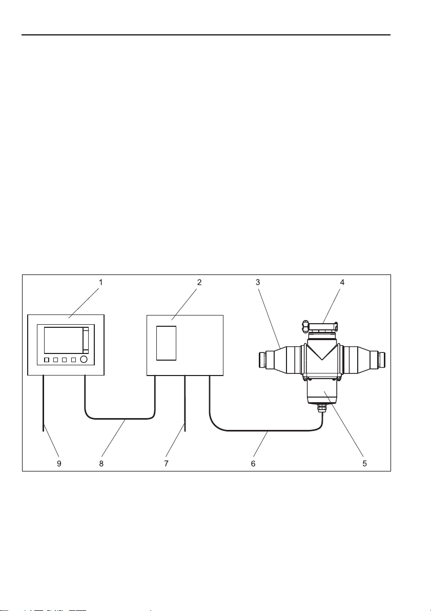
3.1 Quick installation guide . . . . . . . . . . . . . . 8
3.2 Installation conditions . . . . . . . . . . . . . . 13
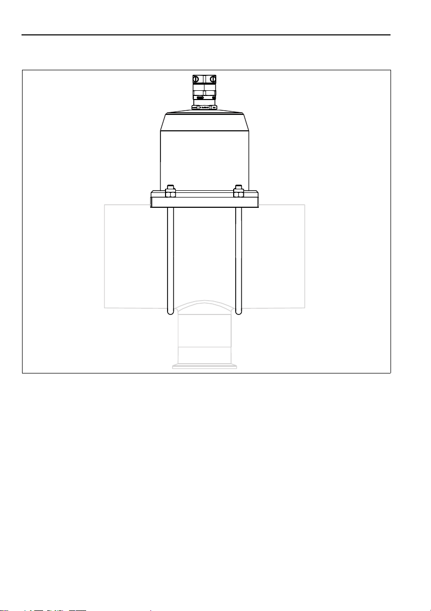
3.3 Mounting the ultrasonic transducer . . . 17
3.4 Mounting the ultrasonic generator . . . . 18
3.5 Post-installation check . . . . . . . . . . . . . . 21
4 Electrical connection . . . . . . . . 22
4.1 Wiring . . . . . . . . . . . . . . . . . . . . . . . . . . . 22
4.2 Post-connection check . . . . . . . . . . . . . . 23
5 Commissioning. . . . . . . . . . . . . 24
5.1 Function check . . . . . . . . . . . . . . . . . . . . . 24
5.2 Configuration . . . . . . . . . . . . . . . . . . . . . . 24
6 Diagnostics and troubleshooting
25
7 Maintenance. . . . . . . . . . . . . . . 26
7.1 Cleaning the transmitter, ultrasonic
transducer and ultrasonic generator . . . 26
8 Repair. . . . . . . . . . . . . . . . . . . . . 27
8.1 Spare part kits . . . . . . . . . . . . . . . . . . . . . 27
8.2 Return . . . . . . . . . . . . . . . . . . . . . . . . . . . . 27
8.3 Disposal . . . . . . . . . . . . . . . . . . . . . . . . . . . 27
9 Accessories . . . . . . . . . . . . . . . . 28
10 Technical data. . . . . . . . . . . . . . 29
10.1 Output . . . . . . . . . . . . . . . . . . . . . . . . . . . . 29
10.2 Power supply . . . . . . . . . . . . . . . . . . . . . . . 29
10.3 Environment . . . . . . . . . . . . . . . . . . . . . . . 29
10.4 Mechanical construction . . . . . . . . . . . . . 30
Index. . . . . . . . . . . . . . . . . . . . . . 31

Basic safety instructions CYR52
4Endress+Hauser
1 Basic safety instructions
1.1 Requirements for personnel
‣Installation, commissioning, operation and maintenance of the measuring system must only
be carried out by specially trained technical personnel.
‣The technical personnel must be authorized for the specified activities by the system
operator.
‣Electrical connection must only be carried out by a certified electrician.
‣Technical personnel must have read and understood these Operating Instructions and must
adhere to them.
‣Faults at the measuring point may only be rectified by authorized and specially trained
personnel.
Repairs not described in the enclosed Operating Instructions may only be carried out
directly at the manufacturer’s or by the service organization.
1.2 Designated use
The CYR52 ultrasonic cleaning unit is used to clean turbidity sensors in liquid medium that are
installed in pipes.
Any other use than the one described here compromises the safety of persons and the entire
measuring system and is therefore not permitted.
The manufacturer is not liable for damage resulting from improper or non-designated use.
1.3 Workplace safety
As the user, you are responsible for complying with the following safety conditions:
• Explosion protection guidelines (only devices approved for use in explosion hazardous areas)
• Installation instructions
• Local prevailing standards and regulations
Electromagnetic compatibility
The product has been tested for electromagnetic compatibility in accordance with the applicable
European standards for industrial applications.
The electromagnetic compatibility indicated only applies to a product that has been connected
in accordance with the instructions in these Operating Instructions.
1.4 Operational safety
‣Before commissioning the entire measuring point, make sure all the connections are correct.
Ensure that electrical cables and hose connections are not damaged.
‣Do not operate damaged products, and secure them against unintentional commissioning.
Label and identify the damaged product as defective.
‣If faults cannot be rectified, you must take the products out of service and secure them
against unintentional commissioning.

CYR52 Basic safety instructions
Endress+Hauser 5
1.5 Product safety
The product is designed to meet state-of-the-art safety requirements, has been tested and left
the factory in a condition in which it is safe to operate.
Relevant regulations and European standards have been observed.

Incoming acceptance and product identification CYR52
6Endress+Hauser
2 Incoming acceptance and product identification
2.1 Incoming acceptance
• Make sure the packaging is undamaged!
• Notify the supplier of any damage to the packaging. Keep the damaged packaging until the
matter has been settled.
• Make sure the contents are not damaged!
• Notify the supplier of any damage to the delivery contents. Keep the damaged products until
the matter has been settled.
• Check the delivery to make sure nothing is missing. Compare it against the shipping
documents and your order.
• Pack the product for storage and transportation in such a way that it is reliably protected
against impact and moisture. The original packaging offers the best protection. Furthermore,
the permitted ambient conditions must also be observed (see "Technical data").
• If you have any questions, contact your supplier or your local sales center.
2.2 Scope of delivery
The scope of delivery of the ultrasonic cleaning system comprises:
• 1 Ultrasonic generator
• 1 Ultrasonic transducer
• Mounting material depending on the order version
• 1 Set of Operating Instructions BA01300C/07/EN
If you have any questions, please contact your supplier or your local sales center.

CYR52 Incoming acceptance and product identification
Endress+Hauser 7
2.3 Product identification
2.3.1 Nameplate
You can find the following information on the nameplate:
• Manufacturer details
•Ordercode
• Serial number
• Operating conditions
• Safety information symbols
Compare the order code on the nameplate with your order.
2.3.2 Identifying the product
The order code and serial number of your device can be found in the following locations:
• On the nameplate
• In the shipping documents
To find out the version of your product, enter the order code indicated on the nameplate in
the search screen at the following address:
www.products.endress.com/order-ident
2.4 Certificates and approvals
2.4.1 4mark
Declaration of Conformity
The product meets the requirements of the harmonized European standards.
As such, it complies with the legal specifications of the EC directives.
The manufacturer confirms successful testing of the product by affixing to it the 4mark.

Installation CYR52
8Endress+Hauser
3Installation
3.1 Quick installation guide
Proceed as follows for the full installation of the measuring point:
• Install the ultrasonic transducer face to face with the turbidity sensor (see the "Mounting the
ultrasonic transducer" section).
• Install the ultrasonic generator (see the "Mounting the ultrasonic generator" section).
• Connect the ultrasonic transducer and the ultrasonic generator as illustrated in the graphic in
the "Electrical connection" section.
• Put the ultrasonic cleaning system into operation as described in the "Commissioning" section.
3.1.1 Overview
The complete ultrasonic cleaning system comprises:
• Ultrasonic generator
• Ultrasonic transducer
• Assembly or pipe with turbidity sensor
• Liquiline CM44x transmitter
a0022749
Fig. 1: Ultrasonic cleaning with Flowfit CUA252 assembly
1
2
3
4
5
Liquiline CM44x transmitter
Ultrasonic generator
Flowfit CUA252 flow assembly
Clamp connection for turbidity sensor
Ultrasonic transducer
6
7
8
9
Power supply cable for ultrasonic transducer
Mains voltage cable for ultrasonic generator
Control cable
Mains voltage cable for transmitter

CYR52 Installation
Endress+Hauser 9
3.1.2 Installation options
With Flowfit CUA252 flow assembly
a0022751
Fig. 2: Ultrasonic transducer on Flowfit CUA252 assembly

Installation CYR52
10 Endress+Hauser
With Flowfit CUA262 flow assembly
a0022752
Fig. 3: Ultrasonic transducer on Flowfit CUA262 assembly

CYR52 Installation
Endress+Hauser 11
With assembly of CUS31
a0022754
Fig. 4: Ultrasonic transducer with assembly of CUS31

Installation CYR52
12 Endress+Hauser
Mounted on a pipe
a0022757
Fig. 5: Ultrasonic transducer mounted on a pipe

CYR52 Installation
Endress+Hauser 13
3.2 Installation conditions
3.2.1 Ultrasonic transducer
a0022750
Fig. 6: Dimensions in mm (inch) for CUA252 and CUA262
In the case of the ultrasonic transducer factor in a clearance of approx. 100 mm (4 inch)
above the cable gland for the power supply cable.

Installation CYR52
14 Endress+Hauser
a0022753
Fig. 7: Dimensions in mm (inch) for assembly of CUS31

CYR52 Installation
Endress+Hauser 15
a0022756
Fig. 8: Dimensions in mm (inch) for pipe mounting

Installation CYR52
16 Endress+Hauser
3.2.2 Ultrasonic generator
a0022755
Fig. 9: Dimensions in mm (inch)
199 (7.38)
162 (6.38)
237 (9.33)
194 (7.64)
128 (5.04)

CYR52 Installation
Endress+Hauser 17
3.3 Mounting the ultrasonic transducer
The ultrasonic transducer is secured to assemblies with two brackets that are supplied, and to
pipes with two worm drive hose clips that are supplied.
a0022759
Fig. 10: Ultrasonic contact paste(1)
Mount the ultrasonic transducer as follows:
1. Using the cleaning cloth (scope of delivery) clean the contact surface of the ultrasonic
transducer and the contact surface of the assembly or pipe.
2. Coat the contact surface of the ultrasonic transducer (å10, item 1) with a 5 mm
(0.2")stripe ultrasonic contact paste.
3. Mount the ultrasonic transducer face to face with the turbidity sensor.
4. In the case of pipes:
Tighten the two worm drive hose clips with a torque of 2.5 Nm (1.85 lbf ft).
In the case of assemblies:
Tighten the nuts of the brackets with a torque of 2 Nm (1.47 lbf ft).

Installation CYR52
18 Endress+Hauser
3.4 Mounting the ultrasonic generator
3.4.1 Mounting plate
a0012426
Fig. 11: Dimensions in mm (inch)
3.4.2 Weather protection cover (optional)
NOTICE
Effect of climatic conditions (rain, snow, direct sun etc.)
Impaired operation to complete failure of the ultrasonic generator
‣When installing outside, always use the weather protection cover (accessory)
a0019166
Fig. 12: Weather protection cover for ultrasonic generator
320 (12.6)
270 (10.6)
300 (11.8)
mm (inch)

CYR52 Installation
Endress+Hauser 19
3.4.3 Mounting the ultrasonic generator
Post mounting
You require the post mounting kit (optional) to mount the unit on a pipe, post or railing (square
or round, clamping range 20 to 61 mm (0.79 to 2.40")).
a0012665
Fig. 13: Post mounting
1
2
3
4
Weather protection cover (optional)
Post mounting plate (post mounting)
Spring washers and nuts (post mounting kit)
Pipe clamps (post mounting kit)
5
6
7
8
Spring washers and nuts (post mounting kit)
Pipe or post
Mounting plate
Threaded rods /post mounting kit)
a0012666
Fig. 14: Post mounting
a0022760
Fig. 15: Attach the device and click it into place

Installation CYR52
20 Endress+Hauser
Rail mounting
a0012668
Fig. 16: Rail mounting
1
2
3
4
5
Weather protection cover (optional)
Post mounting plate (post mounting)
Spring washers and nuts (post mounting kit)
Pipe clamps (post mounting kit)
Spring washers and nuts (post mounting kit)
6
7
8
9
Pipe or railing /round/square)
Mounting plate
Threaded rods /post mounting kit)
Screws (post mounting kit)
a0012669
Fig. 17: Rail mounting
a0022762
Fig. 18: Attach the device and click it into place
2.
1.
Other manuals for CYR52
1
Table of contents
Other Endress+Hauser Other manuals