Endura EVC User manual
Single Unit In-Vehicle Charger
FOR TWO-WAY RADIO BATTERIES
User Manual
For EVC Models
IN-VEHICLE
CHARGERS
EVC


Topic Page
Introduction 1
Important 2
Caution 3
Features 4 - 5
Installation 6
Charging A Radio Battery 7 - 8
USB Charging Port 8
Status LED Summary 9
Fault Conditions And Advisements 10 - 11
Specifications 12
Warranty 13
Optional Accessories 14
Installation Notes 15
Table of Contents

1
Introduction
Thank you for purchasing an Endura EVC in-vehicle charger. This rugged product features
advanced charging technology and is designed for rapid charging two-way radio batteries from
a 12V – 24V source in a vehicle. EVC models are radio specific and provide a precision fit with
the battery. The model you have purchased will charge Li-Ion / LiPo batteries only or Li-Ion, LiPo
and NiMH batteries based on the batteries available for your radio. If you have questions about
your EVC model, contact your Power Products dealer or call 800-529-1618.

2
Important
1. Read all Caution statements below and this User Manual before attempting to install the
EVC or charge a battery.
2. Check to make sure the EVC model is compatible with your radio battery and battery
chemistry before installing.
3. Always charge new batteries completely before initial use. Recycle batteries when they
can no longer be used.
4. For best performance, charge NiCd and NiMH batteries when they are fully discharged.

3
1. Do not charge a battery unless it is designed with overcharge protection.
2. Do not discard unwanted batteries in the trash or incinerate. Batteries exposed to fire or
excessive heat may explode.
3. Install the EVC where it will be protected from rain or moisture.
4. Make sure contacts on the radio holder and battery are clean. Do not allow wire or metal
objects to touch the contacts.†
5. Do not open or make any modifications to the EVC. Use only the DC power cable supplied.
6. Always secure the radio (or battery) in the radio holder with the tie-down strap before the
vehicle, trailer, or train goes in motion.
7. Make sure that the tie-down strap securely holds the radio or battery, but is not too tight.
An over-tensioned strap could cause injury when released.
Caution
4
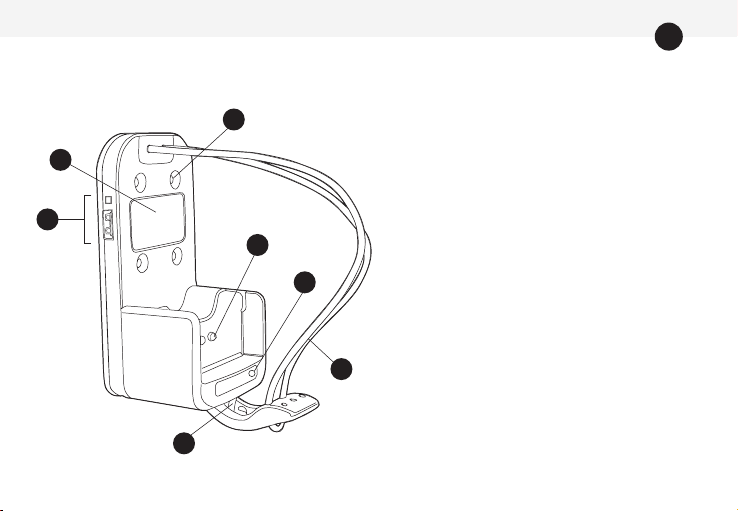
EVC Features
1. Status LED information.
2. Holes for fastening to dash or mounting
bracket (see Optional Accessories).
3. Charging contacts.
4. Status LED (radio battery).
5. Tie-down strap.
†
6. Retaining hook for connecting
tie-down strap.
7. USB charging port and power-on LED.
6
5
4
2
3
7
1
† Some EVC models have a fabric strap with grommets in place of the elastic cord.

5
9
EVC Features (continued)
8
8. Screws and spacers for fastening EVC
to vehicle.
9. Connection point for DC power cable.
10. DC power cable (EVC-HW).
10

6
Installation
Before installing the EVC, confirm that the model is compatible with the radio battery you want to
charge and the battery’s chemistry.
1. Select an area in the vehicle to mount the charger. The EVC’s compact size allows it to be installed in
areas where other in-vehicle chargers will not fit.
2. Run the DC power cable from the charger and connect it to the vehicle’s 12V or 24V source. Fully
insert the DC cable plug into the connection point on the bottom of the charger.
3. Place the battery in the charger to confirm it will properly charge. If there are no issues, fasten the
charger to the vehicle and secure the power cable.
4. Use the 4 screws provided to fasten the EVC to the dash or wall of your vehicle. If needed, place a
rubber spacer over each screw on the back side of the charger to help stabilize the unit.
5. The tie down strap is properly sized to secure the radio in the charger. Place the elastic cord over the
top of the radio and attach the plastic clip to the retaining hook. When charging a battery only, the
tie-down strap can be made tighter by sliding the plastic clip up slightly and pulling the looped end of
the elastic strap over the retaining hook.
6. For models with a fabric tie-down strap, attach the grommet to the retaining hook.

7
Charging A Radio Battery
A battery may be charged while on or off the radio. Always use the tie-down strap to secure the radio
or battery before your vehicle is driven.
1. After the EVC is installed, switch vehicle power on and place a battery in the charger. The status LED
will illuminate RED continuously to indicate normal charging.
2. If the charge status LED is RED and flashes, a fault has been detected. The flash pattern represents
a specific fault condition. If the status LED is ORANGE (solid or flashing), an advisement is being
provided. See Fault Conditions And Advisements for details.
3. When the battery is charged to 80% of capacity, the charge status LED will change to GREEN and
flash. It is recommended that the battery be charged to at least 80% capacity before use. The charge
status LED will illuminate GREEN with no flashing when the battery is fully charged.
4. After removing a battery, the status LED will illuminate ORANGE for a few seconds. Allow the status
LED to turn off before placing another battery in the EVC.
5. A fully charged battery may be left in the EVC and a full charge will be maintained. This maintenance
feature will not damage the battery.

8
Charging A Radio Battery (continued)
6. The EVC will charge a battery when its temperature is between 0ºC and 45ºC. When a
battery’s temperature is 0ºC (32ºF) or lower the status bar will be solid ORANGE; when
45ºC (113ºF) the status LED will flash RED. See Fault Conditions & Advisements.
1. The USB port can be used for charging mobile phones, tablets, and other small electronic devices.
2. The port is designed to receive a USB Type A connector, has a 5V output, and 2A charge rate.
To charge a device, simply connect it to the USB port with a compatible USB cable.
3. The LED above the USB port illuminates RED when the EVC is connected to power and indicates the
port has sufficient input voltage to charge your device.
USB Charging Port

9
Status LED Summary
LED Color Status
Solid ORANGE Cold battery, charger monitoring temperature.*
Flashing ORANGE Battery cannot be charged, see “Advisements”.
Solid RED Normal battery charging.
Flashing RED Requires immediate attention, see “Fault Conditions”.
Flashing GREEN Battery charge level approximately 80%.
Solid GREEN Battery fully charged and in maintenance mode.
*Cold battery detection not available on some EVC models.

10
Fault Conditions & Advisements
When the status LED flashes RED, a fault condition exists. A fault condition requires
immediate attention. When the status LED is solid or flashes ORANGE, you are receiving an
advisement about the battery.
The flash patterns for fault conditions are as follows:
LED Pattern Fault Description
Flashes RED
1 Time
Indicates (A) low voltage battery failure or (B) battery has a short circuit. If (A), the battery’s
voltage is below the minimum level required and cannot be charged. If (B), the battery is defec-
tive and should be recycled. This warning is provided after the pre-charge stage is completed.
Flashes RED
2 Times
Indicates battery contact is “open” and current is not passing through the (+) and (-) contacts
on the battery. This warning is provided after the initial diagnostic stage is complete. Check
EVC compatibility with your battery.
Flashes RED
3 Times
Battery temperature is 45°C (113° F) or above. Charging has terminated, remove battery from
charger. Have battery checked by a qualified technician.

11
Fault Conditions & Advisements (continued)
The flash patterns for fault conditions are as follows:
LED Pattern Advisement
Solid ORANGE
(Battery removed.)
Brief reset period for charger after battery is removed. Allow the LED to go off before
inserting another battery.
Solid ORANGE
(Battery inserted.)
Indicates battery is too cold when initially inserted. If the battery temperature is 0°C
(32° F) or below, charging is delayed for up to two hours. Battery is monitored and charging
resumes once it is above freezing. Monitoring terminates if the battery temperature remains
below freezing for two hours.
Flashes ORANGE
1 Time
Battery temperature remains at 0°C (32° F) or below after two hours of monitoring.
Remove battery from charger and allow it to warm.
Flashes ORANGE
2 Times
Indicates charging complete, but battery is under charged. Battery voltage is below
minimum level required. This warning is provided after the rapid charging stage is
complete.

12
Specifications
Compatible Battery Chemistries Li-Ion / LiPo (7.2V-10.8V)
NiMH / NiCd (7.5V-10.8V)
Operating Temperature 0ºC - 45ºC / 32ºC - 113ºC
Charger Input* 12V - 24V DC @ 2.8A (minimum)
Charge Rate (Radio Battery) 800 mA
USB Output 5V
USB Charge Rate 2A
DC Power Cable 16AWG / 3A in-line fuse / 3.0m (9.8’)
Dimensions (L x W x D) 133.9mm x 66.4mm x 58.3mm / 5.3” x 2.4” x 2.3”
(varies slightly by model)
*EVC-BK2 requires 14V / 1A minimum to fully charge radio battery. Input voltage from
12V – 14V will result in the battery being undercharged.

13
Warranty & Service During Warranty
Power Products Unlimited, LLC (PPU) warrants this product to be free from defects in workmanship and
materials for two years from date of purchase by the end user. This warranty applies to the original pur-
chaser and is void if the product has been altered, misused, damaged, neglected, or if repair is required
because of normal wear and tear. This is the only warranty made by PPU. In no event will PPU, its
affiliates, subsidiaries, related entities, or their respective directors, officers, or employees, be liable for
any damages beyond repair or replacement as described above, including without limitation, indirect, inci-
dental, or consequential damages. For service under warranty, return the product along with dated proof
of purchase to the dealer where purchased or to Power Products. If returning directly to Power Products,
follow these instructions:
Send to Power Products - Warranty Service Department, 2170 Brandon Trail, Alpharetta, GA 30004.
Obtain proof of delivery for your shipment. Include with product, dated proof of purchase, your name and
daytime telephone number, email address and return address (street address only; no P.O. boxes please).

14
Part Number Description
LEVCA-M Multi-directional dash mounting bracket with 4-hole AMPS mounting pattern.
LEVCA-MHD Heavy duty floor mounting bracket with 4-hole AMPS mounting pattern.
EVC-HW DC power cable for all EVC models (included).
EVC-MB4 Mounting base for 4 EVC chargers.
Optional Accessories

15
Installation Notes


Table of contents
Other Endura Batteries Charger manuals

Endura
Endura EC2M User manual

Endura
Endura TWC1 User manual

Endura
Endura TWC1M User manual

Endura
Endura NCC0355 User manual

Endura
Endura EC-4173 User manual

Endura
Endura TWC1 User manual

Endura
Endura EC1 User manual

Endura
Endura TWC6M User manual

Endura
Endura EC1C-BK2 User manual

Endura
Endura TWC6M User manual


