Endura EC1C-BK2 User manual

™
User Manual
Model: EC1C-BK2
CHARGES / CALIBRATES BATTERIES FOR KNG RADIOS
Single Unit Calibrating Charger


ENDURA EC1C-BK2
Table of Contents
PageTopic
Introduction
Important (read before use)
Caution (read before use)
EC1C-BK2 Features
Charging A Battery
Calibrating A Battery
Fault Conditions & Advisements
Replacing A Charging Pod
Warranty And Service
Specications
Accessories (EC1C-BK2)
1
2
3
4
5
7
9
11
12
13
14

1
Introduction
Thank you for purchasing an Endura™ EC1C-BK2. This product is designed
to be used as a standard desktop charger or to calibrate KNG radio Li-Ion
batteries. The following batteries are compatible with EC1C-BK2:
KAA0100 / KAA0101 / KAA0103
BP0101LI / BP0101LIXT
Calibration Mode (CAL) is a selectable feature that enables you to “refresh”
batteries that incorrectly display battery charge level on the radio. This
condition is typically discovered when a fully charged and “healthy”
battery is placed on the radio and the battery level icon shows less than
full charge. Charge Only Mode (CHG) is selected when you simply want to
charge a battery.
For replacement parts or accessories, contact a Power Products dealer,
visit www.powerproducts.com, or call customer service at 800-529-1618.

2
Important
1. Read all Caution statements below and this User Manual before
attempting to charge or calibrate a battery.
2. Always charge new batteries completely before initial use.
3. Recycle batteries when they can no longer be used. Do not discard
unwanted batteries in the trash or incinerate. Batteries exposed to re
or excessive heat may explode.
4. KNG radio Li-Ion batteries may be recharged when partially or fully
discharged.

3
Caution
1. EC1C-BK2 is designed for charging or calibrating KNG radio Li-Ion
batteries only. Do not use with other batteries or chemistries.
2. Use charger in areas protected from the weather. Do not expose the
charger to rain, any liquids, or excessive moisture.
3. Do not attempt to charge a battery without the charging pod. If a
replacement pod is needed, order TWP-BK2. Disconnect charger
from the power source before installing, adjusting, or removing the
charging pod.
4. Make sure contacts in charging pod and on the battery are clean. Do
not allow wire or metal objects to touch contacts in charging pod or
any internal part of the charger.
5. Do not remove the charger’s housing or make any modication to the
charger.
6. Use only the power supply provided with EC1C-BK2. If a replacement
is required, see section Accessories. Use of other power supplies may
damage the charger or batteries you may be attempting to charge.
4
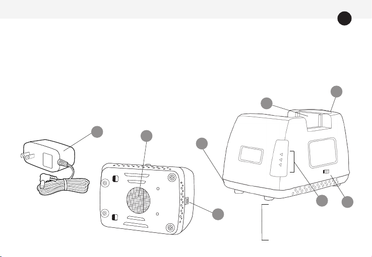
EC1C-BK2 Features
1. Metal charger base with
cooling fan vent (do not
cover).
2. Charging pod.
3. DC power connection – back
of charger.
4. Switch for selecting Calibration Mode or
Charge Only Mode.
5. Charge status LED – illuminates green,
red, or orange.
6. AC to DC power supply.
61
3
1
3
2
4
5
CHG - Charge Only Mode
CAL - Calibration Mode
PWR - Power On

5
Charging A Battery (Charge Only Mode)
1. Connect EC1C-BK2 to power with the power supply.
2. Set the switch on the side of the charger to Charge Only Mode (CHG).
3. Place the battery to be charged in the charging pod. The battery
may also be charged while attached to the radio. The radio may be
powered-on while in the charger when Charge Only Mode is selected.
4. When a battery is placed in the charging pod and while charging,
the CHG LED will illuminate RED with no ashing to indicate normal
charging.
5. If the CHG LED is red and ashes, a fault has been detected. The ash
pattern represents a specic fault condition. If the CHG LED is orange
and ashes, an advisement is being provided. See section Fault
Conditions & Advisements for details.
6. When the battery is charged to 80% of capacity, the CHG LED
will change to GREEN and begin to ash. It is recommended
that the battery be charged to at least 80% capacity before use.

6
Charging A Battery (continued)
7. The CHG LED will illuminate GREEN with no ashing when the battery
is fully charged.
8. After removing a fully charged battery, the CHG LED will illuminate
ORANGE for a few seconds. Allow the CHG LED to go off before placing
another battery in the charging pod.
9. The EC1C-BK2 is designed to charge batteries with a temperature
monitoring circuit when the battery temperature is between 0°C and
45°C (32° F – 113° F); batteries outside this temperature will not be
charged. When charging a battery, the ambient temperature should
be 5°C - 40°C (41° F - 104° F).

7
Calibrating A Battery (Calibration Mode)
1. Connect EC1C-BK2 to power with the power supply provided.
2. Set the switch on the side of the charger to Calibration Mode (CAL).
3. Place the battery to be calibrated in the charging pod. If the battery is
attached to the radio, keep the radio powered-off while calibrating.
4. The calibration process has three stages:
5. Assuming a battery is fully discharged when inserted, a 3600 mAh
battery will complete calibration in about 15 hours and a 2200 mAh
battery in about 9 hours. A battery that is only partially discharged
when inserted will complete calibration sooner.
First, the battery is charged. The CAL LED illuminates RED until
fully charged.
Second, the battery is discharged. The CAL LED illuminates
ORANGE until fully discharged.
Third, the battery is charged. The CAL LED illuminates RED
while charging, then illuminates GREEN to conrm calibration is
complete.

8
Calibrating A Battery (continued)
6. If the CAL LED ashes RED, a fault has been detected. If it ashes ORANGE,
you are receiving an advisement. The ash pattern indicates a specic
condition. See section Fault Conditions & Advisements for details.
7. If the battery is removed before calibration is completed, the calibration
process terminates. If the battery is then reinserted, the calibration
process commences with the rst stage.
8. If the mode selection switch is (accidently) changed from CAL to CHG
before calibration is completed, the calibration process continues
through the remaining stage(s) until calibration is completed. Removing
the battery and sliding the mode selection switch to CHG is required to
engage Charge Only Mode.
9. When calibrating a battery, the ambient temperature should be
5°C – 40°C (41°F – 104°F).

9
Fault Conditions & Advisements
When the charge status LED ashes RED, a fault condition exists. A fault
condition requires immediate attention. When the status LED ashes
ORANGE, you are receiving an advisement about the battery.
The ash patterns for fault conditions are as follows:
LED Pattern Fault Description
Flashes RED
1 Time
Indicates (A) low voltage battery failure or (B) battery has a short circuit. If
(A), the battery’s voltage is below the minimum level required and cannot be
charged. If (B), the battery is defective and should be recycled. This warning
is provided after the pre-charge stage is completed.
Flashes RED
2 Times
Indicates battery contact is “open” and current is not passing through the
(+) and (-) contacts on the battery. This warning is provided after the initial
diagnostic stage is complete.
Flashes RED
3 Times
Battery temperature is 45°C (113° F) or above. Charging has terminated,
remove battery from charger. Have battery checked by a qualied
technician.

10
Fault Conditions & Advisements (continued)
Solid ORANGE
(Battery removed.)
Brief reset period for charger after battery is removed. Allow the LED to go
off before inserting another battery.
Flashes ORANGE
/ GREEN
Battery temperature remains at 0°C (32° F) or below after two hours of
monitoring. Remove battery from charger and allow it to warm.
Flashes ORANGE
1 Time
Indicates battery is too cold when initially inserted. If the battery temperature is
0°C (32° F) or below, charging is delayed for up to two hours. Battery is monitored
and charging resumes once it is above freezing. Monitoring terminates if the
battery temperature remains below freezing for two hours.
Flashes ORANGE
2 Times
Indicates charging complete, but battery is under charged. Battery voltage
is below minimum level required. This warning is provided after the rapid
charging stage is complete.
LED Pattern Advisement

11
Replacing A Charging Pod
The charging pod is made from quality materials and designed to provide
years of service when properly used. Should replacement be necessary,
follow these steps:
1. Unplug EC1C-BK2 from its power source.
2. The charging pod is secured to the base with a single screw. To remove,
turn the locking screw on the bottom of the charging pod counter-
clockwise until it no longer holds the pod. Lift the charging pod from
the charging base.
3. Insert the replacement charging pod into the charger base and secure
with the locking screw. Do not over tighten the screw.
4. Inspect the charging contacts to ensure they are clean and
unobstructed.
5. Connect the power supply to the charger. You are now ready to charge
or calibrate your KNG radio battery.

12
Warranty And Service During Warranty
EC1C-BK2 is made from high quality materials and designed to provide years of reliable
service. The following warranty applies:
Power Products Unlimited, LLC (PPU) warrants this product to be free from defects in
workmanship and materials for two-years from date of purchase by the end user. This
warranty applies to the original purchaser and is void if the product has been altered, misused,
damaged, neglected, or if repair is required because of normal wear and tear. This is the
only warranty made by PPU. In no event will PPU, its afliates, subsidiaries, related entities,
or their respective directors, ofcers, or employees, be liable for any damages beyond
repair or replacement as described above, including without limitation, indirect, incidental,
or consequential damages. For service under warranty, return the product along with dated
proof of purchase to the retailer where purchased or to Power Products. If returning directly
to Power Products, follow these instructions:
• Send to Power Products – Warranty Service Department, 2170 Brandon Trail, Alpharetta,
GA 30004. For your protection, we recommend you obtain proof of delivery for your shipment.
• Include with your product, dated proof of purchase, your name and daytime telephone
number, and return address (street address only; return shipments cannot be made to a
P.O.Box).
• All items sent become the property of Power Products and will not be returned.

13
Specications subject to change without notice.
This device complies with Part 15 of the FCC Rules. Operation is subject to the following two conditions:
(1) this device may not cause harmful interference, and (2) this device must accept any interference
received, including interference that may cause undesired operation.
*Assumes fully discharged battery. Calibration times will be shorter for a partially discharged battery.
Specifications
Dimensions (W x L x H)
Weight
Compatible Chemistries
Ambient Operating Temperature
Power Supply (TWC1-PS)
Charger Input
Charge Rate
Calibration Time*
Approvals
96 x 131 x 87 mm / 3.8 x 5.2 x 3.3 inches
0.39 kg / 0.85 lbs. (charger only)
Li-Ion / LiPo
5° C - 40° C / 41° F - 104° F
Input 100V – 240V AC / 50 Hz – 60 Hz / 0.5A
15V DC / 1.0A (minimum)
800 mA (10.6V-13.5V)
15 hours (3600 mAh battery) / 9 hours (2200 mAh battery)
FCC / UL (power supply)
14
Part Number Description Information
TWC1-PS Power supply.
(Included with EC1C-BK2.)
UL listed. Input: 100-240V, 50-60Hz, 0.5A.
Output: 15.0V, 1.0A.
TWP-BK2 Charging pod.
(Included with EC1C-BK2.)
Includes fastening screw. For Li-Ion
batteries only.
EC1C-MB2 Desktop bracket for holding
two units.
Includes power supply for powering two
units.
Accessories


Endura Chargers By Power Products
Smart – Adaptable – Reliable™
2170 Brandon Trail • Alpharetta, GA 30004
www.powerproducts.com
©2020 Power Products Unlimited, LLC.
Power Products, Endura, and Smart-Adaptable-Reliable are trademarks of
Power Products Unlimited, LLC. All rights reserved.
Table of contents
Other Endura Batteries Charger manuals

Endura
Endura EVC User manual

Endura
Endura TWC6M User manual

Endura
Endura EC6M-V2 User manual

Endura
Endura EC-4173 User manual

Endura
Endura TWC12M User manual

Endura
Endura NCC0355 User manual

Endura
Endura NCC0325 User manual

Endura
Endura TWC1 User manual

Endura
Endura TWC6M User manual

Endura
Endura TWC1M User manual


