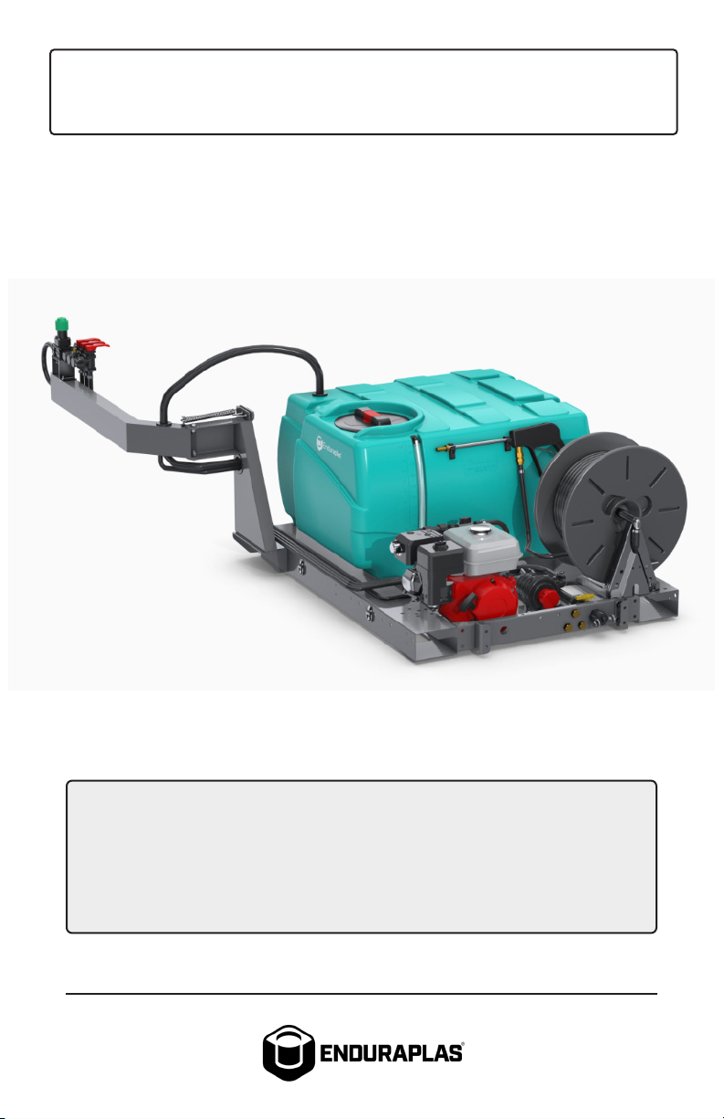
Enduraplas XSTREAM User manual

OWNER’S MANUAL
FIELD BOSS™
Version 2.0 Copyright © Enduraplas. All Rights Reserved.
Product Codes:
XSTREAM
SFB060FG290EX
SFB100FG290EX
SFB060FG290EX-ES
SFB100FG290EX-ES
365
SFB060FG225GH
SFB100FG225GH
SFB060FG225GH-ES
SFB100FG225GH-ES
ECOLITE
SFB060FG712V
SFB100FG712V
SFB060FG712V-ES
SFB100FG712V-ES

2Field Boss™
English
CONTENTS
INTRODUCTION 4
WARNINGS 5 & 6
CONNECTING THE RETENTION SPRING 7
INSTALLING DRING TIEDOWN SYSTEM 8
SETTING UP 365/XSTREAM PUMP 9
SETTING UP ECOLITE PUMP 10
SETTING UP SPRAYER 11 - 13
MOUNTING YOUR BOOM 14 - 16
MOUNTING 30’ BOOM EXTENSION 17
MOUNTING BOOMLESS NOZZLE 18
OPTIONAL ELECTRIC SOLENOID KIT 19 - 21
!

3Version 2.0
English
CONTENTS
CALIBRATING 22 & 23
MAINTAINING 24 & 25
CLEANING 26 & 27
WINTERIZING 28 & 29
TROUBLESHOOTING 30 & 31
WARRANTY 32 - 36
FIELD BOSS XSTREAM PARTS BREAK
DOWNS 37 - 54
FIELD BOSS 365 PARTS BREAKDOWNS 55 - 70
FIELD BOSS ECOLITE PARTS BREAK
DOWNS 71 - 82

4Field Boss™
English
INTRODUCTION
Congratulations! You now own an Enduraplas sprayer. Dura-
ble design and construction assure you a lifetime of extreme
performance. No sprayer is tougher. No sprayer will last lon-
ger.
Take a look through this owner’s manual to learn how the
pros use their Enduraplas sprayer.
Discover More Helpful Tips:
blog.enduraplas.com/spraying
Watch Instruction Videos:
www.youtube.com/enduraplas
Order Genuine Enduraplas Parts & Accessories:
parts.enduraplas.com

5Version 2.0
English
WARNINGS
1. When connecting this sprayer to your UTV (or vehicle),
ensure that you have read the UTV’s Owner’s Manual
and that you comply with all the weight restrictions as
specified by the UTV’s manufacturer, as overloading can
cause injury or death. Remember that 1 gallon of water
weighs 8.33 pounds.
2. To ensure your own safety and that of others, you must
comply with all relevant environmental, work place health,
safety legislation and codes of practice.
3. Select and wear appropriate Personal Protection
Equipment in accordance with the label of the product
you intend to use.
4. Care should be taken when spraying in windy conditions
as spray drift may contaminate the air and may aect the
operator or damage adjacent non-target vegetation. It is
recommended that a speed of 6mph is not exceeded.
5. Once the spraying operation has been completed,
decontaminate the spray tank and spray accessories.
Dispose of tank rinsing’s in compliance with current
environmental, work place health and safety regulations.
6. Personal Protection Equipment must still be worn while
decontaminating your sprayer as per warning 3 above.
7. Improper or careless use of this sprayer can cause serious
injury. Minors should never be allowed to use this sprayer.
This sprayer should not be used when bystanders or
animals are in the area. This sprayer should never be used
while children are in the area.
8. Never leave the sprayer unattended without turning o
the pump, relieving the line pressure, and flushing the
sprayer of any harmful chemicals.
9. You must be in good mental health to operate this sprayer
and not be under the influence of alcohol or any drugs
!

6Field Boss™
English
that could impair your vision, physical strength, dexterity,
judgment, or other mental capacity.
10. Be alert and never touch any part of the engine exhaust
system (muer, shield, header pipes, etc.) while the
engine is running. Always allow enough time, after
stopping the unit, for proper cooling of the muer and
surrounding parts.
11. Refuel engine with care. Gasoline is flammable, and
gasoline vapor can explode. Refuel in a well-ventilated
area, with the engine stopped.
12. Never run the pump in a closed or confined area. Exhaust
gas contains carbon monoxide which is poisonous to
humans. Avoid inhalation of exhaust gas.
13. No modifications and/or alterations may be made to this
sprayer. Any such modifications not only void the sprayer
warranty but can make the unit dangerous to anyone
operating the pump.
14. Always inspect hoses and piping to avoid burst injuries.
Discover More Helpful Tips:
blog.enduraplas.com/spraying
Watch Instruction Videos:
www.youtube.com/enduraplas
WARNINGS !

7Version 2.0
English
1) Loosely mount spring tension bracket
with provided two 1/4” x 2-1/2” bolts and
two 1/4” nylock nuts. Do not tighten bolts
at this point (hand tight). These need to
be loose for connecting retention spring
in step 2.
2) Hook the spring onto the hole in the
mounting plate and connect it to the bolt
on the control arm.
3) Tighten the bolts from step 1 on the
mounting plate using 1/2” wrench. This
will tension up the spring. With the spring
tensioned, it will hold the arm securely
in position whether folded in transport
position or in operating position.
Connecting the Retention Spring
SFB100FG290EX
GETTING STARTED

8Field Boss™
English
1) If you wish to use the d-ring tie-down
system, select your desired mounting
points on each side of the frame.
2) Install 2 d-ring tiedowns on each
side of the frame using the provided
d-rings and hardware. Tighten 1/4” bolts
(provided in bag) with 1/2” wrench. There
are multiple positions so the D-rings can
be mounted where best fits your UTV
bed.
SFB100FG290EX
Installing the D-ring Tie-down System
GETTING STARTED
Discover More Helpful Tips:
blog.enduraplas.com/spraying
Watch Instruction Videos:
www.youtube.com/enduraplas

9Version 2.0
English
Setting Up 365/Xstream Pump
SFB100FG290EX
GETTING STARTED
1) Fill the engine with regular gasoline.
2) Fill the engine oil reservor with 0.61
quarts of 10W - 30 engine oil or until oil is
to the top of fill plug.
3) The pump gear box on the Field Boss
XStream has already been filled with oil
so it will not need anymore. When pump
is cool, the oil will not show on dip stick;
oil will show on dip stick when pump
warms up. *FIELD BOSS®XSTREAM.

10 Field Boss™
English
SFB100FG290EX
Setting Up Ecolite Pump
GETTING STARTED
1) Connect the electrical cables to your
battery. Cable will need to be routed
safely to battery and hooked up red to
positive and black to negative.
2) Turn pump switch on. If the unit comes
with manual controls, the switch will be
on the control arm. If the unit comes with
electric in-cab controls, the switch will be
routed into the cab.

11Version 2.0
English
1) If you purchased the optional hand
wash tank, install the freshwater tank to
spray tank. Then, thread the spigot into
the opening on the fresh water tank. This
is used for fresh water to clean hands or
spills.
Setting Up Sprayer
3) Before starting your engine, make
sure the pressure regulator is fully open
(counterclockwise) to avoid premature
wear or damage to the pump. This will
allow liquid to flow from pump and return
back to tank. Pump should prime auto-
matically.
2) Fill tank 1/4 full with water. This is for
testing sprayer to make sure everything
is operating normal with no leaks before
filling with chemical.
GETTING STARTED
4) Start pump by switching the on/o
switch on motor to the on position and
pulling the rope. Choke accordingly with
the throttle half-way open.
*XSTREAM & 365 SPRAYERS ONLY.

12 Field Boss™
English
6) Once pump is running and liquid is
recirculating back into the tank, tighten
knob (clockwise) to desired pressure.
This will lessen the liquid flow from the
tank and redirect to the spray boom.
GETTING STARTED
Setting Up Sprayer
5) Turn on electric pump switch on con-
trol arm (pump should prime automatical-
ly). *ECOLITE SPRAYER ONLY.
7) Once you have set your desired pres-
sure, test the spray boom by turning on
Right, Center, and Left section controls.
When controls are in the up position,
the sprayer boom should be engaged. If
sprayer is equipped with electirc solem-
noids, refer to optional electric solenoid
kit.
8) When using hose reel, open valve in
hose reel feed line; this will allow the
liquid to flow into the hose reel. Picture
shown is XSTREAM sprayer.

13Version 2.0
English
Setting Up Sprayer
GETTING STARTED
9) When using the hose reel, make sure
the valve to the hose reel is open. This
will allow liquid to flow to the hose reel.
Picture shown is both 365 & ECOLITE.

14 Field Boss™
English
2) Install adjustable slide brackets to the
sprayer frame using hardware from step
1. Insert the 4 - 3/8” x 1” bolts through the
bracket and place plastic washers over
bolts to hold them in place.
3) Connect the adjustable slide brackets
by inserting the 3/8” x 1” bolts through
the C-bracket on sprayer frame and
install 3/8” washer and 3/8” lock nuts
loosely. By leaving nuts loose, it makes it
easier to do steps 5 & 6.
GETTING STARTED
Mounting Your Boom
1) The bag of hardware for mounting the
adjustable slide bracket to sprayer frame
includes:
4 - 3/8”x1” bolts
8 - 3/8” flat washers
4 - 3/8” self-retaining washers
4 - 3/8” nyloc nuts
4) The bag of hardware for mounting
the boom to the adjustable slide bracket
includes:
4 - 3/8” x 1” carriage bolts
4 - 3/8” flat washers
4 - 3/8” lock washers
4 - 3/8” hex nuts

15Version 2.0
English
6) When the boom is set to desired
height, tighten the hardware, making
sure the square neck on the carriage
bolt is fully inserted through the slot.
5) To install your boom to the adjustable
slide brackets, loosely install the carriage
bolts on the boom (leaving nuts and
washers on bolts). Align square head
of carriage bolts with adjustable slide
brackets and slide them into the brack-
et slots, then lower the boom down to
desired height.
Mounting Your Boom
7) Once the boom is secure, tighten the
hardware on the adjustable slide brack-
ets from step 3 to make sure they are
securely tightened.
GETTING STARTED

16 Field Boss™
English
8) Take the feed hoses from boom and
connect to male brass hose fittings on
spray unit. Hook hoses up to the appro-
priate section control; 12’, 20’ and 30’
booms have 3 hose hookups and boom-
less nozzle has 2 hose hookups. If hoses
are too long, they can be cut to desired
length.
9) Install bracket shown in picture to the
boom wing using supplied bolt. When
folding up the boom arms, remove the
clip pin and cradle the opposite wing
frame into bracket and reinsert clip pin
locking the booms in folded position.
Mounting Your Boom
GETTING STARTED

17Version 2.0
English
1) If you got the 30’ boom extensions,
once the 20’ boom is mounted to the
sprayer, bolt on the extensions to the
boom ends using the provided 5/16” X 2”
bolts.
2) Take the hose extension and screw
it to the existing brass fitting on the 20’
wing. Follow the same procedure for the
boom on the other side. Your 30’ exten-
sion is now plumbed to the 20’ boom.
GETTING STARTED
Mounting 30’ Boom Extension

18 Field Boss™
English
1) If you got the 30’ boomless nozzle kit,
bolt the boomless nozzle bracket to the
back of sprayer frame using provided
5/16” X 1” bolts.
2) Then, hook up hoses with female
brass fittings from boomless nozzle to
male brass ports on back of sprayer.
Make sure washer is intalled in female
fitting to prevent leaking.
Please refer to the spray boom owner’s manual for boom
assembly and parts breakdown.
GETTING STARTED
Mounting Boomless Nozzle

19Version 2.0
English
Optional Electric Solenoid Kit
1) If you ordered your sprayer with the
optional electric solenoid controls, mount
contoller in cab; make sure this is mount-
ed where it will not obstruct operators
view.
2) Connect the wire harness from the
controller to the 3 electric valve banks
on sprayer by plugging in the matching
ends to the valves. Blue is on the left,
brown is in the center, and black is on
the right.
4) Connect white pressure line from con-
troller to valve bank with provided con-
nectors. Make sure white pressure hose
is bottomed out all the way into connec-
tor fittings before tightening connector.
The in-cab controller guage will then
show the pressure at the valve bank.
GETTING STARTED
3) There are 2 wires in this harness
running back to the solenoid kit that plug
into the electric valve, yellow is positive
and green is negative.

20 Field Boss™
English
6) Turn on vehicle key to power up
controller and turn on master switch on
controller. This will power up electric
solenoid bank on sprayer.
8) Fill tank 1/4 full with water. This is
so you can test the unit running liquid
through the system without damaging
pump.
7) To make sure your solenoids have
power, switch the 3 valve controls on and
o listening for the valves to click open
and shut on the sprayer. This will ensure
valves are powered and operating.
5) This unit comes with power wires that
you will either need to add gator clips
to or wire directly to a power source. If
gator clips are used, connect to battery;
red to positive and black to negative.
Make sure wire is routed where there is
no place for it to get cut or pinched.
GETTING STARTED
Optional Electric Solenoid Kit
This manual suits for next models
14
Table of contents
Other Enduraplas Paint Sprayer manuals

Enduraplas
Enduraplas ICEMASTER LIQUID MASTER T Series User manual

Enduraplas
Enduraplas Gold Series User manual

Enduraplas
Enduraplas FIELD BOSS 365 SFB060FG225GH User manual

Enduraplas
Enduraplas SPOT CHIEF SSC025212V User manual

Enduraplas
Enduraplas FIELD BOSS ECOLITE SFB060FG712V User manual

Enduraplas
Enduraplas CLEAN BOSS PRO User manual

Enduraplas
Enduraplas IceMaster Systems Liquid Master W Series User manual

Enduraplas
Enduraplas STEEL BOOM User manual