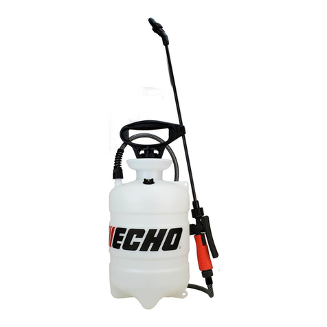
Enduraplas IceMaster Systems Liquid Master W Series User manual

LIQUID MASTER W-SERIES
®
OWNER’S MANUAL
Version 1.1 Copyright © Enduraplas. All Rights Reserved.
Product Codes:
IMS12W24V

2Liquid Master® W-Series
English
CONTENTS
INTRODUCTION 3
WARNINGS 4 - 7
SETUP & DRAWINGS 8 - 17
MAINTAINING 18 - 19
TROUBLESHOOTING 20 - 21
!

3Version 1.1
English
INTRODUCTION
Congratulations! You now own an ICE MASTER SYSTEMS
sprayer. Durable design and construction assure you a
lifetime of extreme performance. No sprayer is tougher. No
sprayer will last longer.
Take a look through this owner’s manual to learn how the
pros use their ICE MASTER SYSTEMS sprayer.
Discover More Helpful Tips:
blog.enduraplas.com/ice-control
Watch Instruction Videos:
www.youtube.com
Search ‘ICE MASTER SYSTEMS’

4Liquid Master® W-Series
English
WARNINGS
1. Do not exceed vehicle manufacturers loading, towing or
lifting specications and regulations.
2. Ensure tank is rmly secured in an appropriate manner.
3. Use caution at all times, particularly when driving on
rough terrain.
4. Comply with chemical manufacturers safety requirements
and all relevant legislations.
5. ALWAYS keep tank tightly covered, to prevent children or
animals from entering tank.
6. Tank is not re resistant. NEVER expose it to open ame
or heat.
7. Keep sharp objects from tank. Tank could be punctured
and contents could escape and cause injury to persons
or property.
8. This tank can be used only with polyethylene compatible
liquids. If you are uncertain, ask chemical supplier if
material can safely be stored in a polyethylene tank.
USE OF TANK WITH ANY OTHER MATERIAL COULD
CAUSE TANK TO FAIL, RESULTING IN INJURY OR
PROPERTY DAMAGE.
9. DO NOT MIX CHEMICALS. THIS CAN RESULT IN
DAMAGE TO THE TANK OR NEARBY PERSONS OR
PROPERTY.
10.Clean out tank before changing chemicals OTHERWISE
A DANGEROUS MIXTURE OF CHEMICALS
COULD CAUSE DAMAGE TO PERSONS, TANK OR
PROPERTY.
11. Regular service and maintenance is the Owner’s
responsibility and is a condition of your warranty.
12.FAILURE TO COMPLY WITH ALL WARNINGS
AND INSTALLATION INSTRUCTIONS WILL VOID
WARRANTY.
!

5Version 1.1
English
Discover More Helpful Tips:
blog.enduraplas.com/ice-control
Calcium Chloride Brine, Salt Brine and Premium Branded
Liquids.
Caution: Brine that contain tacky substances or solid
particles may clog pumps and nozzles. These are not
recommended.
Warning: DO NOT USE any products that contain
petroleum or petroleum by-products of any kind. These
destroy seals and will void warranty.
COMPATIBLE LIQUIDS
!
!
13.No modications and/or alterations may be made to this
sprayer. Any such modications not only void the sprayer
warranty but can make the unit dangerous to anyone
operating the pump.
14.Always inspect hoses and piping to avoid burst injuries.
15.DO NOT turn suction valve o while pump is running.
NEVER RUN PUMP DRY.

6Liquid Master® W-Series
English
WARNING
WARNING: Improper use or failure to follow instructions can result in explosive failure causing serious
eye or other injury. For safe use of this product you must read and follow all instructions. Do not leave a
pressurized sprayer in the hot sun. Heat
can cause pressure build-
up resulting in possible explosion. Do not
store or leave solution in tank after use. Always wear goggles,
gloves,
long sleeve shirt, long pants and full foot
protection when spraying. Do not attempt to modify this sprayer. Replace parts only with manufacturer’s original
parts. Never spray flammable, caustic, acidic, chlorine, bleach or other corrosive solutions or heat,
pressure, or gas producing chemicals. Always read and follow chemical manufacturer’s instructions
before use with
this sprayer as some chemicals may be hazardous when used with this sprayer.
CAUTION
•
PRE-USE CHECK: Before each use check tightness of hose nut to be sure hose is securely attached to
the shut-off assembly. Ensure that all nozzle and wand connections are tight.
•
Do Not exceed a tank solution temperature of 120º F/ 49º C.
NOTE: The tank and hose may have residual water in it due to quality testing performed on the sprayer.
WARNING
This sprayer is designed to operate with a Chapin 24V Lithium Ion battery ONLY. Any other batteries could
cause serious harm or injury to the operator and serious damage to the sprayer.
WARNING: For safe operation, read this manual before using the charger
. The battery pack is not fully charged
out of the carton. Before using the battery pack and charger, read the safety instructions below. Then follow
charging procedures outlined.
NOTE: Remove battery and place in charger when not in use.
IMPORTANT SAFETY INSTRUCTION FOR BATTERY PACKS READ ALL
INSTRUCTIONS
•DO NOT incinerate the battery pack even if it is severely damaged or is completely worn out. The
battery pack can explode in a fire. Toxic fumes and materials are created when battery packs are burned.
•
DO NOT charge or use battery in explosive atmospheres, such as in the presence of flammable
liquids, gases or dust.
Inserting or removing the battery from the charger may ignite the dust or fumes.
•If battery contents come into contact with the skin, immediately wash area with mild soap and water.
If battery liquid gets into the eye, rinse water over the open eye for 15 minutes or until irritation ceases. If
medical attention is needed, the battery electrolyte for Lithium-Ion batteries is composed of a mixture of
liquid organic carbonates and lithium salts.
•
Contents of opened battery cells may cause respiratory irritation. Provide fresh air. If symptoms persist,
seek medical attention.
WARNING: Burn hazard. Battery liquid may be flammable if exposed to spark or flame.
•
Charge the battery packs only in Chapin chargers.
•
DO NOT splash or immerse in water or other liquids. This may cause premature cell failure.
•DO NOT store or use the tool and battery pack in locations where the temperature may reach or
exceed 105ºF (40ºC) (such as outside sheds or metal buildings in summer).
WARNING:
Never attempt to open the battery pack for any reason. If battery pack case is
cracked or damaged,
do not insert into charger.
Do not crush, drop or damage battery pack. Do not use a battery pack or charger
that
has
received a sharp blow, been
dropped, run over or damaged in any way (i.e., pierced with a nail, hit with a
hammer,
stepped on). Damaged battery packs should be returned to service center for recycling.
WARNING:
Fire hazard. Do not store or carry battery so that metal objects can contact exposed
battery
terminals.
For example, do not place battery in aprons, pockets, tool boxes, product kit boxes, drawers,
etc.,
with
loose nails, screws, keys, etc.
Transporting
batteries can possibly cause fires if the battery terminals inadvertently come in contact
with
conductive
materials such as keys, coins, hand tools and the like.
The US Department of transportation
Hazardous Material Regulations (HMR) actually prohibit transporting batteries in commerce or on airplanes (i.e.,
packed in suitcases and carry-on luggage) UNLESS they are properly protected from short circuits. So when
transporting individual batteries, make sure that the battery terminals are protected and well insulated from
materials that could contact them and cause a short circuit.NOTE: Lithium-Ion batteries should not be put in
checked baggage.

7Version 1.1
English
STORAGE RECOMMENDATIONS
1.The best storage place is one that is cool and dry away from direct sunlight and
excess heat or cold.
2.Long storage will not harm the battery pack or charger.
CHARGING PROCEDURE
Chapin chargers are designed to charge Chapin battery packs in 3.5-4 hours
depending on the pack being charged.
1.Plug the charger (C-13) into an appropriate outlet before inserting the battery pack.
2.Insert the battery pack (C-12) into the charger as shown in figure A.
3.The red light on the charger is continuously on when the battery is charging.
C-13
Figure
A
4.The green light on the charger is continuously on when the battery is charged. The pack is fully charged and
may be used at this time
or left on the charger.
5.Blinking red and green lights on the charger indicates a defective battery and should properly be disposed of.
Battery Charge Indicator
When battery is disconnected from the charger,
depress green button to see the charge level.
To charge see “Charging Pocedures” in this
manual.
Recharge discharged batteries as soon as
possible
after use or battery life may be
greatly diminished. For longest b
attery life, do
not discharge batteries fully. It
is
recommended that the batteries be recharged
after each use.
LEAVING THE BATTERY IN THE CHARGER
Red Needs
Charge
1/4 Charge
1/2 Charge
3/4 Charge
Green Check Button
The charger and battery pack can be left connected with the green LED
glowing indefinitely.
The charger will keep the battery pack fresh and fully charged.
IMPORTANT CHARGING NOTES
1. Longest life and best performance can be obtained if the battery pack is charged when the air temperature is
between 65°F and 75°F (18°- 24°C). DO NOT charge the battery pack in an air temperature below +40°F
(+4.5°C), or above +105°F (+40.5°C). This is important and will prevent serious damage to the battery pack.
2.The charger and battery pack may become warm to touch while charging. This is a normal condition, and does
not indicate a problem. To facilitate the cooling of the battery pack after use, avoid placing the charger or battery
pack in a warm environment such as in a metal shed, or an uninsulated trailer.
3.If the battery pack does not charge properly:
a.Check current at receptacle by plugging in alamp or other appliance.
b.Check to see if receptacle is connected to alight switch which turns power off when you turn out the lights.
c.Move charger and battery pack to a location where the surrounding air temperature is approximately 65°F and
75°F (18°- 24°C).
4.
The battery pack should be recharged when it fails to produce sufficient power on jobs which were easily
done previously. DO NOT CONTINUE to use under these conditions. Follow the charging procedure. You may
also charge a partially used pack whenever you desire with no adverse affect on the battery pack.
5.Foreign materials of a conductive nature such as, but not limited to, steel wool, aluminum foil, or any buildup of
metallic particles should be kept away from charger cavities. Always unplug the charger from the power supply
when there is no battery pack in the cavity. Unplug charger before attempting to clean.
6.Do not freeze or immerse charger in water or any other liquid.
WARNING: Shock hazard. Do not allow any liquid to get inside charger. Never attempt to open the battery pack for
any reason. If the plastic housing of the battery pack breaks or cracks, call 1-800-822-8837 for recycling
information.
C-12

8Liquid Master® W-Series
English
INSTALLING AND REMOVING THE BATTERY PACK
FROM THE SPRAYER
WARNING: Make sure switch is in the off position.
TO INSTALL BATTERY PACK:
Insert battery pack into tool until an
audible click is heard (Figure B). Make sure battery pack is fully
seated and latched into position.
TO REMOVE THE BATTERY PACK: Depress the battery release
button as shown in Figure C and pull battery pack out of tool.
Figure
C
IMPORTANT SAFETY INSTRUCTIONS FOR BATTERY CHARGERS
Figure
B
SAVE THESE INSTRUCTIONS:
This manual contains important safety instructions for battery chargers.
•
Before using charger, readall instructions and cautionary markings on charger,battery pack, and product usingbattery pack.
WARNING: Shock hazard.
Do not allow any liquid to get inside charger.
CAUTION: Burn hazard.
To reduce the risk of injury, charge only designated Chapin batteries. Other types of batteries my burst
causing
personal injury and damage.
CAUTION:
Under certain conditions,with the charger plugged into the power supply,the charger canbe shorted by foreign material.
Foreign
materials of aconductive nature such as, but not limited to, steel wool, aluminum foil, or any build up of metalic partices should be
kept
away from charger cavities.Always unplug the charger from the power supply when there is no battery pack in the cavity. Unlplug
charger
before attempting to clean.
WARNING:
DO NOT attempt to charge the battery pack with any chargers other than the ones in this manual.
The charger and
battery
pack are specifically designed to work together.
•
ThesechargersarenotintendedforanyusesotherthanchargingdesignatedChapin rechargeablebatteries.
Anyotherusesmay
result in risk of fire, electric shock or electrocution.
•
DO NOT expose charger to rain or snow.
•
Pullby plugratherthan cord whendisconnectingcharger.
This will reducerisk ofdamageto electricplugandcord.
•
Makesurethat cord islocatedso that itwillnotbesteppedon,trippedover,orotherwise subjected todamageorstress.
•
DO NOT use an extension cord unless it is absolutely necessary.
Use of improper extension cord could result in risk of fire,
electric
shock, or electrocution.
•
An extension cord must have adequate wire size (AWG or American Wire Gauge) for safety.
The smaller the gauge number of the
wire, the greater the capacity of the cable, that is 16 gauge has more capacity than 18 gauge. When using more than one extension to
make up the total length, be sure each idividual extension contains at least the minimum wire size.
•
DO NOT operate charger with damaged cord or plug
-have them replaced immediately.
•
DO NOT operate charger if it has received asharp blow, been dropped, or otherwise damaged in any way.
Take it to an
authorized
service center.
•
DO NOT dissassemble charger;
take it to an authorized service center when service or repair is required. Incorrect reassembly may
result in a risk of electric shock electrocution or fire.
•
Disconnect the charger from the outlet before attempting any cleaning.
This will reduce the risk of electric shock. Removing the
battery pack will not reduce the risk.
•
NEVER attempt to connect 2chargers together.
•
The charger is designed to operate on standard household electrical power (120Volts). Do not attempt to use it on any other
voltage.
Symbols The label on your tool may include the following symbols.
Vvolts Hz
hertz
min minutes
direct current
Class I Construction
(grounded)
Class II Construction
( double insulated)
Read instruction
manual before use
Use proper eye
protection
Aamperes
W watts
alternating current
no load speed
earthing terminal
safety alert
symbol
/min or
rpm
revolutions
or
reciprocation per minute
Use proper
respiratory protection
Use proper hearing
protection

9Version 1.1
English
Sprayer Hardware
(Actual size)
H-3
H-1
H-2
H-5
H-4
H-6
H-7(X2)
H-8
H-9 (X2)
H-10
H-12,(X2)
H-11 (X2)
Contents:

10 Liquid Master® W-Series
English
TOOLS NEEDED:
10 mm
10 mm
Sprayer Components
(Not Actual size)
C-1
Wheels
C-3
Axel Rod
C-6
Nozzle Bar
C-5
Handle Bar Tubing
C-2
Tank
C-4
On/off Switch Wiring Harness
(Attached to C-2)
C-7
Nozzle Bracket
C-11
Handle
C-12
Battery
C-10
Handle
C-8
Frame Leg
C-9
Frame Leg
C-13
Battery
Charger
C-16
Tank Filter Basket
C-17
Tank Cap
C-14
Extension Wand
C-15
Discharge w/hose
Note: Not all components shown may be needed on your model

11Version 1.1
English
FRAME LEG INSTALLATION
Attach frame leg (C-8 and C-9) with nuts and bolts (H-1) to tank assembly (C-2). Install end caps (H-12) into
frame legs (C-8 and C-9).
C-8
H-1
H-1
H-1
C-9
H-1
H-12
H-12
H-1
H-1
H-1
H-1
C-4
HANDLEBAR INSTALLATION
Run on/off switch wiring harness (C-4) through handlebar
tubing (C-5).
Bolt handle bar to assembled frame legs using H-1 nuts
and bolts.
H-1
H-1
H-1
H-1
C-5
C-4

12 Liquid Master® W-Series
English
H-1
H-9
H-1
H-1
C-5
H-9
H-1
C-4
C-17
C-16
ASSEMBLE FILTER AND CAP
Insert Filter (C-16) and twist on cap (C-17).
Bolt wand clips (H-9) to handlebar tube (C-5).

13Version 1.1
English
Connect the on/off wiring harness ( C-4) to switch and insert switch bracket (H-10) into square handle bar tubing
(C-5). Bolt the right (C-10)
and left handles (C-11) to the handle bar tubing using (H-1) bolts. Lastly, insert handle grips (H-11) onto
handlebars (C-10 and C-11).
H-11
C-11
H-10
H-10
C-10
H-1
H-1
H-11
H-1
H-1
C-5
C-4
Flip unit upside down for easy access.
Insert axel rod (C-3) into axel bracket
until centered; then fasten each wheel
with washer (H-7) and cotter pin (H-3)
using the outermost hole in axel. Bend
each cotter pin to ensure asecure
installation.
H-7
H-3
Ben
d
Cotter Pin
attaches on
outside of each
wheel
C-1
C-1
H-7
H-7
C-3
C-3
H-3
H-3
AXEL AND WHEEL INSTALLATION
ASSEMBLE HANDLES AND ON/OFF SWITCH

14 Liquid Master® W-Series
English
ASSEMBLE ADJUSTABLE NOZZLE BRACKET
Assemble cam lock bracket (H-4) with supplied nuts and bolts from (H-4) to nozzle bracket (C-7). Then
fasten nozzle assy (H-2) to
nozzle bar (C-6) as shown.
C-6
H-4
C-6
H-4
C-7
H-4
H-4
C-7
H-2
H-2
Assembl
ed
Using supplied machine screws (H-6) fasten adjustable nozzle bracket assembly to tank.Assemble hose from tank
(C-2) to nozzle assembly
(H-2) with worm gear clamp (H-5).
H-5
H-2
H-6
H-6
Assembl
ed
ATTACH NOZZLE BRACKET AND ADJUSTABLE NOZZLE TO TANK

15Version 1.1
English
ASSEMBLE DISCHARGE TO DIVERTING
VALVE
Connect discharge with hose (C-15) to diverting valve as shown. Thread hose through loop clamp (H-8)( Figure A).
Assemble worm gear clamp
(H-5) to hose (Figure B). Assemble hose to diverting valve (Figure C). Tighten worm gear clamp and loop
clamp.
H-8
Figure A
H-5
H-8
C-15
BB
Figure B
Image shown without
frame legs and handle
bar for clarity
Figure C
ASSEMBLE WAND TO SHUT-OFF
Make sure the O-ring is installed on the end of the extension wand (C-14). Insert the wand into discharge with
hose (C-15). Turn and
tighten the retaining nut clockwise onto the shut-off valve.
O-ring
Retaining Nut
Discharge with Hose (C-15)
Wand (C-14)

16 Liquid Master® W-Series
English
FILLING THE SPRAYER
Make sure the filter basket is in place to keep debris from entering the tank.
Determine the amount of mixture needed for your application. Add the proper amount of water to the tank. Add the proper
amount of chemical to the tank (check the chemical label for proper ratio of chemical). Stir mixture in tank with a clean
utensil (like a paint stirrer). The tank will hold
the 12-gallon (45.4L) capacity plus the chemical.
It is not necessary to completely fill the sprayer tank with each use.
You can fill the tank with only the amount
needed for each application. Always follow the manufacturer’s instructions included on their product la
bel.
OPERATING THE SPRAYER
•
Plug in charged battery
•
Turn switch to on position
•Spray liquid back into tank to prime
pump
•
Close shut-off. Pump should stop
running.
•Replace cap & begin spraying.
When finished spraying turn switch to off position. Remove and re-charge battery.
Note: Unit is equipped with a battery protection circuit. If sprayer abruptly stops after spraying for an extended period
of time, the battery may require charging.
POWDER-BASED CHEMICALS
Powder
-based chemicals (powder mixed with liquids to make the spraying agent) are usually abrasive and can cause
wear.
When you use a powder-based chemical in your sprayer, make sure it is thoroughly dissolved in the liquid
solution.
Thoroughly clean and flush the sprayer with water to extend the life of the sprayers parts.
CLEANING
•Always empty the sprayer and clean the tank thoroughly after each use.
Other Cleaning Tips:
•Improper spray distribution usually means the nozzle is clogged, remove the nozzle and clean it.
•Soap can be added to the water to clean the tank.
•Do not use strong cleaning agents or abrasives.
•If you use a chemical agent to clean the tank follow the manufacturer’s recommendations for the
disposal of the waste water.
•Follow the chemical manufacturers instructions for clean-up.
STORING / MAINTAINING YOUR SPRAYER
The Battery Should be removed prior to storage.
•The sprayer should be stored out of direct sunlight in a cool dry space.
•Before freezing weather make sure to drain all liquid in the tank, pump, hose, shut-off valve, wand and nozzle,to
avoid liquid expansion and cracking in the sprayer components (See “Cleaning” section). Lock the shut-off valve in
the “open” position.
•When service is required call your nearest dealer and always insist on original manufactured replacement parts.
•Inspect the hose, wand, tank and shut-off valve for wear, damage or leaks on a regular basis and repair defects
promptly.
Recycling Spent Battery
In some areas, it is illegal to place spent lithium-ion batteries in the trash or municipal solid waste stream. You may
also contact your local recycling center for information on where to drop off the spent battery, or call 1-800-8-
BATTERY.

17Version 1.1
English
SWITCH FROM BOOM SPRAY TO SPOT
SPRAY
Turn switch to the desired spray
option.
SPRAY PATTERN ADJUSTMENT FOR PUSH
SPRAYING
Easily spray to left or right with positionable wand holder built right
into the cap.
Spray Right
Spray left
ADJUST NOZZLE HEIGHT
Loosen the cam lock handle to adjust the
height
of the nozzle bar.

18 Liquid Master® W-Series
English
MAINTAINING
Keeping your sprayer in good condition will help you
lengthen the life of the sprayer. Everyone knows a well
maintained piece of equipment ensures a longer life span.
Sprayer maintenance can seem a huge task if you don’t
have the right tools.
Discover More Helpful Tips:
blog.enduraplas.com/ice-control
Watch Instruction Videos:
www.youtube.com
Search ‘ICE MASTER SYSTEMS’
FILLING THE SPRAYER
Make sure the filter basket is in place to keep debris from entering the tank.
Determine the amount of mixture needed for your application. Add the proper amount of water to the tank. Add the proper
amount of chemical to the tank (check the chemical label for proper ratio of chemical). Stir mixture in tank with a clean
utensil (like a paint stirrer). The tank will hold the 12-gallon (45.4L) capacity plus the chemical.
It is not necessary to completely fill the sprayer tank with each use. You can fill the tank with only the amount
needed for each application. Always follow the manufacturer’s instructions included on their product label.
OPERATING THE SPRAYER
•Plug in charged battery
•Turn switch to on position
•Spray liquid back into tank to prime
pump
•Close shut-off. Pump should stop
running.
•Replace cap & begin spraying.
When finished spraying turn switch to off position. Remove and re-charge battery.
Note: Unit is equipped with a battery protection circuit. If sprayer abruptly stops after spraying for an extended period
of time, the battery may require charging.
POWDER-BASED CHEMICALS
Powder-based chemicals (powder mixed with liquids to make the spraying agent) are usually abrasive and can cause
wear. When you use a powder-based chemical in your sprayer, make sure it is thoroughly dissolved in the liquid
solution. Thoroughly clean and flush the sprayer with water to extend the life of the sprayers parts.
CLEANING
•
Always empty the sprayer and clean the tank thoroughly after each use.
Other Cleaning Tips
:
•
Improper spray distribution usually means the nozzle is clogged, remove the nozzle and clean it.
•
Soap can be added to the water to clean the tank.
•
Do not use strong cleaning agents or abrasives.
•
If you use a chemical agent to clean the tank follow the manufacturer’s recommendations for the
disposal of the waste water.
•
Follow the chemical manufacturers instructions for clean-up.
STORING / MAINTAINING YOUR SPRAYER
The Battery Should be removed prior to storage.
•
The sprayer should be stored out of direct sunlight in a cool dry space.
•
Before freezing weather make sure to drain all liquid in the tank, pump, hose, shut-off valve, wand and nozzle,to
avoid liquid expansion and cracking in the sprayer components (See “Cleaning” section). Lock the shut-off valve in
the “open” position.
•
When service is required call your nearest dealer and always insist on original manufactured replacement parts.
•Inspect the hose, wand, tank and shut-off valve for wear, damage or leaks on a regular basis and repair defects
promptly.
Recycling Spent Battery
In some areas, it is illegal to place spent lithium
-ion batteries in the trash or municipal solid waste stream. You may
also contact your
local recycling center for information on where to drop off the spent battery, or call 1-800-8-
BATTERY.

19Version 1.1
English
The information applies in normal operating conditions. The specic intervals must be short-
ened accordingly for longer daily working hours. If the machine is only used occasionally, the
intervals can be extended accordingly.
Before starting work
At the end of work
and/or daily
Weekly or every 40
operating hours
After the rst 5
operating hours
Every 250 operating
hours o once a year
If damaged
If required
Complete machine
Visual inspection (condition, leaks) X
Clean
Tank, hoses and ttings
Clean X
Drain X
In-line lter Clean X X
Spray lance nozzle
Clean X
Replace X
All accessible screws and nuts Retighten X
Safety labels Replace X
Pump Maintain Read and follow all maintenance and care instructions in the
Pump manual.

20 Liquid Master® W-Series
English
TROUBLESHOOTING
CONDITION CAUSE REMEDY
Pump will not
prime
1) Insucient motor
RPM
2) Air leak on suction
plumbing
3) Blocked/Restricted
intake hose
4) Filter cap
disengaged
5) Filter gasket
damaged/missing
1) Increase motor
RPM until pump
primes
2) Tighten/replace
ttings & hose
clamps. Verify suction
hoses are in good
condition
3) Remove blockage
from suction line,
ensure line is not
kinked
4) Lock lter cap into
position
5) Replace lter
gasket
Pressure drops/
uctuates during
standard
operation
1) Restriction on
suction line
2) Pump sucking air
3) Plugged lter
4) Damaged regulator
1) Inspect tank and
suction lines and
remove restriction
2) Tighten ttings
3) Remove and
clean lter mesh and
housing
4) Remove regulator
stem and inspect for
broken parts/pieces
This manual suits for next models
1
Table of contents
Other Enduraplas Paint Sprayer manuals

Enduraplas
Enduraplas STEEL BOOM User manual
Enduraplas
Enduraplas FIELD BOSS 365 SFB060FG225GH User manual
Enduraplas
Enduraplas SPOT CHIEF SSC025212V User manual
Enduraplas
Enduraplas FIELD BOSS ECOLITE SFB060FG712V User manual

Enduraplas
Enduraplas ICEMASTER LIQUID MASTER T Series User manual
Enduraplas
Enduraplas XSTREAM User manual
Enduraplas
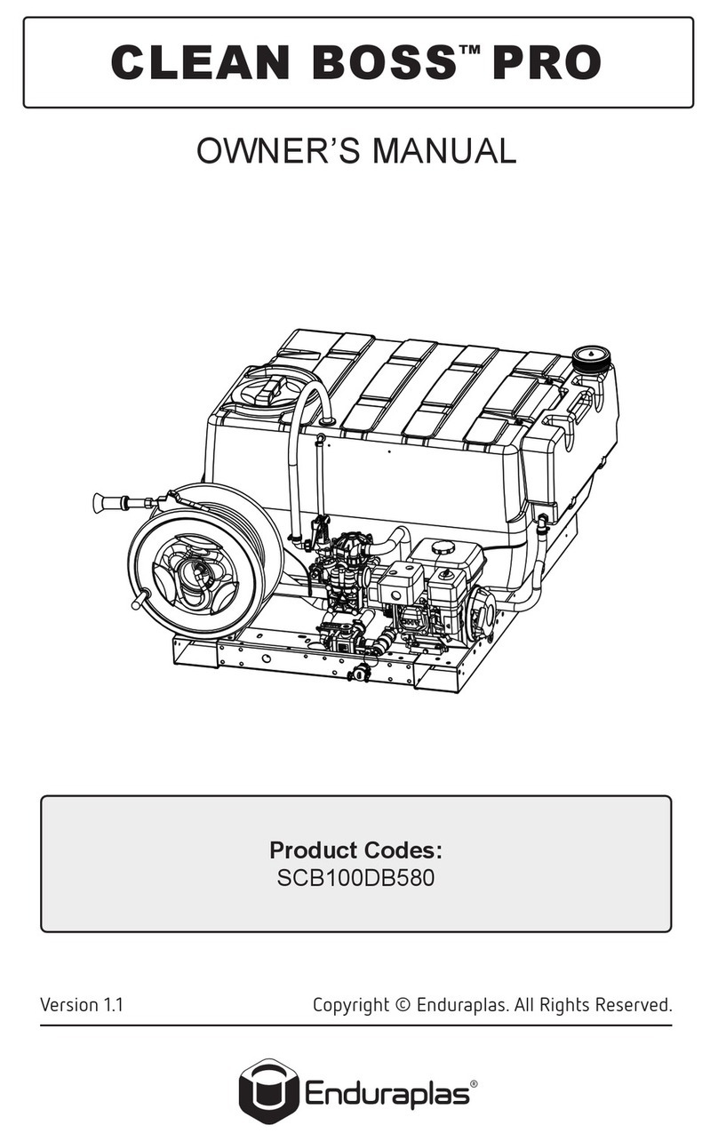
Enduraplas CLEAN BOSS PRO User manual

Enduraplas
Enduraplas Gold Series User manual
