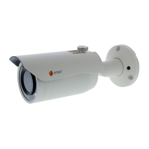
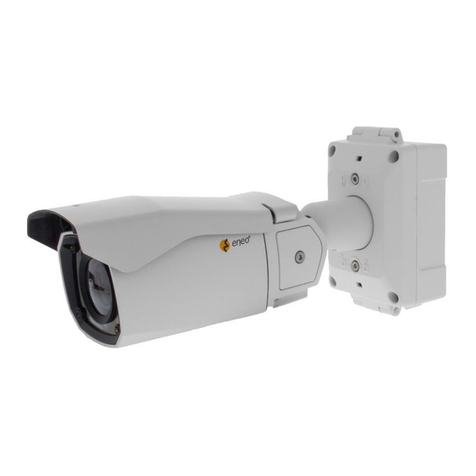
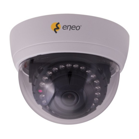
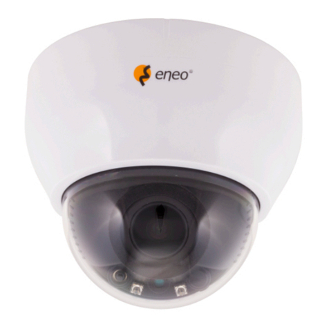
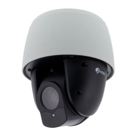
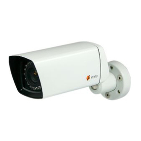
Eneo MEB-55M2812M0A User manual

EN
User Manual
1/2.8" HD Camera / HD Dome,
Day&Night, 2592x1944, Infrared
2,7-13,5mm, 12VDC, IP67
MEB-55M2812M0A
MED-65M2812M0A

1
REGULATORY INFORMATION
FCC COMPLIANCE STATEMENT
FCC Conditions
This device complies with Part 15 of the FCC Rules. Operation is subject to the following
two conditions: (1) this device may not cause harmful interference, and (2) this device must
accept any interference received, including interference that may cause undesired operation.
FCC Compliance
This equipment has been tested and found to comply with the limits for a Class
A digital device, pursuant to Part 15 of the FCC Rules. These limits are designed to
provide reasonable protection against harmful interference when the equipment is operated in a
commercial environment. This equipment generates, uses, and can radiate radio frequency
energy and, if not installed and used in accordance with the instruction manual,
may cause harmful interference to radio communications. Operation of this equipment in a
residential area is likely to cause harmful interference in which case the user will be required to
correct the interference at its own expense.
FCC Information
Please pay attention that changes or modification not expressly approved by the party
responsible for compliance could void the user’s authority to operate the device.
EU CONFORMITY STATEMENT
This product and –if applicable –the supplied accessories too are marked with
“CE”and comply therefore with the applicable harmonized European standards
listed under the Low Voltage Directive 2014/35/EU, the EMC Directive 2014/30/EU,
Radio Equipment Directive 2014/53/EU and the RoHS Directive 2011/65/EU
2012/19/EU (WEEE directive): Products marked with this symbol cannot be
disposed of as unsorted municipal waste in the European Union. To prevent
possible harm to the environment or human health from uncontrolled waste
disposal, please separate this from other types of wastes and recycle it responsibly
to promote the sustainable reuse of material resources.
Household user should contact either the retailer where they purchased this product, or their
local government office, for details of where and how they can take this item for
environmentally safe recycling.
Business users should contact their supplier and check the terms and conditions of the
purchase contract. This product should not be mixed with other commercial wastes for
disposal.
INDUSTRY CANADA ICES-003 COMPLIANCE
This device meets the CAN ICES-3 (A) / NMB-3 (A) standard requirements.

2
SAFETY INSTRUCTIONS
These instructions are intended to ensure that users can use the product correctly to avoid any
danger or property loss.
Warnings: Serious injury or death may happen if any of the warnings are ignored.
Cautions: Injury or equipment damage may happen if any of the cautions are ignored.
Warnings: Follow these instructions to
prevent serious injury or even death.
Cautions: Follow these precautions to avoid
any potential injury or material damage.
Warnings
In the use of the device, you must be in strict compliance with the electrical safety regulations of the
nation and region.
Input voltage should meet both the SELV (Safety Extra Low Voltage) and the limited Power Source
with 12 VDC according to the IEC60950-1 standard. Refer to technical specifications for details.
To reduce the risk of fire or electric shock, do not expose this product to rain or moisture environment.
Un-plug this apparatus during lightning storms or when unused for long periods of time.
Do not connect multiple devices to one power adaptor to avoid over-heating or a fire hazard caused
by overload.
If smoke, odor or noise rise from the device, please immediately turn off the power and unplug the
power cord, and then contact us.
Don’t disassemble the device by one unprofessional person. These servicing instructions are for use
by qualified service personnel only. To reduce the risk of electric shock. Do not perform any
servicing other than that contained in the operating instructions unless you are qualified to do so.
Do not block any ventilation openings. To avoid heat accumulation, good ventilation is required for
the operating environment. Install in accordance with the manufacturer’s instructions.
Cautions
Do not drop the camera or subject it to physical shock
Protect the power cord from being walked on or pinched particularly at plugs, convenience
receptacles, and the point where they exit from the apparatus.
Do not touch sensor modules with fingers.
Do not install near any extremely heat sources such as radiators, heat registers, stoves, or other
apparatus (including amplifiers) that produce heat. Also do not place the camera in cold (its
operating temperature should be -100C-500C) dusty or damp locations, or expose it to high
electromagnetic radiation.
Use only with the cart, stand, tripod, bracket, or table specified by the manufacturer,
or sold with the apparatus. When a cart is used, use caution when moving the cart/
apparatus combination to avoid injury from tip-over.
Only use attachments/accessories specified by the manufacturer.
Protect the power cord from being walked on or pinched particularly at plugs,
convenience receptacles, and the point where they exit from the apparatus.
3
Safety Instruction
1. Read these instructions.
2. Keep these instructions.
3. Heed all warnings and cautions.
4. Follow all instructions.
5. Clean only with dry cloth.
6. Do not defeat the safety purpose of the polarized or grounding-type plug. A polarized plug
has two blades with one wider than the other. A grounding type plug has two blades and a
third grounding prong. The wide blade or the third prong is provided for your safety. If the
provided plug does not fit into your outlet, consult an electrician for replacement of the obsolete
outlet.
7. Use satisfy clause 2.5 of IEC60950-1/UL60950-1 or Certified/List Class 2 power source
only.

4
Table of Contents
1 Introduction .........................................................................................................................................5
1.1 Features....................................................................................................................................5
1.2 Camera Overview......................................................................................................................5
2 Installation and Configuration..............................................................................................................6
2.1 Package Contents .....................................................................................................................6
2.2 Installation .................................................................................................................................7
2.2.1 VF Bullet Camera.............................................................................................................7
2.2.2 VF Turret Camera ............................................................................................................8
2.2.3 Fixed Turret Camera........................................................................................................8
2.3 Connections.............................................................................................................................10
2.4 OSD Menu Description............................................................................................................10
2.4.1 OSD Menu Structure......................................................................................................10
2.4.2 OSD Menu operation .....................................................................................................13
3 Appendix ...........................................................................................................................................15
3.1 Specification ............................................................................................................................15

5
1 Introduction
Thanks for purchasing our analogue HD product. The series of cameras are applicable for
both indoor and outdoor conditions, and the application scenarios include road, warehouse, oil
station, underground parking lot, bar etc.
Statement:
Some information contained in this manual may differ from the actual product. We will
make every effort to ensure correctness of the information contained in this manual, which may
be subject to change from time to time without prior notice. The updates will be added to the
new version of this manual. We will readily improve or update the products or procedures
described in this manual. For any question or need, Please don’t hesitate to contact us at any
time. For any problems you cannot solve with the use of this manual, please contact our
technical support or the authorized dealers
1.1 Features
•1/2.8” low illumination CMOS image sensor
•2.7-13.5mm vari-focal (Motorized) lens
•True D/N (Auto, Day, Night)
•IR LEDs
•HD-TVI, HD-CVI, AHD, CVBS selectable (OSD)
•Auto exposure control (1/30s~1/50,000s)
•Auto white balance and back light compensation
•Lens Shading Correction
•True WDR (Wide Dynamic Range)
•2D+3D DNR (Digital Noise Reduction)
•Defect Detections (Live DPC, White DPC)
•12VDC for Camera
•Use satisfy clause 2.5 of IEC60950-1/UL60950-1 or Certified/Listed Class 2 power source
only.
1.2 Camera Overview
Power Cord
12V DC
Video Cable
Lens
Main Body
Bracket
Pic.1

6
Note:Allow you select the different video output through buttons of OTZ cable
Four kinds of video outputs are available: TVI, AHD, CVI and CVBS under the fixed/VF mode. Details please
kindly find the attached composite mode for your ref.
2 Installation and Configuration
Before you start
Make sure that the device in the package is in good condition and all the assembly parts are
included.
Make sure that all the related equipment is power-off during the installation.
Check whether the power supply is matched with your power output to avoid any damage.
If the wall is cement, insert expansion bolts before installing it. If the wall is wooden, use self-tapping
screws to secure the camera.
If the product does not function properly, do NOT disassemble the camera for repair or maintenance
by yourself.
2.1 Package Contents
The package contains the following.
Camera
1
Template Sheet
1
User Manual
1
Accessory Kit
1
Pic.2
Accessory Kits
Template Sheet
User Manual
Camera 1PC

7
2.2 Installation
2.2.1 VF Bullet Camera
1. Paste the drill template (supplied) to
the place where you want to install
the camera shown as Pic 3
Pic. 3
2. Drill the screw holes and the cable
hole (optional) in the ceiling/wall
according to the drill tem plate.
3. Mount the bullet camera and f ix the
base of the camera to the ceiling or
wall shown as Pic 4
Pic. 4
8. Allow you mount on the ceiling/wall
Shown as Pic 6
4. Adjust the camera angle and tighten
the body of camera
5. Connect the corresponding power
cord and video cable.
6. Power-on the camera to check
whether the image on the monitor is
available from the optimum angle. If
not, use “L”wrench to adjust the
camera to the optimum angle.
Pic. 5
7. Adjust sun-shield position shown as
Pic. 5
Pic.6

8
2.2.2 VF Turret Camera
2.2.3 Fixed Turret Camera
1. Paste the template sheet in place at the
proper position shown as Pic 7
Pic. 7
Locking Screw
Template sheet
2. Remove the enclosure off the camera by
rotating it down shown as Pic 8.
Enclosure
Pic. 8
3. Fix the base of the camera with the three
screws provided in the accessory kit shown
as Pic 9
4. Mount the collar back by rotating it up
shown as Pic 10.
Base
Main
Body
Enclosure
Trim Ring
Screw
Pic. 9
Pic. 10
1. Paste the template sheet in place at the
proper position shown as Pic 11.
2. Remove the enclosure off the camera by
rotating it down shown as Pic 12.
Pic 11
Locking Screw
Template sheet
Enclosure
Pic. 12

2.2.4 VF Vandal-proof Camera
3. Fix the base of the camera with the three
screws provided in the accessory kit shown
as Pic 13.
4. Mount the enclosure and trim ring back by
rotating it up shown as Pic 14
Pic. 13
Mounting Screw
Pic. 14
1. Paste the Installation template sheet in place
where mounted the camera shown as Pic 15.
2. Drill the hole and screw the expansion bolt into
the hole shown as Pic 16.
Pic 15.
Pic 16.
3. Open the dome cover by loosening screws and
connect the power and BNC cable with the camera
cables
4. Mount the vandal proof dome base to the mounting
plate cables, then Set the camera’s viewing angle. Lastly
Put the dome cover to the dome unit and tighten
screws.

10
2.3 Connections
Connector
Description
1
DC Jack
Camera Power
2
BNC Jack
Video Out
•Connecting Video Output connector
Connect the video output (BNC) connector to the video input.
•Connecting the Power
Connect power of 12VDC for the camera.
When using a 12VDC adapter, connect the positive (+) pole to the ‘+’position and the
negative
(-) pole to the ‘-’position.
Use satisfy clause 2.5 of IEC60950-1/UL60950-1 or Certified/Listed Class 2 power
source only.
2.4 OSD Menu Description
Purpose
Call the menu by clicking < > button on the PTZ control interface.
2.4.1 OSD Menu Structure
OSD menu structure of VF and Fixed version are different, below listed functions you will find in
ADJUST and SPECIAL menu setup as sub menu
VF Mode

11
Fixed Mode

12
EXPOSURE: describes the brightness-related parameters which can be adjusted by
Brightness, Exposure Mode etc.
Brightness: Adjust its brightness level. The brightness can be set from 1 to 100.
Backlight: compensates light to the object in the front to make it clear, but this may cause
the over exposure of the background where the light is strong. You can choose its level
from 0 to 7.
D-WDR (Digital Wide Dynamic Range): will balance the brightness level of the whole image to
provide clear images with details. You can set as OFF and ON
WHITE BALANCE: White balance, the white rendition function of the camera, is to adjust the
color temperature according to the environment. It can remove unrealistic color cast in the
images. You can set WHITE BALANCE mode as Auto or Manual.
Auto: Under the Auto mode, white balance can be adjusted automatically according to the
color temperature of the scene illumination.
Manual: Under the Manual mode, you can set the R-GAIN/B-GAIN value from 1 to 255 to
adjust the shades of red/blue color of the image.
DAY & NIGHT: COLOR, B/W and EXT, are selectable for DAY/NIGHT switch.
COLOR: The image is colored in day mode all the time
B/W: The image is black and white all the time, and the IR led turns on in the poor light
conditions. Under the B/W mode, you can turn on/off the IR led to meet the requirement
of different circumstances and set the value of IR Smart in this menu.
IR Smart: The function is used to adjust the light to its most suitable intensity and avoid
the image from over-exposure.
Level: The IR level value is set from 0 to 15. The higher the value is, the more obvious
effects are.
Area: Set its area parameters as <Position>, <Size> <RET> and <Again> etc.
EXT: The option allow you set its switch delay time when the mode is switched from
DN or ND
DN (Day to Night) : is used to control the delay time of switching the <Day> to the
<Night> mode. You can set the value from 0 to 60. The smaller the value is, more
quickly the camera switch between the two modes.
ND (Night to Day) : is used to control the delay time of switching the <Night> to the
<Day> mode. You can set the value from 0 to 60. The smaller the value is, more quickly
the camera switch between the two modes.
Image Enhance: The menu is used to mainly adjust video parameter setting. Its sub-menus
have Contrast, Sharpness, Saturate, 3DNR, and 2DNR, Flip and Mirror. Details please refer
to the above Menu structure.
Contrast, Sharpness, Saturate: allow you adjust contrast, sharpness and saturate of the
images. It can be set to <Auto> or <Manual>. And under the <Manual> mode, its level
value is 0 ~20.
NR (Noise Reduction): The 2 DNR and 3 DNR can decrease the noise effect, especially

13
when capturing moving images in poor light conditions. You can set their parameters:
AUTO, and Manual. <Manual> mode allows you set its level from 0 to 20
Mirror: have the two options <ON> or <OFF>. When set to <ON>mode, allow the image flip
1800 horizontally
Flip: have the two options <ON> or <OFF>. When set to <ON>mode, allow the image flip
1800 vertically
Language: Under the sub-menu, you can select English, CHN 1(Chinese 1), CHN 2
(Chinese 2), FRA(French), ITA(Italian), SPA (Spanish), POL(Polish), RUS(Russian),
POR(Portuguese), Korean and JPN (Japanese)
Video Setting: click the <Video Setting> menu, you can choose its format (AHD, TVI, CVI
and CVBS), Video Out(NTSC, PAL), Frame rate, Resolution(5MEGA, 4MEGA) etc.
Format
Resolution
Frame Rate
Remarks
AHD
5MP
20 fps
CVI format only support up
t4MP resolution, its frame
rate defaulted as 25fps @
PAL system and 30 fps @
NTSC system.
4MP/2MP
25fps / 30fps
TVI
5MP
20 fps
4MP/2MP
25fps / 30fps
CVI (CHD)
4MP/2MP
25 fps / 30 fps
CVBS
720P
PAL/NTSC
AF Mode: This option refers to the motorized camera.
AF mode: allow you set motorized mode parameter, included Semi, Auto and Manual
ONE SHOT AF: The menu will automatically focus the lens.
TDN AF: When transfer between Day and night modes, the camera will automatically focus
the lens. The sub-menu covers OFF and ON
LENS INIT: the option will allow you initialize the lens to defaulted value.
FUNC: This menu can allow you configure the Privacy Zone. You can configure four areas
as Privacy zone, and adjust its color and transparency of the zones etc.
2.4.2 OSD Menu operation
Call the menu locally via DVR port
1. Connect the camera with your DVR and the monitor shown as Pic 15.
Pic.15

14
2. Power on the camera, the DVR and the monitor, and then view the image on the monitor.
3. Open the DVR main menu, and enter into the menu <Device-->PTZ-->Protocol> and
configure the protocol to <Coax>;
4. Go to Live view interface and left-click the bottom on the specific
live channel, then select the PTZ control icon【 】 to pop up the
following interface shown as Pic 17
5. Click the icon【 】to go to hybrid HD camera OSD menu. This
icon is also to be used as Confirm icon. Up, down and right and left
buttons 【 】are used to select the menu.
6. Now you have called the OSD menu of the camera by PTZ
Control Interface via DVR port. Details please refer to the picture
shown as Pic 18.
Pic.18
Pic.17

eneo® is a registered trademark of
VIDEOR E. Hartig GmbH
Exclusive distribution through special-
ised trade channels only.
VIDEOR E. Hartig GmbH
Carl-Zeiss-Straße 8
63322 Rödermark/Germany
Tel. +49 (0) 6074 / 888-0
Fax +49 (0) 6074 / 888-100
www.videor.com
www.eneo-security.com
Technical changes reserved
© Copyright by VIDEOR E. Hartig
GmbH Version 11/2022
This manual suits for next models
1
Table of contents
Other Eneo Security Camera manuals

Eneo
Eneo VKC-1367IR-1850 User manual

Eneo
Eneo PXD-2080MIR C User manual

Eneo
Eneo IPB-62M2812M0A User manual

Eneo
Eneo IPB-62M2712M5A User manual

Eneo
Eneo IED-62F0036M0A User manual

Eneo
Eneo IN Series User manual

Eneo
Eneo TVD-2080Z03IR User manual

Eneo
Eneo NXD-1602M User manual

Eneo
Eneo PXD-2030PTZ1080 User manual

Eneo
Eneo VKC-1324A/W3 User manual

Eneo
Eneo NXD Series User manual

Eneo
Eneo VK-1321/PIR User manual

Eneo
Eneo HDC-2080Z03 User manual

Eneo
Eneo VKCD-1326B/IR User manual

Eneo
Eneo NXD-2012PTZ1080 B User manual

Eneo
Eneo FLC-1301A User manual

Eneo
Eneo VKC-1357 User manual

Eneo
Eneo 213541 User manual

Eneo
Eneo IPC-52A0003M0B User manual

Eneo
Eneo NXP-880F21 User manual