Energetiq LDLS EQ-9-HP User manual

Model EQ-9-HP
LDLS™
Laser-Driven Light Source
Operation Manual
Revision 3 June 2022
Part Number DOC-8240

Copyright © 2018 Energetiq Technology Inc. All rights reserved.
Energetiq products are covered by US and foreign patents. All technical information, including
drawings, schematics and specifications contained in this manual are the property of Energetiq
and shall not be reproduced in whole or in part without the written consent of Energetiq. The
content of this manual is subject to change without notice.
Energetiq Technology Inc.
205 Lowell Street, Wilmington, MA 01887 USA
Tel. +1 (781) 939-0763
E-mail: support@energetiq.com
http://www.energetiq.com

TABLE OF CONTENTS
Table of Contents.........................................................................................................4
Chapter 1...................................................................................................................................................... 1
General Information....................................................................................................1
Safety............................................................................................................................................... 1
Chapter 2...................................................................................................................................................... 7
Description ....................................................................................................................7
General ........................................................................................................................................... 7
Specifications................................................................................................................................. 8
System Description .................................................................................................................... 10
Power Supply Controller........................................................................................................... 11
Lamp House................................................................................................................................ 13
Chapter 3.................................................................................................................................................... 15
Installation................................................................................................................... 15
Unpacking.................................................................................................................................... 15
Connections................................................................................................................................. 15
RS-485 Serial Interface .............................................................................................................. 22
Installation Procedure................................................................................................................ 25
Chapter 4.................................................................................................................................................... 26
Operation.................................................................................................................... 26
Starting.......................................................................................................................................... 26
Stopping ....................................................................................................................................... 26
Chapter 5.................................................................................................................................................... 28
Troubleshooting ........................................................................................................ 28
Fault Indicator Block Diagram................................................................................................ 28
Appendix A................................................................................................................................................ 31
Revision Control........................................................................................................ 31

C h a p t e r 1
GENERAL INFORMATION
Safety
WARNING
CAUTION
This unit emits ultraviolet (UV) radiation that is
harmful to humans. Avoid exposure to the
direct or reflected output beam. Make certain
that the appropriate output beam shields and
optics are in place prior to energizing the unit.
All interlocks must be satisfied prior to
operation; failure to do so may lead to
hazardous conditions.
The EQ-9-HP emits dangerous levels of UV
radiation. Even short exposures to skin or eyes
may cause burns. Ensure that only authorized
personnel are in the vicinity of source during
operation. Personnel in vicinity of operating
source should wear protective eyewear, clothing,
and gloves. Lighted UV warning lights and signs
posted on doors to lab areas may help prevent
accidental exposure.

2 EQ-9-HP Operation Manual DOC-8240 Rev. 3
WARNING
WARNING
When working near the emitted light, always wear protective devices (conforming to ISO
4007/4849/4850/4854/4855 or equivalent regulations). The lamp installed in this housing
emits intense ultraviolet rays, which are harmful to the eyes and skin. Looking directly into
the emitted light or allowing the light to fall on the skin will damage eyesight or cause skin
burns.
This label indicates hazardous
UV radiation.
WARNING
If the equipment is used in a manner not specified by the manufacturer, the protection provided
by the equipment may be impaired.
The power supply must be properly grounded by the outlet to prevent electrical shocks.
Securely plug in the power supply connector to avoid looseness or play. Loose connections
may result in faulty operation.
Indication of the symbols
The following symbols can found on this equipment.
Alternating current
The EQ-9-HP utilizes an internal Class 4 IR laser
capable of causing severe injury to eyes or skin.
Do not open or attempt to service this unit.
Contact Energetiq regarding any problems with
the unit.

DOC-8240 Rev. 3 EQ-9-HP Operation Manual 3
General Precautions
The output beam from the EQ-9-HP should be blocked when not in use with an electronic
shutter or other appropriate beam blocking device. Due to the possibility of generating ozone
with some models of EQ-9-HP when ambient oxygen is exposed to short wavelength light,
the beam should always be enclosed in an appropriate beam pipe, tube, or enclosed space. We
suggest purging any beam transport space with dry nitrogen gas.
The EQ-9-HP source must also be cabled correctly and connected to a 12VDC power source
with a protective earth ground prior to operation.
Refer to the Installation section of this manual in Chapter 3 for details of the facilities
connections.
There are no user-serviceable parts inside the EQ-9-HP. For any problems encountered
during operation, please contact Energetiq Technology for assistance. If there is a
component failure, do not attempt to open the Power Supply Controller or Lamp
House enclosure of the EQ-9-HP.
The EQ-9-HP utilizes a quartz lamp containing a high-pressure gas fill. Explosion of
the lamp and possible injury from flying fragments can occur if the lamp is
mishandled.
Do not open the enclosure of either the Lamp House or the Power Supply Controller.
Dangerous invisible infrared laser beams and hazardous voltages exist inside the
Lamphouse. Opening the chassis both voids the warranty and exposes the user to dangerous
radiation and hazardous voltages.
CAUTION
Use of controls or adjustments or performance of procedures
other than those specified herein may result in hazardous
radiation exposure.

4 EQ-9-HP Operation Manual DOC-8240 Rev. 3
Laser Information
The EQ-9-HP uses a patented (U.S. Patent #7,435,982, others pending) laser drive system to
excite a plasma that radiates in the UV as well as the visible bands. A class 4 laser is located in
the Lamphouse enclosure. The optical configuration of the Lamp House ensures that the
direct laser beam cannot exit the unit. The EQ-9-HP laser product is designated as Class 1
during all normal operation.
The parameters of the non-accessible internal laser are given below in Table 1.
Wavelength
974 nm
Emission Type
CW
Laser Power for classification
<8 mW via 7mm measurement
aperture
Beam Diameter
~25 mm at aperture
Divergence
>100 mRad
Transverse Beam Mode
Diffuse
Table 1: Embedded Laser Parameters
No regular maintenance is required for the EQ-9-HP. Any service to the system must be
performed only by factory authorized and trained technicians. To avoid injury, under no
circumstances should the user open or modify the Lamp House or Power Supply Controller
enclosure.
The unit must not be operated if the covers are removed or it is defective in any way. Contact
Energetiq if any problems with the equipment are suspected.
DOC-8240 Rev. 3 EQ-9-HP Operation Manual 5
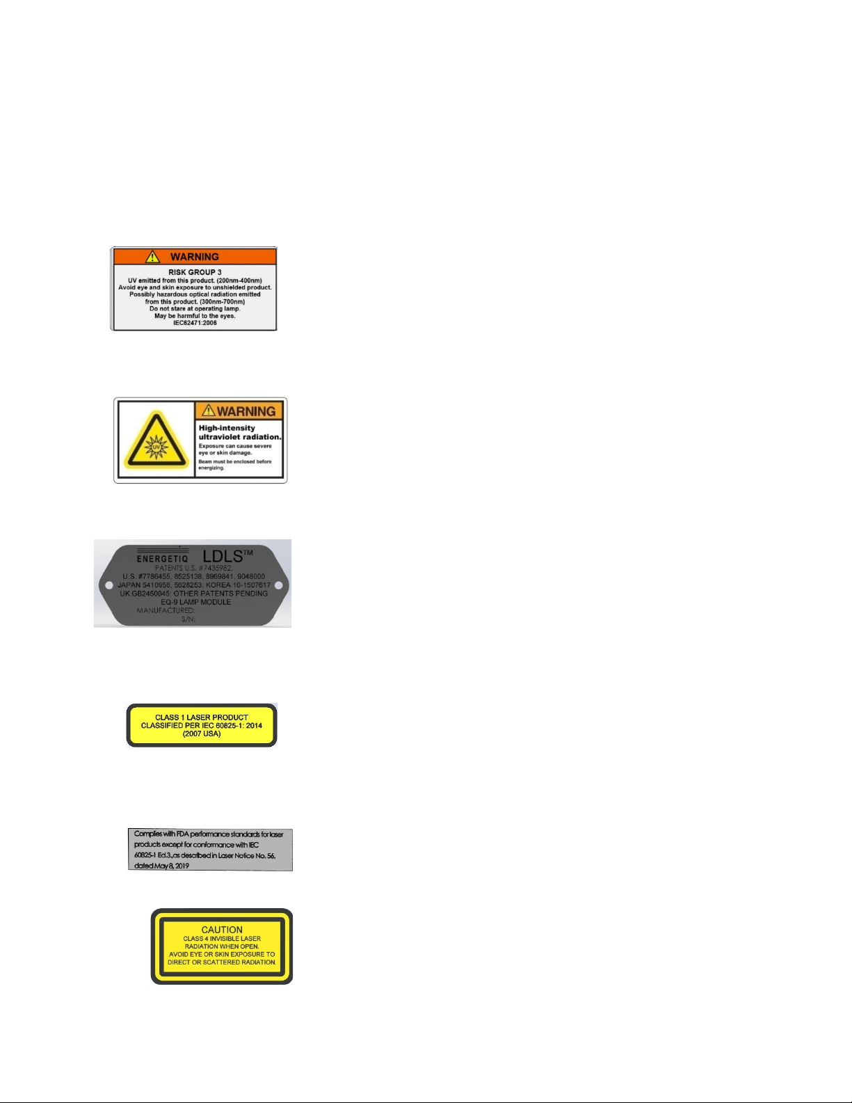
Labels and Safety Notification
The following safety labels appear on the product. Figure 1 shows the location of each label
on the EQ-9-HP system.
UV Hazard warning label –indicates hazardous levels of UV
light are present.
UV Hazard warning label –indicates hazardous levels of UV
light are present.
Manufacturer’s identification label – gives the manufacturer’s
name, the model number, serial number, and date of manufacture
of the equipment.
Explanatory label –states the classification of the laser product.
Class 1 is the lowest hazard level classification.
Certification label –states that the equipment has been tested
and verified to meet the standards indicated.
Non-interlocked housing label –notifies of a potential hazard
when covers are removed.
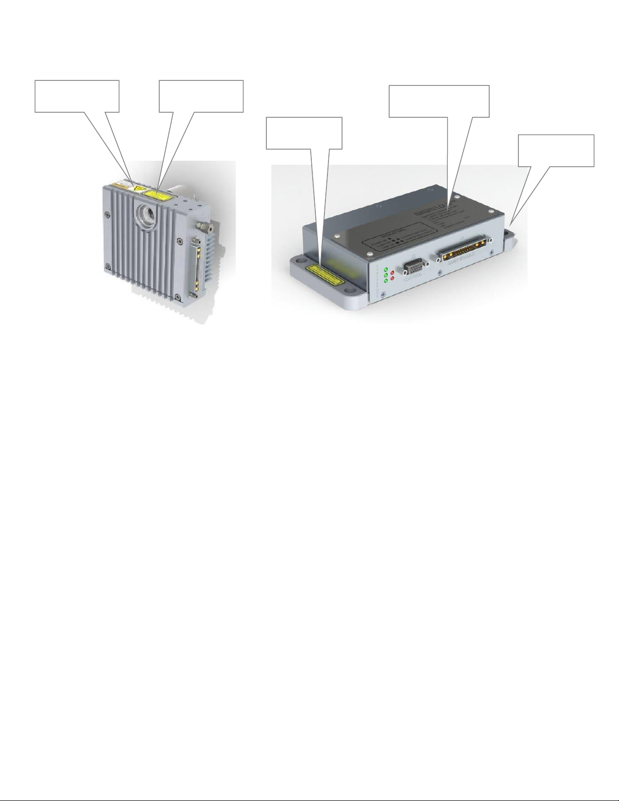
6 EQ-9-HP Operation Manual DOC-8240 Rev. 3
Figure 1: Safety Label Locations
Safety Interlocks
The EQ-9-HP is equipped with interlocks to prevent operation of the device when any of the
following conditions are present:
1. An external interlock is open
External Interlock
External interlock pins are provided for the customer’s use (see Chapter 3 for connection
details). Any suitable normally-open contact or solid-state switch can operate the interlock
circuit.
The interlock circuit must be connected to enable the operation of the unit. Should the
interlock connection open during operation or standby, the source is immediately disabled, and
all light output from the aperture ceases.
Certification
Label
Explanatory
Label
Manufacturer’s
Identification label
UV Hazard
Warning Label
Non-interlocked
Housing Label

DOC-8240 Rev. 3 EQ-9-HP Operation Manual 7
C h a p t e r 2
DESCRIPTION
General
The EQ-9-HP is a broad-band lamp system for use in a wide variety of applications. The lamp
produces high brightness, broad-band light from DUV wavelengths through visible and
beyond. The output is very stable, and has a long lifetime before any service is required. A
simple control interface ensures ease of use.
Some of the advantages of the EQ-9-HP include:
•Very high brightness across complete spectrum
–170nm through visible and beyond
•Eliminates need for multiple lamps (replaces D2/Tungsten/Xenon Arc)
–Simplified optical system
•Excellent spatial stability
–Repeatable measurements
•Superior short and long term power stability
–Repeatable measurements
•Electrodeless operation for long life
–Reduced consumable costs
–Minimal recalibration of instrument
The EQ-9-HP system consists of a Power Supply Controller unit, Lamp House unit, and
interconnecting cable. Connection to DC power is required for operation. Connection to
nitrogen purge gas is optional, but recommended in some cases. See Chapter 3 for connection
details.

8 EQ-9-HP Operation Manual DOC-8240 Rev. 3
Specifications
Physical Specifications
Dimensions (H x W x D)
•Lamp House: 109x 120 x 43 mm
•Power Supply Controller: 38 x 197 x 93mm
Weight
•Lamp House: 0.91 kg (2 lb)
•Power Supply Controller: 0.68 kg (1.5 lb)
Utility Requirements
•Electrical: 12VDC, 140W
•Cooling: Fan (30 CFM forced air cooling)
•Purge gas (optional): clean dry nitrogen, filtered (5um 20 psig (0.14 MPa) supply
pressure)
Remote Interface
Digital Inputs
•Type: Optocoupler LED
•Logic: Active High
•Input voltage: 5VDC
•Input current: 8mA
Digital Outputs
•Type: Open collector to ground (digital common)
•Logic: Active Low
•Voltage: 30VDC max.
•Sink current: 30mA max.
User Power
•Voltage: 5VDC, referenced to digital common
•Current: 50mA maximum

DOC-8240 Rev. 3 EQ-9-HP Operation Manual 9
Figure 2: Recommended Cooling Configuration
Environmental Requirements
Operating
•Ambient temperature: 15–30°C (with 30 CFM forced air cooling)
•Relative Humidity: non-condensing, 80% max. for temperatures up to 31°C,
decreasing linearly to 50% max. at 40°C.
•Pollution Degree 2 (normally only non-conductive pollution; occasional,
temporary condensation possible)
•Installation Category II
•Indoor use only
Transport
•Temperature: -5–95°C
•Relative Humidity: non-condensing, 95% max.
Recommended
Cooling Direction
[30 CFM]
10 EQ-9-HP Operation Manual DOC-8240 Rev. 3
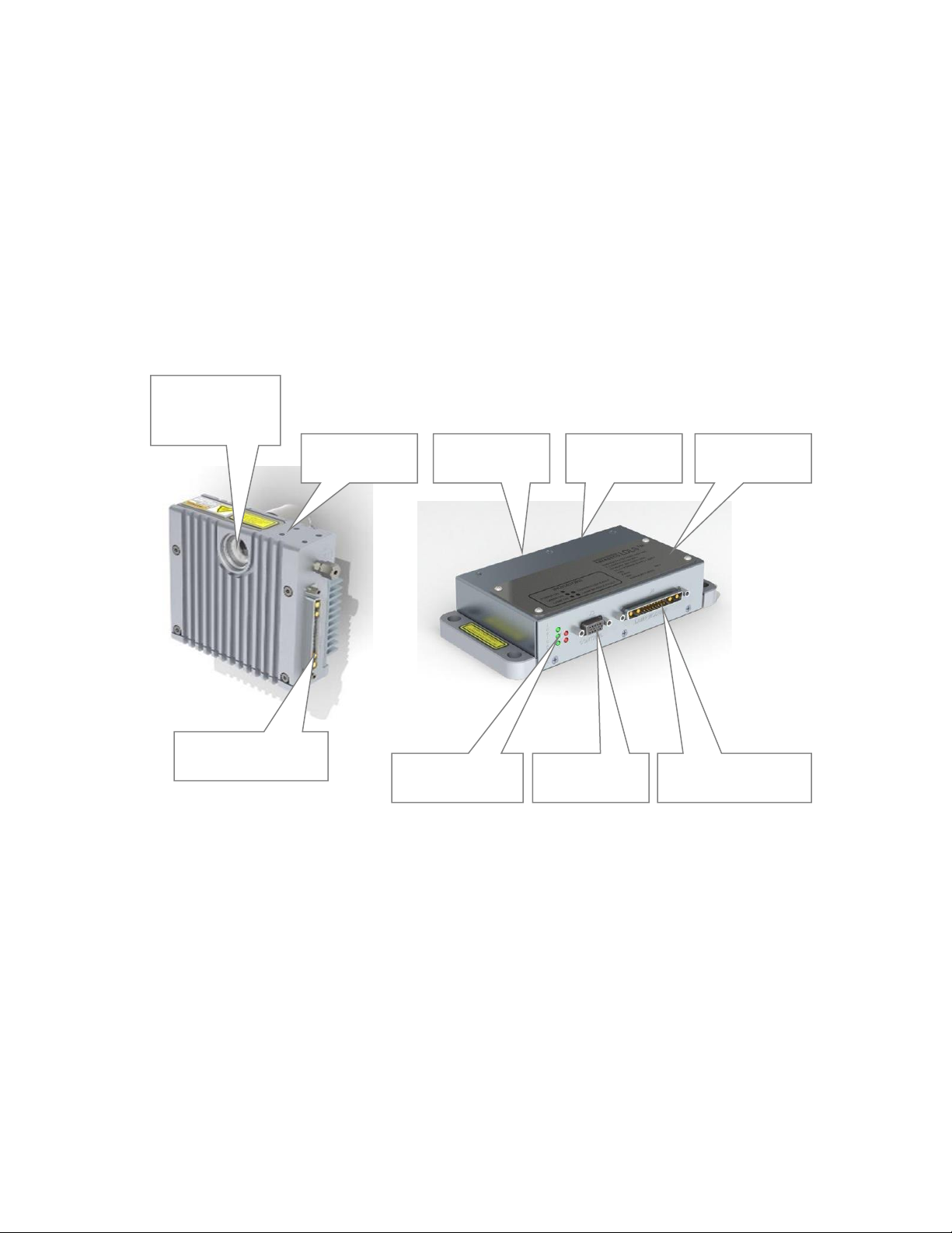
System Description
As shown in Figure the EQ-9-HP system consists of a Power Supply Controller unit, Lamp
House, Controller to Lamp house interconnect cable (not shown). Power and I/O interface
connections (also not shown) are either provided by the user or by Energetiq upon request.
The following sections provide descriptions of the system components and controls, and give
an overview of their functions. Refer to the “Installation” section of this manual (Chapter 3)
for more detailed information.
Figure 3: EQ-9-HP Lamp System
Lamp House Control
Connector
Lamp House Control
Connector
I/O Interface
Connector
Status Indicators
Optical Output
(Also opposite
side)
Lamp
House
Power Input
Connector
Power Supply
Controller
RS-485
Connector

DOC-8240 Rev. 3 EQ-9-HP Operation Manual 11
Power Supply Controller
The Power Supply Controller contains:
•Laser power supply
•Thermo-electric cooler control system for laser
•Control electronics
•Status indicator LEDs
•Interface connectors
External features (refer to Figure 3):
Status Indicator LEDs
These five LEDs indicate the system status. The function of these indicators is shown below
in Table 2.
LED Label
Meaning (when lit)
POWER ON
DC power is connected to the EQ-9-HP Power Supply Controller
LAMP ON
UV Light is on
LASER ON
Laser power is ON and laser light is being produced within the Lamp
House
CONTROLLER FAULT
One of the following has occurred in the Power Supply Controller:
1. External interlock open
2. Controller internal temperature too high
3. Laser power not reaching setpoint
4. Laser Temperature Fault
LAMP MODULE FAULT
One of the following has occurred in the Lamp House module:
1. Control Cable not connected properly
2. Lamphouse internal termperature too high
3. Ignition Failure
Table 2: Status Indicator LED Functions

12 EQ-9-HP Operation Manual DOC-8240 Rev. 3
Input/Output (I/O) Connector
Provides access to control and status signals. See Chapter 3 for pin assignments and functions.
This is the only operator interface to the EQ-9-HP –there are no local controls. Energetiq
offers the EQ-99-RC Remote Control Module which connects to the Input/Output
connector of the EQ-9-HP or EQ-99 and provides a means of local control. Contact
Energetiq for additional information.
Power Input Connector
This is a jack screw secured input connector for 12 VDC power. The EQ-9-HP can be
powered directly from a customer provided 12VDC power supply. See Chapter 3 for detailed
information.
Lamp House Control Connector (21-pin mixed D-sub)
Provides various power and control signals to/from the Lamp House module. No other
connector or cable may be used with the EQ-9-HP other than the one supplied.
DOC-8240 Rev. 3 EQ-9-HP Operation Manual 13
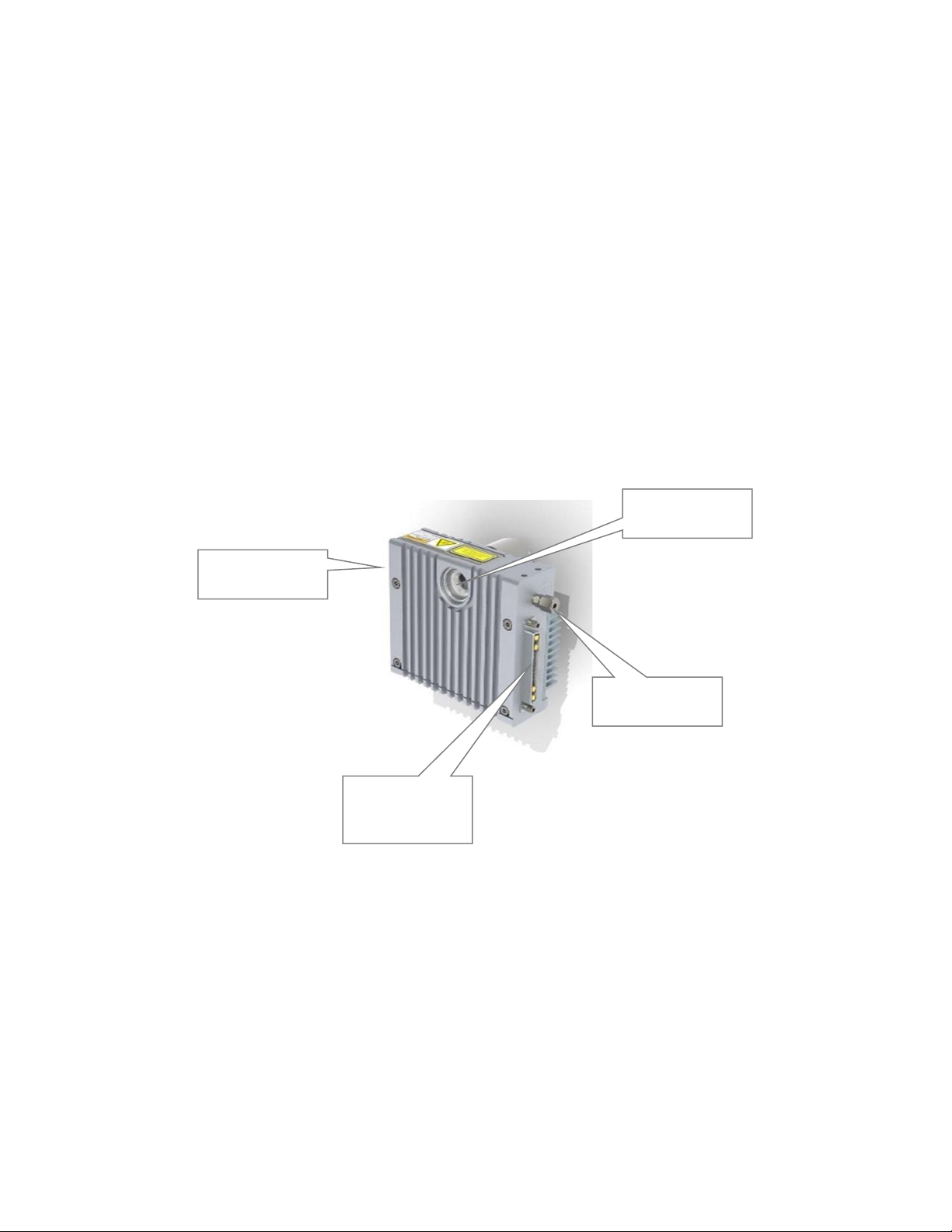
Lamp House
The Lamp House assembly contains:
•Lamp
•Igniter
•Laser
•Thermoelectric cooler
•IR pumping optics
•Output windows
•Laser ON indicator
•Interface connectors
Figure 4: Lamp House Assembly
External features (refer to Figure 4):
Lamp
Window (front)
Control
Connector (to
Controller)
Purge Gas
Port
Laser ON
Indicator

14 EQ-9-HP Operation Manual DOC-8240 Rev. 3
Lamp Windows
The lamp windows at the optical output provide protection from the high pressure bulb inside
the Lamp House. An internally-threaded SM1 adapter is provided for easy connection of
optical hardware.
Nitrogen Purge Inlet
This is the inlet fitting for nitrogen purge gas. Purge gas is optional but is recommended for
best performance when a deep UV bulb is provided. With no purge, ozone will form from
atmospheric oxygen and attenuate the light output in the 220 –280nm band. In addition,
atmospheric oxygen and water vapor will attenuate the output below 200nm. Bulbs chosen
for some OEM applications do not produce ozone and the purge fitting can be omitted.
There is no return fitting for the purge nitrogen. The purge flow normally escapes within the
Lamp House enclosure, and then to atmosphere.
Laser On Indicator
This LED is illuminated when the laser is ON.
Control Connector (21-pin mixed D-sub)
Provides various power and control signals to/from the Power Supply Controller. No other
connector or cable may be used with the EQ-9-HP other than the one supplied.

DOC-8240 Rev. 3 EQ-9-HP Operation Manual 15
C h a p t e r 3
INSTALLATION
Unpacking
Upon arrival, start by inspecting all parts of the system for completeness and any damage
incurred in shipping. The EQ-9-HP shipping box should contain:
1) EQ-9-HP Power Supply Controller unit
1) EQ-9-HP Lamp House unit
1) Black interconnecting cable from Lamp House to Power Supply Controller (21-
pin mixed D-sub).
OPTIONAL
1) EQ-99-RC Remote Control Module with interlock connector
1) I/O cable with 15 pin D- connector at each end
1) DC power supply with custom connector
If any part is missing or appears damaged, contact Energetiq immediately. Do not attempt to
substitute any parts. There are no user-serviceable parts inside the EQ-9-HP Lamp House or
Power Supply Controller unit.
Connections
Installation of the EQ-9-HP consists of connecting electrical and optional gas supplies, and
connecting the Lamp House module to the user’s equipment.
Electrical Power
The EQ-9-HP requires 12VDC at 11.7A minimum (140W rating). Power consumption is
approximately 100W during normal operation. Some OEM versions have higher current
requirements.

16 EQ-9-HP Operation Manual DOC-8240 Rev. 3
Power can be provided via a customer provided 12VDC power supply. The connector on the
EQ-9-HP is a jack screw secured connector. This protects from accidental removal of power
if the power cable is pulled. Connect to a 12VDC source as follows:
Connector
FCI DA3W3SA00LF
Pin A1
+12VDC
Pin A2
-12VDC return
Pin A3
Safety Ground
Purge Gas
Purge gas is optional but is recommended for best performance. With no purge, ozone will
form from atmospheric oxygen and attenuate the light output in the 220 –280nm band. In
addition, atmospheric oxygen and water vapor will attenuate the output below 200nm. Some
OEM units for near-UV and visible applications are equipped with bulbs which do not
produce ozone and the purge fitting may not be present.
If required, connect a source of nitrogen purge gas to the port on the Lamp House. The
fitting is a push-to-connect type, sized for 1/8" tubing.
Clean and dry nitrogen from either a Dewar or research-grade N2bottle is recommended. Do
not use any other purge gas. Grade 6 or better gas purity is recommended to maintain
cleanliness of the optics, and gas should be filtered to <5um. Supply pressure should be 20
psig (0.14 MPa). With a 20 psig inlet pressure, the EQ-9-HP will consume approximately 1 slm
of flow.
There is no return fitting for the purge nitrogen. The purge flow normally escapes within the
Lamp House enclosure, and then to atmosphere.
Optical Interface
The lamp windows accommodate light output of 0.56 NA. A pair of pins and four M4
threaded holes are available on the bottom of the EQ-9-HP for mounting. Four M4 threaded
holes are also available on the top surface of the Lamp House. An internally-threaded SM1
adapter is provided for connection of optical hardware. See Figure 5 below for mechanical
layout of the Lamp House.
Table of contents
Other Energetiq Lighting Equipment manuals


Popular Lighting Equipment manuals by other brands

Vision & Control
Vision & Control LDLF60x120-R633/UDC Instructions for use

AAA-LUX
AAA-LUX WS Series installation guide

Philips
Philips hue 17466 V7 Series user manual

BADU
BADU JET Perla translation of original operation manual

ubicquia
ubicquia ubihub AP6 installation guide
Ledj
Ledj Pixel Bar LEDJ73A user manual


Uplus Lighting
Uplus Lighting 37X15ZWASH user manual

MJ LED LIGHTNING
MJ LED LIGHTNING MJ-1350 user manual

THT-EX
THT-EX THT-L1219 operating instructions

Lena Lighting
Lena Lighting MAGNUM MULTI BATTERY L Installation instruction

Chauvet
Chauvet CF-NEONB30 user manual

Larson Electronics
Larson Electronics EPL-HB-100LED-RT-UVA-20C-EPP instruction manual