Energetiq LDLS EQ-99X-FC User manual
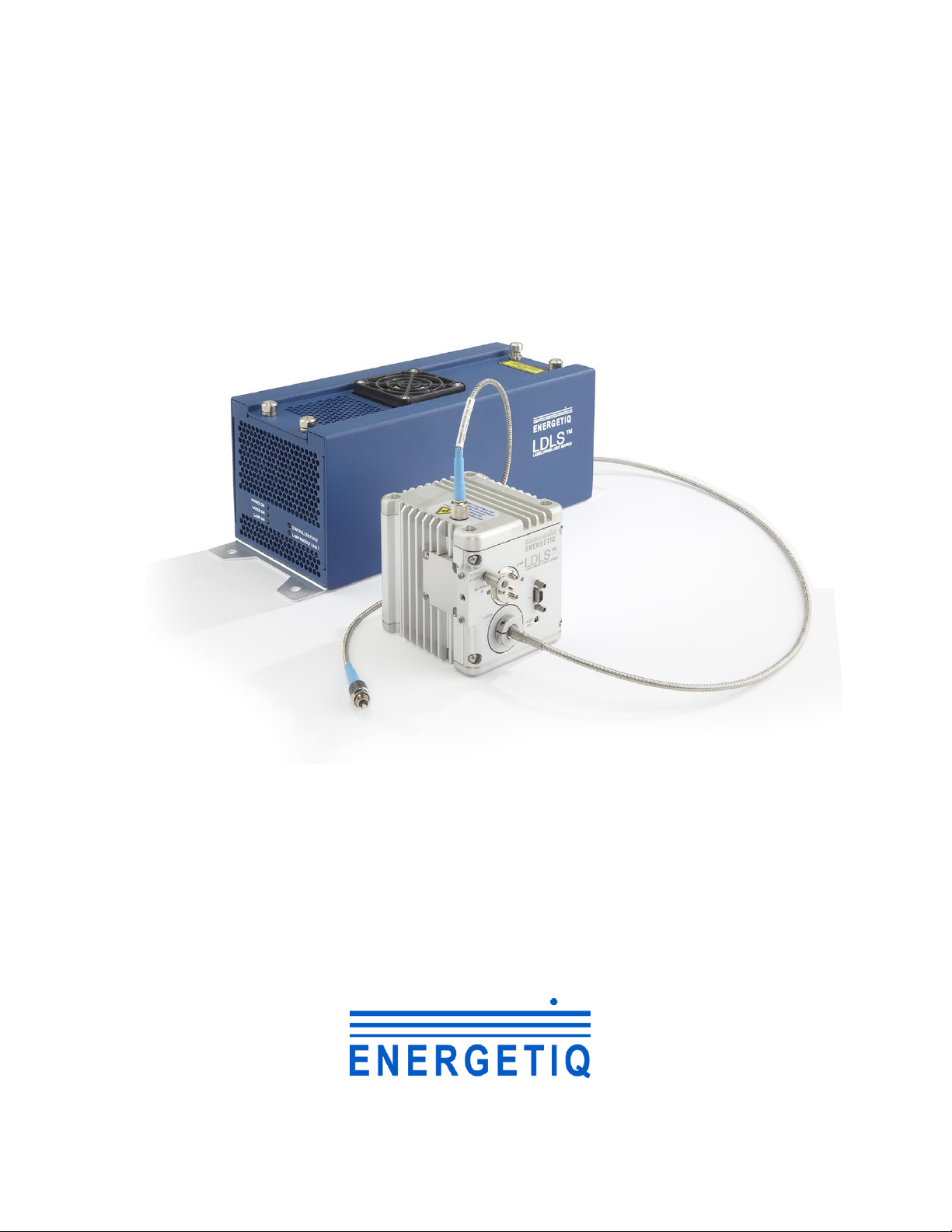
Model EQ-99X-FC
LDLS™
Laser-Driven Light Source
Operation and Maintenance Manual
Revision 3April 2018
Part Number DOC-6522

Copyright © 2018 Energetiq Technology Inc. All rights reserved.
Energetiq products are covered by the following patents: US 7435982, 7786455, 8525138,
8969841, 9048000, 9185786; Japan 5410958, 5628253; Korea 10-1507617; UK GB2450045.
All technical information, including drawings, schematics and specifications contained in this
manual are the property of Energetiq and shall not be reproduced in whole or in part without
the written consent of Energetiq. The content of this manual is subject to change without
notice.
Energetiq Technology Inc.
7 Constitution Way, Woburn, MA 01801 USA
Tel. +1 (781) 939-0763
Fax +1 (781) 939-0769
E-mail: service@energetiq.com
http://www.energetiq.com

Declaration of Conformity

Table of Contents
Chapter 1........................................................................................................................................................ 1
General Information........................................................................................................................... 1
Safety............................................................................................................................................... 1
Chapter 2........................................................................................................................................................ 8
Description ........................................................................................................................................... 8
General ........................................................................................................................................... 8
System Description .................................................................................................................... 11
Power Supply Controller........................................................................................................... 12
Lamp House................................................................................................................................ 14
Installation........................................................................................................................................... 16
Unpacking.................................................................................................................................... 16
Connections................................................................................................................................. 16
Installation Procedure................................................................................................................ 23
Chapter 4...................................................................................................................................................... 25
Operation............................................................................................................................................ 25
Starting.......................................................................................................................................... 25
Stopping ....................................................................................................................................... 25
Chapter 5...................................................................................................................................................... 27
EQ-99 SMA Fiber Cleaning Process................................Error! Bookmark not defined.
Troubleshooting ......................................................................................................................... 27
Lamp Replacement .................................................................................................................... 33
Appendix A................................................................................................................................................. 34
Revision Control................................................................................................................................ 34
DOC-6522 Rev. 3 EQ-99X-FC Operation Manual 1
Chapter 1
GENERAL INFORMATION
Safety
WARNING
CAUTION
The EQ-99 emits dangerous levels of UV
radiation. Even short exposures to skin or eyes
may cause burns. Ensure that only authorized
personnel are in the vicinity of source during
operation. Personnel in vicinity of operating
source should wear protective eyewear, clothing,
and gloves. Lighted UV warning lights and signs
posted on doors to lab areas may help prevent
accidental exposure.
This unit emits ultraviolet (UV) radiation that is
harmful to humans. Avoid exposure to the
direct or reflected output beam. Make certain
that the appropriate output beam shields and
optics are in place prior to energizing the unit.
All interlocks must be satisfied prior to
operation; failure to do so may lead to
hazardous conditions.

2 EQ99X-FC Operation Manual DOC-6522 Rev. 3
WARNING
General Precautions
The EQ-99X-FC should only be operated with a fiber connected to the broadband output and
connected using an FC connector. Operation without an FC terminated fiber in place will
result in hazardous broadband radiation. The far end of the output fiber should be terminated
into a closed beam tube. Due to the possibility of generating ozone when ambient oxygen is
exposed to short wavelength light, the beam should always be enclosed in an appropriate beam
pipe, tube, or enclosed space. We suggest purging any beam transport space with dry nitrogen
gas.
The EQ-99X-FC source must also be cabled correctly and connected to a socket with a
protective earth ground prior to operation.
Refer to the Installation section of this manual (Chapter 3) for details of the facilities
connections.
Other than a bulb replacement, there are no user-serviceable parts inside the EQ-99X-FC.
For any problems encountered during operation, please contact Energetiq Technology for
assistance. If there is a component failure, do not attempt to open the Power Supply
Controller or Lamp House enclosure of the EQ-99X-FC.
The EQ-99 controller utilizes an internal Class 4
IR laser capable of causing severe injury to eyes
or skin. Do not open or attempt to service this
unit. Contact Energetiq regarding any problems
with the unit.

DOC-6522 Rev. 3 EQ-99X-FC Operation Manual 3
The EQ-99X-FC utilizes a quartz lamp containing a high-pressure gas fill. Explosion
of the lamp and possible injury from flying fragments can occur if the lamp is
mishandled.
Do not open the enclosure of either the Lamp House enclosure or the Power Supply
Controller. Dangerous invisible infrared laser beams and hazardous voltages exist
inside the units. Opening the chassis both voids the warranty and exposes the user to
dangerous radiation and hazardous voltages.
CAUTION
Laser Information
The EQ-99X-FC uses a patented (U.S. Patent #7435982, 7786455, 7989786, others pending)
laser drive system to excite a plasma that radiates in the UV as well as the visible bands. A
class 4 laser is located in the Power Supply Controller enclosure. Laser energy is delivered via
an armored fiber to the Lamp House enclosure and connected with an SMA-type connector.
Safety interlocks shut down the laser power if the SMA connector is removed from the Lamp
House enclosure. The optical configuration of the Lamp House ensures that the direct laser
beam can not exit the unit. The EQ-99X-FC laser product is designated as Class 1 during all
normal operation.
Use of controls or adjustments or performance of procedures
other than those specified herein may result in hazardous
radiation exposure.

4 EQ99X-FC Operation Manual DOC-6522 Rev. 3
The parameters of the non-accessible internal laser are given below in Table 1.
Wavelength
974 nm
Emission Type
CW
Laser Power for classification
<1.38mW through a 7mm aperture
at 70mm
Beam Diameter
~3 mm at aperture
Divergence
>100 mRad
Transverse Beam Mode
Diffuse
Table 1: Embedded Laser Parameters
No regular service is required for the EQ-99X-FC. Any service to the system must be
performed only by factory authorized and trained technicians. To avoid injury, under no
circumstances should the user open or modify the Lamp House or Power Supply Controller
enclosure.
The unit must not be operated if the covers are removed or it is defective in any way. Contact
Energetiq if any problems with the equipment are suspected.
DOC-6522 Rev. 3 EQ-99X-FC Operation Manual 5
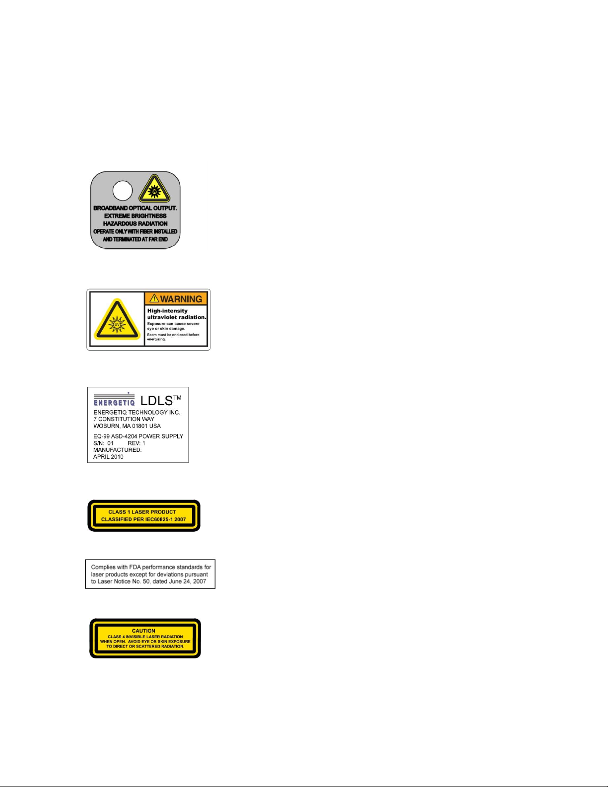
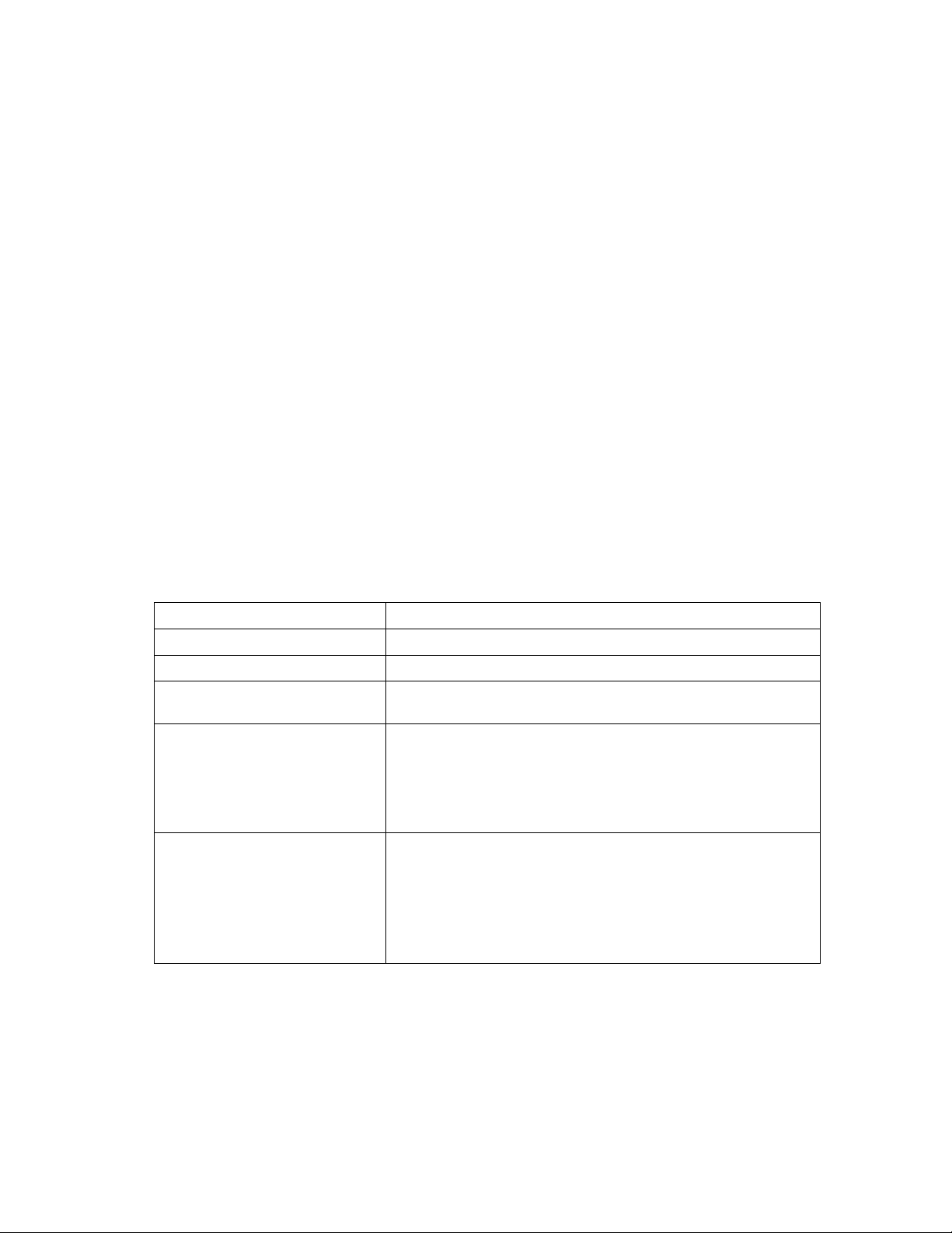
Labels and Safety Notification
The following safety labels appear on the product. Figure 1 shows the location of each label
on the EQ-99X-FC system.
Output Connector Warning Label –indicates hazardous levels
of broadband light are present. Unit should only be operated
with an output fiber installed to the EQ-99X-FC and the far
end of the fiber terminated so that the output beam remains
enclosed.
UV Hazard warning label –indicates hazardous levels of UV
light are present.
Manufacturer’s identification label – gives the manufacturer’s
name and address, and the model, serial number, and date of
manufacture of the equipment.
Explanatory label –states the classification of the laser product.
Class 1 is the lowest hazard level classification.
Certification label –states that the equipment has been tested
and verified to meet the standards indicated.
Non-interlocked housing label –notifies of a potential hazard
when covers are removed.

6 EQ99X-FC Operation Manual DOC-6522 Rev. 3
Figure 1: Safety Label Locations
Safety Interlocks
The EQ-99X-FC is equipped with interlocks to prevent operation of the device when any of
the following conditions are present:
1. Bulb is not properly installed into the Lamp House enclosure
2. The laser fiber is not properly connected to the Lamp House enclosure
3. An external interlock is open
External Interlock
External interlock pins are provided for the customer’s use (see Chapter 3 for connection
details). Any suitable normally-open contact or solid-state switch can operate the interlock
circuit.
Certification
Label
Explanatory
Label
Non-interlocked
Housing Label
Manufacturer’s
Identification label
UV Hazard
Warning Label
Output Connector
Warning Label
Manufacturer’s
ID Label
Non-Interlocked
Housing Label

DOC-6522 Rev. 3 EQ-99X-FC Operation Manual 7
The interlock circuit must be connected to enable the operation of the unit. Should the
interlock connection open during operation or standby, the source is immediately disabled, and
all light output from the aperture ceases.

8 EQ99X-FC Operation Manual DOC-6522 Rev. 3
Chapter 2
DESCRIPTION
General
The EQ-99X-FC is a broad-band lamp system for use in a wide variety of applications. The
lamp produces high brightness, broad-band light from DUV wavelengths through visible and
beyond. The output is very stable, and has a long lifetime before any service is required. A
simple control interface ensures ease of use.
Some of the advantages of the EQ-99X-FC include:
Very high brightness across complete spectrum
–170nm through visible and beyond
Eliminates need for multiple lamps (replaces D2/Tungsten/Xenon Arc)
–Simplified optical system
Excellent spatial stability
–Repeatable measurements
Superior short and long term power stability
–Repeatable measurements
Electrodeless operation for long life
–Reduced consumable costs
–Minimal recalibration of instrument
The EQ-99X-FC system consists of a Power Supply Controller unit, Lamp House unit, and
interconnecting cables. Connection to DC power is required for operation. Connection to
nitrogen purge gas is optional, but recommended for best performance. See Chapter 3 for
connection details.
DOC-6522 Rev. 3 EQ-99X-FC Operation Manual 9
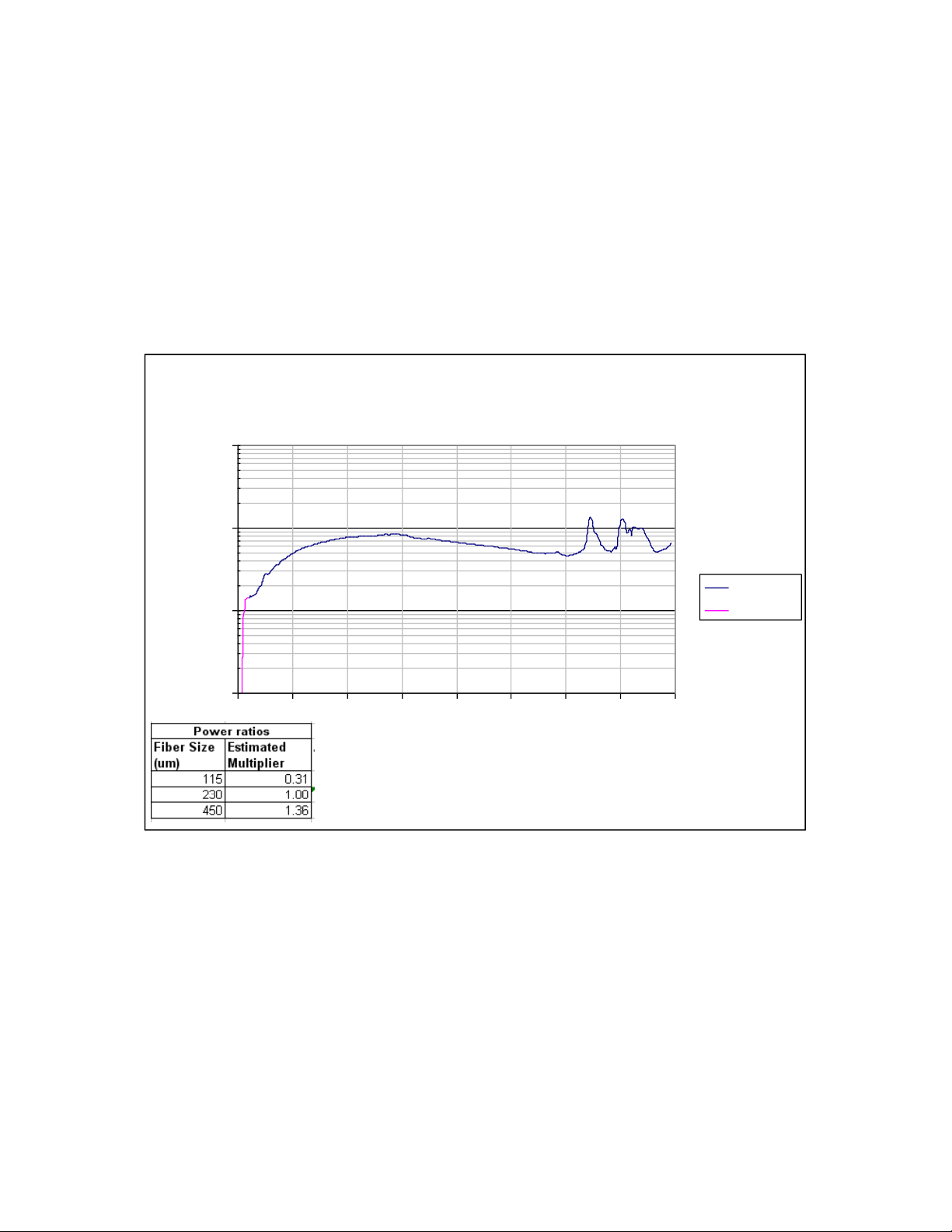
Specifications
Optical Performance
Typical output spectrum: see Figure 2.
Figure 2: Typical Output Spectrum
Physical Specifications
Dimensions (H x W x D)
Lamp House: 82 x 86 x 76 mm (3.2 x 3.4 x 3.0 in)
Power Supply Controller: 113 x 111 x 299 mm (4.4 x 4.4 x 11.8 in)
Weight
Lamp House: 0.7 kg (1.5 lbs)
Power Supply Controller: 1.4 kg (3.0 lbs)
EQ-99X-FC Spectral Power Fiber Output
230um Energetiq Fiber, 1m long
1
10
100
1000
180 280 380 480 580 680 780 880 980
Wavelength (nm)
uW/nm
Measured
Estimated

10 EQ99X-FC Operation Manual DOC-6522 Rev. 3
Utility Requirements
Electrical: 12VDC, 140W
Cooling: natural convection and internal fan, no auxiliary cooling necessary
Purge gas (optional): clean dry nitrogen, filtered to 5um 20 psig (0.14 MPa) supply
pressure
Remote Interface
Digital Inputs
Type: Optocoupler LED
Logic: Active High
Input voltage: 5VDC
Input current: 8mA
Digital Outputs
Type: Open collector to ground (digital common)
Logic: Active Low
Voltage: 30VDC max.
Sink current: 30mA max.
User Power
Voltage: 5VDC, referenced to digital common
Current: 50mA maximum
Environmental Requirements
Operating
Ambient temperature: 15–35°C
Relative Humidity: non-condensing, 80% max. for temperatures up to 31°C,
decreasing linearly to 50% max. at 40°C.
Pollution Degree 2 (normally only non-conductive pollution; occasional,
temporary condensation possible)
Installation Category II
Indoor use only
Transport
Temperature: -5–95°C
Relative Humidity: non-condensing, 95% max.

DOC-6522 Rev. 3 EQ-99X-FC Operation Manual 11
System Description
As shown in Figure 3 the EQ-99X-FC system consists of a Power Supply Controller unit,
Lamp House, laser fiber optic cable, and Lamp House signal cable (not shown). Power and
I/O interface connections (also not shown) are provided by the user.
The following sections provide descriptions of the system components and controls, and gives
an overview of their functions. Refer to the “Installation” section of this manual (Chapter 3)
for more detailed information.
Figure 3: EQ-99X-FC Lamp System
Status Indicators
(on rear panel)
Lamp
House
Fault Status
Indicators
Optical Output
Fiber
I/O Interface Connector
(rear panel)
Power Supply
Controller
12 VDC Input Connector
(rear panel)
Status
Indicators
Armored Laser
Fiber
12 EQ99X-FC Operation Manual DOC-6522 Rev. 3
Power Supply Controller
The Power Supply Controller contains:
IR Diode Laser
Laser power supply
Thermo-electric cooler for laser
Permanently attached, armored laser fiber optic cable
Control electronics
Status indicator LEDs
Interface connectors
External features (refer to Figure 3):
Status Indicator LEDs
These five LEDs indicate the system status. The function of these indicators is shown below
in Table 2.
LED Label
Meaning (when lit)
POWER ON
DC power is connected to the EQ-99X-FC Power Supply Controller
LAMP ON
UV Light is on
LASER ON
Laser power is ON and laser light is being delivered to the Lamp
House
CONTROLLER FAULT
One of the following has occurred in the Power Supply Controller:
1. External interlock open
2. Controller internal temperature too high
3. Laser power not reaching setpoint
4. Laser Temperature Fault
LAMP MODULE FAULT
One of the following has occurred in the Lamp House module:
1. Control Cable not connected properly
2. Lamphouse internal termperature too high
3. Laser fiber not correctly connected
4. Bulb not correctly installed
5. Ignition Failure
Table 2: Status Indicator LED Functions

DOC-6522 Rev. 3 EQ-99X-FC Operation Manual 13
Input/Output (I/O) Connector
Provides access to control and status signals. See Chapter 3 for pin assignments and functions.
This is the only operator interface to the EQ-99X-FC –there are no local controls. Energetiq
offers the EQ-99-RC Remote Control Module which connects to the Input/Output
connector and provides a means of local control. Contact Energetiq for additional
information.
Power Input Connector
This is a latching input connector for 12 VDC power. Power can be provided using the
optional PS00018 12VDC power supply. Alternatively, the EQ-99X-FC can be powered
directly from a customer provided 12VDC power supply. See Chapter 3 for detailed
information.
Lamp House Signal Connector (mini D sub –9-pin)
Provides various power and control signals to/from the Lamp House module. No other
connector or cable may be used with the EQ-99X-FC other than the one supplied.
Armored Laser Fiber
The laser light is delivered from the Power Supply Controller to the Lamp House via a fiber
optic cable with armored protection. The fiber is permanently attached to the Power Supply
Controller, and connected to the Lamp House by an SMA-type connector.
It is critical that this armored fiber be treated with care and inspected for any abnormalities
prior to operation. Avoid sharp bends, which will permanently damage the fiber. Minimum
bend radius is 30mm (1.18 in). Avoid crimping or compressing the fiber. See Chapter 3 for
more information on installation and end face cleaning.
14 EQ99X-FC Operation Manual DOC-6522 Rev. 3
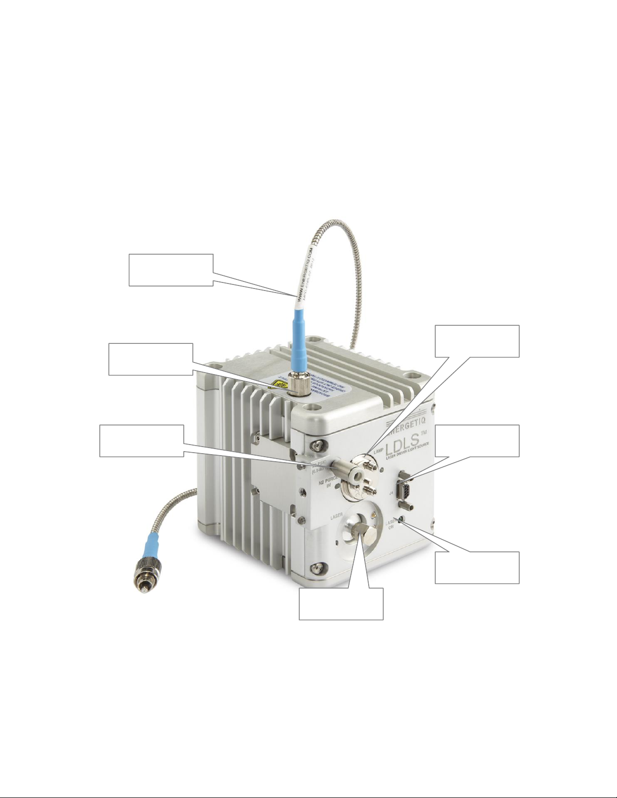
Lamp House
The Lamp House assembly contains:
Lamp
Igniter
IR pumping optics
Output window
Laser ON indicator
Interface connectors
Figure 4: Lamp House Assembly
FC Output
Connector
Laser Input
(SMA-type)
Laser ON
Indicator
Purge Gas
Port
Signal Connector
(to Controller)
Lamp mounting
flange
Optical fiber
output cable

DOC-6522 Rev. 3 EQ-99X-FC Operation Manual 15
External features (refer to Figure 4):
FC Output Connector
Provides broadband optical output using a standard FC connector. Energetiq recommends the
use of an Energetiq-supplied fiber for the broadband output. These fibers are able to
withstand the very high power density of deep UV radiation that is generated by the EQ-99X-
FC, thus giving best longevity and performance.
Nitrogen Purge Inlet
This is the inlet fitting for nitrogen purge gas. Purge gas is optional but is recommended for
best performance. With no purge, ozone will form from atmospheric oxygen and attenuate
the light output in the 220 –280nm band. In addition, atmospheric oxygen and water vapor
will attenuate the output below 200nm.
There is no return fitting for the purge nitrogen. The purge flow normally escapes within the
Lamp House enclosure, and then to atmosphere.
Laser Input
This is the inlet connector for the armored fiber from the Power Supply Controller. It
contains a set of interlock pins that disable the laser when the SMA connector is not properly
in place.
Laser On Indicator
This LED is illuminated when the laser is ON.
J4 Signal Connector (mini D sub –9-pin)
Provides various power and control signals to/from the Power Supply Controller. No other
connector or cable may be used with the EQ-99X-FC other than the one supplied.

16 EQ99X-FC Operation Manual DOC-6522 Rev. 3
Chapter 3
INSTALlATION
Unpacking
Upon arrival, start by inspecting all parts of the system for completeness and any damage
incurred in shipping. The EQ-99X-FC shipping box should contain:
1) EQ-99X-FC Power Supply Controller unit
1) EQ-99X-FC Lamp House unit
1) Black interconnecting cable from Lamp House to Power Supply Controller (9
pin mini D-sub).
OPTIONAL
EQ-99-RC Remote Control Module with interlock connector and I/O cable
PS00018 12 VDC Power Supply (universal input voltage)
UVFIBER-115-1M-FC 115um Output Fiber, 1m long
UVFIBER-115-2M-FC 115um Output Fiber, 2m long
UVFIBER-230-1M-FC 230um Output Fiber, 1m long
UVFIBER-230-2M-FC 230um Output Fiber, 2m long
UVFIBER-450-1M-FC 450um Output Fiber, 1m long
UVFIBER-450-2M-FC 450um Output Fiber, 2m long
Use care when unpacking to avoid damaging the armored fiber optic cable.
If any part is missing or appears damaged, contact Energetiq immediately. Do not attempt to
substitute any parts. There are no user-serviceable parts inside the EQ-99X-FC Lamp House
or Power Supply Controller unit.
Connections
Installation of the EQ-99X-FC consists of connecting electrical and gas supplies, and
connecting the Lamp House module to the user’s equipment.
Table of contents
Other Energetiq Lighting Equipment manuals


Popular Lighting Equipment manuals by other brands

Jandy
Jandy WaterColors LED installation manual

Domus
Domus BOLT-60 installation manual

Ledj
Ledj Slimline 7HEX6 Series user manual

Intex
Intex Krystal Clean Poolwater 8220 owner's manual

DTS
DTS Thomas & Betts NT 06 Mounting and Maintenance Instructions

LED Lighting
LED Lighting STAGE PRO SPOT 2000 PC user manual


Osram
Osram BY-P28 user manual
Osram
Osram TRAXON Media Pixel Ribbon DMX Outdoor Flat Mounting guide

Schwaiger
Schwaiger WLED210 Operating instructions and safety instructions

EUROLAMP
EUROLAMP 147-56060 quick start guide

Mega Pool Saver
Mega Pool Saver MPS-1100 Programming guide

Digital Sputnik
Digital Sputnik VOYAGER manual