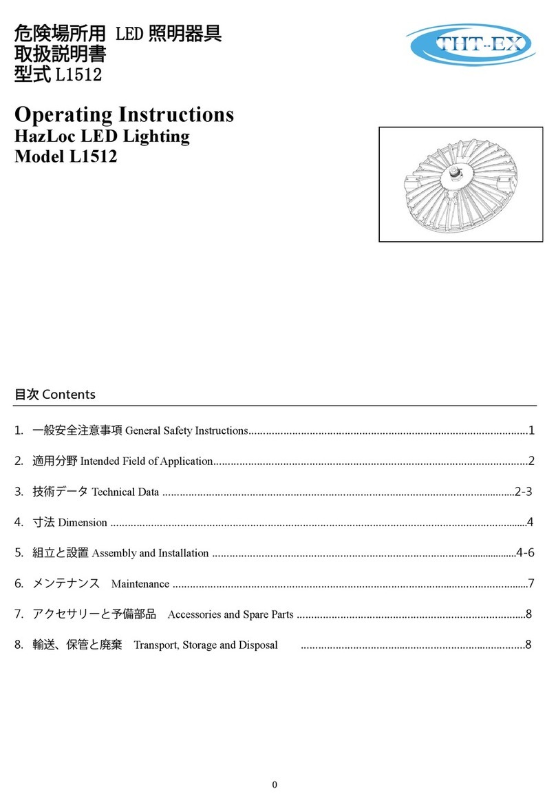
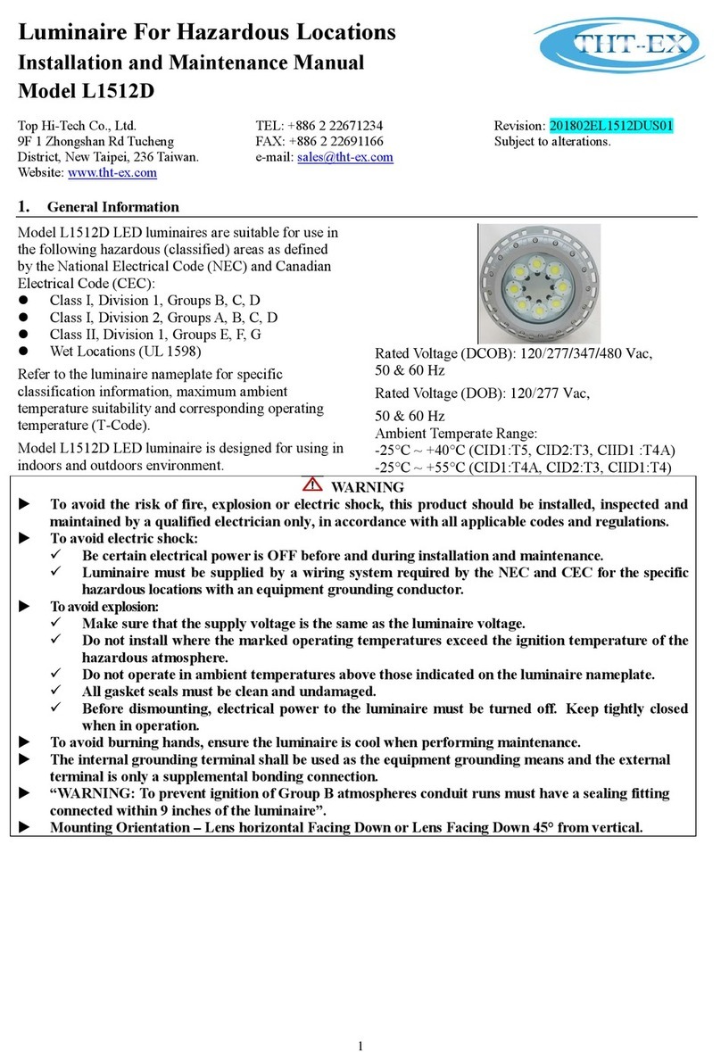
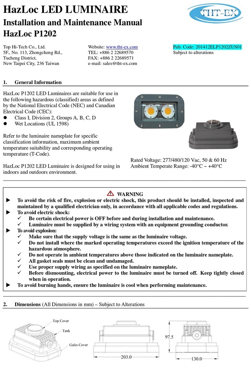
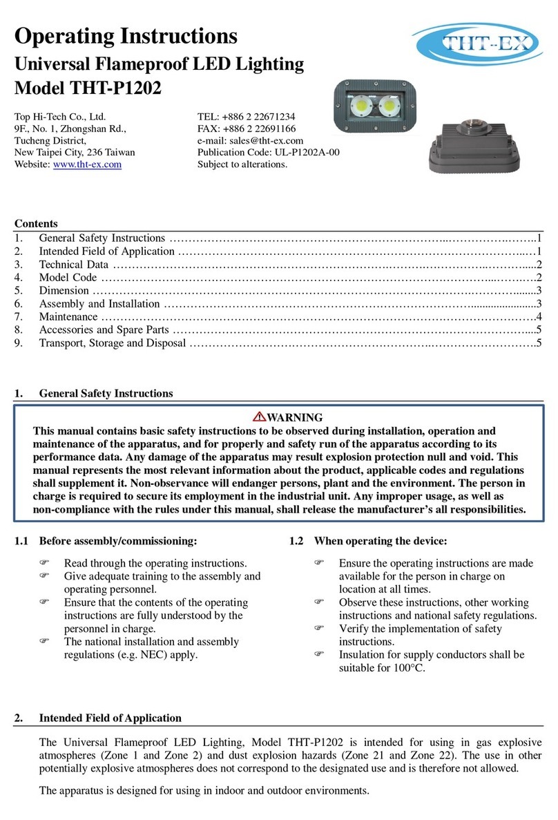
THT-EX THT-L1219 User manual

1
Operating Instructions
Universal Explosion Proof LED Lighting
Model THT-L1219
Top Hi-Tech Co., Ltd.
5F., No. 113, Zhongcheng Rd.,
Tucheng District,
New Taipei City, 236 Taiwan
Website: www.tht-ex.com
TEL: +886 2 22689570
FAX: +886 2 22689571
e-mail: sales@tht-ex.com
Revision: EX-L1219-01
Subject to alterations.
Contents
1. General Safety Instructions ………………………………………………………………..…………….……..1
2. Intended Field of Application ………………………………………………………………………………..…1
3. Technical Data ……………………………………………………………….……….……………..……….....2
4. Model Code …………………………………………………………………………………………...…….….2
5. Dimension ……………………………………………………………………………………….………….......2
6. Assembly and Installation ……………………………………………………………………….......................3
7. Maintenance …………………………………………………………………………………………………….4
8. Accessories and Spare Parts …………………………………………………………………………………....4
9. Transport, Storage and Disposal ……………………………………………………….……………………….4
1. General Safety Instructions
1.1 Before assembly/commissioning:
Read through the operating instructions.
Give adequate training to the assembly and
operating personnel.
Ensure that the contents of the operating
instructions are fully understood by the
personnel in charge.
The national installation and assembly
regulations (e.g. IEC/EN 60079-14) apply.
1.2 When operating the device:
Ensure the operating instructions are made
available for the person in charge on
location at all times.
Observe these instructions, other working
instructions and national safety regulations.
Verify the implementation of safety
instructions.
2. Intended Field of Application
The Universal Explosion Proof LED Lighting, Model THT-L1219 is intended for using in gas explosive
atmospheres (Zone 1 and Zone 2 according to IEC60079-10-1) and dust explosion hazards (Zone 21 and Zone
22 according to IEC60079-10-2). The use in other potentially explosive atmospheres does not correspond to the
designated use and is therefore not allowed.
The apparatus is designed for using in indoor and outdoor environments.
WARNING
This manual contains basic safety instructions to be observed during installation, operation and
maintenance of the apparatus, and for properly and safety run of the apparatus according to its
performance data. Any damage of the apparatus may result explosion protection null and void. This manual
represents the most relevant information about the product, applicable codes and regulations shall
supplement it. Non-observance will endanger persons, plant and the environment. The person in charge is
required to secure its employment in the industrial unit. Any improper usage, as well as non-compliance
with the rules under this manual, shall release the manufacturer’s all responsibilities.

2
3. Technical Data
Item
L1219A
L1219B
L1219C
L1219D
Explosion Protection
IECEx
Gas Explosion
Protection
Dust Explosion
Protection
ATEX
Gas Explosion
Protection
Dust Explosion
Protection
Ex d IIB+H2 T6 Gb
Ex tb IIIC T...°C
II 2 G Ex d IIB+H2 T6 Gb
II 2 D Ex tb IIIC T...°C Db
Ex d IIB+H2 T5 Gb
Ex tb IIIC T...°C
II 2 G Ex d IIB+H2 T5 Gb
II 2 D Ex tb IIIC T...°C Db
Ex d IIB+H2 T5 Gb
Ex tb IIIC T...°C
II 2 G Ex d IIB+H2 T5 Gb
II 2 D Ex tb IIIC T...°C Db
Ex d IIB+H2 T6 Gb
Ex tb IIIC T...°C
II 2 G Ex d IIB+H2 T6 Gb
II 2 D Ex tb IIIC T...°C Db
Color of LED light
Cool White, Warm White,
Green & Red
Cool White & Warm White
Cool White & Warm White
Blue, Green, Red & Yellow
Number of LED module
1
5
4
warning light set
Color, Rated Voltage and
Wattage of LED
See section 4:Model Code
Power Factor
cos φ ≧0.9
Ambient Temperate Range
-20°C ~ +40°C
Degree of Protection
IP64
Material
Enclosure: Aluminum alloy; Glass: Tempered glass
LED Service Life
60,000 hrs
Entrance Hole
Tall Top Cover:
4×G3/4” threaded holes
Short Top Cover:
1×G3/4” threaded hole
Tall Top Cover:
4×G3/4” threaded holes
Short Top Cover:
1×G3/4” threaded hole
Tall Top Cover:
4×G3/4” threaded holes
Short Top Cover:
1×G3/4” threaded hole
Tall Top Cover:
1×G3/4” threaded hole
Cable Gland
G3/4 x 1.814; 7 ... 12mm
Fitting Cable
Size of Tube
Fitting Cable
ID:Ø8.0, L=25.6mm
OD: Ø7.0~ Ø8.0
ID:Ø8.5, L=25.6mm
OD: Ø7.5~ Ø8.5
ID:Ø10.0, L=25.6mm
OD: Ø9.0~ Ø10.0
ID:Ø12.0, L=25.6mm
OD: Ø11.0~ Ø12.0
Weight/Top Cover Type
Tall
Short
Tall
Short
Tall
Short
Tall
Without mounting bracket
7.9kg
7.5kg
9.5kg
8.9kg
9.1kg
8.5kg
7.7kg
Wall mounting
8.4kg
7.8kg
10kg
9.4kg
9.6kg
9.0kg
9.0kg
Hanging mounting
8.4kg
7.8kg
10kg
9.4kg
9.6kg
9.0kg
9.0kg
Ceiling mounting
8.7kg
8.1kg
10.3kg
9.7kg
9.9kg
9.3kg
9.3kg
Stanchion mounting 25°
9.3kg
8.7kg
10.9kg
10.3kg
10.5kg
9.9kg
9.9kg
Stanchion mounting 90°
9.1kg
8.5kg
10.7kg
10.1kg
10.3kg
9.7kg
9.7kg
Pendant mounting
8.4kg
7.8kg
10kg
9.4kg
9.6kg
9kg
9kg
4. Model Code
4.1 L1219A
(1)
(2)
(3)
(4)
(5)
(6)
(7)
(8)
(9)
THT-EX
1219
*
*
S
*
1
*
-*
(1) Brand name.
(2) Series designation, 1219=L1219 series.
(3) C.C.T., C=Cool white, W=Warm white, R=Red light, G=Green light.
(4) Voltage, A=24Vac, B=100Vac, C=110Vac, D=200Vac, E=220Vac, F=120Vac, G=208Vac.
(5) Type of LED carrier, S=Short Cylinder.
(6) Type of Top Cover, A=Tall type (L1105T), B=Short type (L1105S).
(7) LED quantity, 1=1 LED.
(8) LED watts choose, 1=10W, 2=20W, 3=33W.
(9) Mounting type. W25=Wall mounting 25°; W90= Wall mounting 90°; H25=Hanging mounting 25°; H90= Hanging
mounting 90°; C90=Ceiling mounting 90°; S25=Stanchion mounting 25°; S90=Stanchion mounting 90°; P30=Pendant
mounting.
Remarks:
1.33W for Green and Red LED light source is not available.
2.24V Cool white and Warm white LED light source can be used with 20watt model only.
3.Green Light and Red Light LED source can be used with 10W and 20W under work voltage 220V only.

3
4.2 L1219B
(1)
(2)
(3)
(4)
(5)
(6)
(7)
(8)
(9)
THT-EX
1219
*
*
C
*
5
*
-*
(1) Brand name
(2) Series designation, 1219=L1219 series.
(3) C.C.T., C=Cool white, W=Warm white.
(4) Voltage, A=24Vac, B=100Vac, C=110Vac, D=200Vac, E=220Vac, F=120Vac, G=208Vac.
(5) Type of LED carrier, C=Cylinder.
(6) Type of Top Cover, A=Tall type (L1105T), B=Short type (L1105S).
(7) LED quantity, 5=5 LEDs.
(8) LED watts choose, 1=10W, A=10W+20W, B=10W+33W, D=10W+20W+33W.
(9) Mounting type. W25=Wall mounting 25°; W90= Wall mounting 90°; H25=Hanging mounting 25°; H90= Hanging
mounting 90°; C90=Ceiling mounting 90°; S25=Stanchion mounting 25°; S90=Stanchion mounting 90°; P30=Pendant
mounting.
Remarks:
1.When LED watts choose is “1,” it consists of 10W LED, the highest wattage is 50W.
2.When LED watts choose is “A,” it consists of 10W and 20W LED, the highest wattage is 90W.
3.When LED watts choose is “B,” it consists of 10W and 33W LED, the highest wattage is 73W.
4.When LED watts choose is “D,” it consists of 10W, 20W and 33W LED, the highest wattage is 83W.
4.3 L1219C
(1)
(2)
(3)
(4)
(5)
(6)
(7)
(8)
(9)
THT-EX
1219
*
*
T
*
4
*
-*
(1) Brand name
(2) Series designation, 1219=L1219 series.
(3) C.C.T., C=Cool white, W=Warm white.
(4) Voltage, A=24Vac, B=100Vac, C=110Vac, D=200Vac, E=220Vac, F=120Vac, G=208Vac.
(5) Type of LED carrier, T=Triangular.
(6) Type of Top Cover, A=Tall type (L1105T), B=Short type (L1105S).
(7) LED quantity, 4=4 LEDs.
(8) LED watts choose, 1=10W, 2=20W, A=10W+20W, B=10W+33W, D=10W+20W+33W.
(9) Mounting type. W25=Wall mounting 25°; W90= Wall mounting 90°; H25=Hanging mounting 25°; H90= Hanging
mounting 90°; C90=Ceiling mounting 90°; S25=Stanchion mounting 25°; S90=Stanchion mounting 90°; P30=Pendant
mounting.
Remarks:
1. When LED watts choose is “1,” it consists of 10W LED, the highest wattage is 40W.
2. When LED watts choose is “2,” it consists of 20W LED, the highest wattage is 80W.
3. When LED watts choose is “A,” it consists of 10W and 20W LED, the highest wattage is 70W.
4. When LED watts choose is “B,” it consists of 10W and 33W LED, the highest wattage is 63W.
5. When LED watts choose is “D,” it consists of 10W, 20W and 33W LED, the highest wattage is 73W.
6. When voltage is 24V, only 80W is available.
4.4 L1219D
(1)
(2)
(3)
(4)
(5)
(6)
(7)
(8)
(9)
THT-EX
1219
*
*
W
A
0
1
-*
(1) Brand name
(2) Series designation, 1219=L1219 series.
(3) C.C.T., B=Blue light, Y=Yellow light, R=Red light, G=Green light.
(4) Voltage, A=24Vac, B=100Vac, C=110Vac, D=200Vac, E=220Vac, F=120Vac, G=208Vac.
(5) Type of LED carrier, W=Warning Light.
(6) Type of Top Cover, A=Tall type (L1105T).
(7) LED quantity, 0=Warning light set.
(8) LED watts choose, 1=10W.
(9) Mounting type. W25=Wall mounting 25°; W90= Wall mounting 90°; H25=Hanging mounting 25°; H90= Hanging
mounting 90°; C90=Ceiling mounting 90°; S25=Stanchion mounting 25°; S90=Stanchion mounting 90°; P30=Pendant
mounting.

4
5. Dimensions (All Dimensions in mm) – Subject to Alterations
Tall Top Cover Type
Short Top Cover Type
6. Assembly and Installation
6.1 Electrical Connection
Overview
A: Top Cover
B: M6 Screw×4
1: Sleeve
2: O-Ring
3: Connector (G 3/4”)
4: Pressure nut
5: Washer
6: Tube
7: Washer
8: O-Ring
9: Body
10: O-Ring
11: M4 Screw×2
12: Nut Plate
13: M4 Socket Set Screw×1
Cable Entries
6.1.1.1 Short Type of Top Cover
This Short Type of Top Cover is equipped with one cable entry hole by mounting a Cable Gland. To mount the Cable
Gland proceed as follows:
Electrical Connection
Loosen the 4×M6-screw (B) of Top Cover (A) of
the luminaire.
Disassemble the Cable Gland; assemble the Body
(9) and O-ring (10) of Cable Gland and tighten the
Body (9) with the entry hole of the Top Cover, 650
kgf-cm.
Insert the cable from outside trough each parts of
Cable Gland and the Top Cover (A) which has
been tightened with Body (9) of Cable Gland.
Introduce the wires of the luminary with wires of
the cable by attached closed-end-terminals as
following (see right picture):
White-wire connects to Neutral;
Red-wire connects to Live;
Green-wire connects to Ground.
Re-attach the Top Cover and tighten it by using
the respective M6 screws (B), 24.5 kgf-cm.
Green:
Ground wire
Red: Live wire
White:
Neutral wire
4

5
Orderly assemble the O-ring (8), Washers (7) & (5) and Tube (6), and Screw tighten Pressure nut (4) with the
Body of Cable Gland by appropriate tool, 600 kgf-cm.
Screw and tighten the M4 Socket Set Screw (13), 24.5 kgf-cm.
Position the Nut Plate, then screw and tighten the 2 M4 screws provided, 24.5 kgf-cm.
Assemble the O-ring (2) with the Connector (3), and attach the Sleeve (1) with the Main Body (9).
Check the tightness of the Cable Gland and Top Cover, ensure the IP protection guaranteed. The Cable Gland
is assembled completely.
Assemble the Cable Gland by following procedure:
Step 1
Step 2
Make sure above red-line areas have been set with
matching O-Rings. Check below 7 parts are contained:
①Body②Nut Plate③Washer④Tube ⑤Pressure Nut
⑥Connector⑦Sleeve
Note:
The cable must be certified with EN/IEC.
Insert the cable into and through each part of Cable
Gland successively, as set forth in above picture. Use
watertight tape to twist round the screw part as red
circle of above picture.
Note:
It's recommended to twist round the screw part with 3-
circle.
Step 3
Step 4
Connect the Green-wire with the Ground-wire, connect
the White-wire with the Neutral-wire and connect the
Red-wire with the Live-wire by using the Closed-end-
terminal, then put the said wires in the connection
chamber of lighting fixture.
Note:
1. Pull the wires to ensure the Closed-end-terminal
are fixed.
2. Ensure the description of voltage on the cables fit
with the requirement of use.
Tighten the Cable Gland with the entry hole of cable of
lighting fixture by using a wrench.
Note:
1. Torque Range: 65N.m.
2. O-Ring used in the connection area of Cable Gland
and the lighting fixture, as red circle area on above
picture, should not be pressed and extended over
the outside diameter of Cable Gland.
1
2
3
4
5
6
7

6
Step 5
Step 6
Put the parts that are worn by the cable as described in
the Step 2 into the Cable Gland, then clockwise screw
the "Pressure Nut" with 60N.m torque range, as set
forth on above picture.
Note:
Please see the left picture to learn how to screw the
Pressure Nut.
Press the Nut Plate against the cable and use M4
screws to fix the Pressure Nut with cable. Use a M4
screw to fix the cable from the side face of the Pressure
Nut, as set forth on above left picture.
Note:
Make sure the M4 screws are completely tightened to
make the cable be fully fixed.
Step 7
Step 8
Put the "Connector" in the volume of "Sleeve" and
tighten the "Sleeve" with the body of Cable Gland, as
above picture.
Completion of the Cable Gland setting.
6.1.1.2 Tall Type of Top Cover
This Tall Type of Top Cover is designed with four
cable entry holes that users can choose either of
them connecting the power as necessary. (See
right picture).
Choose a cable entry hole as necessary and mount
the Cable Gland with the top cover and introduce
wires of the luminary with wires of outside cable
by following the steps as described in the section
of Electrical Connection of 6.1.1.1 –Short Type of
Top Cover.
Rest of cable entry holes that are not used for
electrical connection should be tightened by the
plug nut, 650 kgf-cm,as provided, to ensure the
protection of flame-proof does work effectively.
6.2 Mounting Bracket Installation
6.2.1 Wall/Hanging Mount Bracket
The mount bracket is for the use of both wall
mount (Figure 1) and hanging mount (Figure 2).
Position the bracket holders and fix it by means of
the provided M6 screws, 24.5 kgf-cm.
Secure the wall mounting bracket to the structure
by using four fasteners (M8/SUS316, not
provided).
The lighting can be adjusted to 25°and 90°.
Figure 1
Figure 2

7
6.2.2 Ceiling Mount Bracket
The mount bracket is for the use of ceiling mount
(Figure 3).
Position the bracket holders and fix it by means
of the provided M6 screws, 24.5 kgf-cm.
Secure the wall mounting bracket to the structure
by using four fasteners (M8/SUS316, not
provided).
6.2.3 Pendant mount
The mounting type is for the use of bending tube
mounting (Figure 4).
Tube mounting thread is M35.
Thread the tube mounting on conduit and torque
until wrench-tight as requirement, 6600 kgf-cm.
6.2.4 Stanchion 25° & 90°
The mounting types are for the use of bending
tube mounting, 25° & 90° (Figure 5, 6).Tube
mounting thread is M35.
Thread the tube mounting on conduit and torque
until wrench-tight as requirement, 6600 kgf-cm.
6.3 Ground wire
External earth screw location as showing in the Red Circle of below pictures.
The external earth ground wire installation and terminal type as show the following picture.
Ground wire cross-sectional area=4mm²,max LED current=1A; @V=110Vac-10%.
Both ground screw and washer material is M4*5 stainless steel.
Torque Requirement: 7 kgf.cm.
Screw material is SUS316.
Ensure wire is tied assured.
Figure 5
Figure 6
Figure 3
Figure 4
O Type
U Type
5

8
6.4 Putting into Service
Before putting into operating, it’s necessary to ensure that:
the lighting is correctly installed.
the connection has been correctly made.
the cable has been inserted correctly.
7. Maintenance
7.1 Regular Maintenance
Consult the relevant national regulations (e.g. IEC/EN 60079-17) to determine the type and extent of
inspections.
Arrange the plan of regular inspection with the equipment, one time per 3-month at least, so that any defects
in the equipment which may be anticipated are promptly detected.
To check as part of the maintenance schedule as following:
Cracks or damages on the glass cover and/or on the enclosure.
Condition of the connecting cables.
Screws of the mounting bracket are tightened.
8. Accessories and Spare Parts
9. Transport, Storage and Disposal
Transport and storage is only allowed in the original packaging, on the way pointed out on the carton
box.
Transport –Shock-free in its original carton, do not drop, and handle carefully.
Store –Store in a dry place in its original packaging.
Disposal –Ensure environmentally friendly disposal of all components according to the legal
regulations.
WARNING
To avoid dangers due to energized parts, all connections and wiring must be disconnected from the
power supply. Secure the connections against unauthorized activation.
To avoid risk of burn to hands, let the housing, the cable gland and the protective glass cool down for
approximate 30 minutes before touching them.
Maintenance work is not permitted on flameproof enclosures. Repairs are only to be carried out by
the manufacturer. Unauthorized repair shall cause the manufacturer’s liability and warranty
expires.
WARNING
Use only original THT-EX accessories and spare parts. For accessories and spare parts, see data sheet at
www.tht-ex.com.
Table of contents
Other THT-EX Lighting Equipment manuals
Popular Lighting Equipment manuals by other brands
LIGMAN
LIGMAN FORREY 3 installation manual

ML Accessories
ML Accessories UNDKIT3WWW Installation & maintenance manual
Kogan
Kogan KAMODLGT10A user guide

ADB Safegate
ADB Safegate RELIANCE Intelligent Lighting Platform III user manual

Jandy
Jandy APURE35 Installation and operation manual

Laserworld
Laserworld CS-300G DMX user manual

