Energy zeroCO2 Island 3.6 kW User manual

zeroCO2Island
Ibrid Off-Grid Inverter
Operation Manual
TM019 Rev.007

. 2 .
Quick Guide
First start up
After making all the connections as per the diagrams provided in the manual, start the inverter.

. 3 .

. 4 .
Table of contents
1. About this manual ......................................................................................... 6
1.1 Purpose.................................................................................................. 6
1.2 Scope..................................................................................................... 6
2. Safety instructions........................................................................................ 7
2.1 Safety standards .................................................................................... 7
3. Introduction ................................................................................................... 8
3.1 Features ................................................................................................. 8
3.2 Basic System Architecture ..................................................................... 8
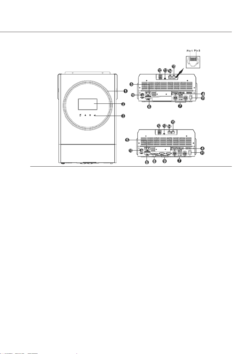
3.3 Product Overview................................................................................... 9
4. Installation ....................................................................................................10
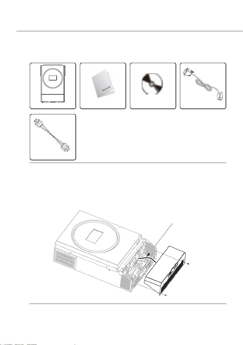
4.1 Unpacking and Inspection.....................................................................10
4.2 Preparation............................................................................................10
4.3 Mounting the Unit..................................................................................11
4.4 Battery Connection ...............................................................................12
4.5 AC Input/Output Connection.................................................................14
4.6 PV Connection ......................................................................................16
4.6.1 PV Module Selection ............................................................................. 17
4.7 Final Assembly......................................................................................18
4.8 Communication Connection..................................................................18
4.8.1 Serial Connection .................................................................................. 18
4.8.2 Wi-Fi Connection ................................................................................... 18
4.8.3 BMS Communication ............................................................................. 18
4.9 Dry Contact Signal............................................................................... 20
5. Operation ......................................................................................................21
5.1 Power ON/OFF .....................................................................................21
5.2 Operation and Display Panel ................................................................21
5.3 LCD Display Icons................................................................................ 22
5.4 LCD Setting.......................................................................................... 26
5.4.1 General Setting......................................................................................26
5.5 USB Function Setting........................................................................... 39
5.6 LCD Display ..........................................................................................41
5.7 Operating Mode Description ................................................................ 49
5.8 Faults Reference Code ........................................................................ 53
5.9 Warning Indicator................................................................................. 54
5.10 Battery equalization ........................................................................... 55
6. Specications.............................................................................................. 57
7. Trouble shooting ......................................................................................... 60
Appendix I: Parallel function.......................................................................... 62
Appendix II: BMS Communication Installation .............................................. 82
Appendix III: Wi-Fi Operation Guide ..............................................................91

. 5 .

. 6 .
1. About this manual
1.1 Purpose
This manual describes the assembly, installation, operation and troubleshooting of this unit.
Please read this manual carefully before installations and operations. Keep this manual for
future reference.
1.2 Scope
This manual provides safety and installation guidelines as well as information on tools and
wiring.

. 7 .
2. Safety instructions
2.1 Safety standards
This chapter contains important safety and operating instructions. Read and keep this manual
for future reference.
• Before using the unit, read all instructions and cautionary markings on the unit, the batteries
and all appropriate sections of this manual.
Caution.
To reduce risk of injury, charge only deep-cycle lead acid type rechargeable batteries.
Other types of batteries may burst, causing personal injury and damage.
• Do not disassemble the unit. Take it to a qualied service center when service or repair is
required. Incorrect re-assembly may result in a risk of electric shock or re.
• To reduce risk of electric shock, disconnect all wirings before attempting any maintenance or
cleaning. Turning off the unit will not reduce this risk.
Caution.
Only qualied personnel can install this device with battery.
Caution.
Never charge a frozen battery.
• For optimum operation of this inverter/charger, please follow required spec to select
appropriate cable size. It’s very important to correctly operate this inverter/charger.
• Be very cautious when working with metal tools on or around batteries. A potential risk exists
to drop a tool to spark or short circuit batteries or other electrical parts and could cause an
explosion.
• Please strictly follow installation procedure when you want to disconnect AC or DC terminals.
Please refer to INSTALLATION section of this manual for the details.
• Fuses are provided as over-current protection for the battery supply.
• GROUNDING INSTRUCTIONS -This inverter/charger should be connected to a permanent
grounded wiring system. Be sure to comply with local requirements and regulation to install
this inverter.
• NEVER cause AC output and DC input short circuited. Do NOT connect to the mains when
DC input short circuits. .
Warning. Only qualied service persons are able to service this device. If errors still
persist after following troubleshooting table, please send this inverter/charger back to
local dealer or service center for maintenance.
Warning. Because this inverter is non-isolated, only three types of PV modules are
acceptable: single crystalline, poly crystalline with class A-rated and CIGS modules. To
avoid any malfunction, do not connect any PV modules with possible current leakage
to the inverter. For example, grounded PV modules will cause current leakage to the
inverter. When using CIGS modules, please be sure NO grounding.
Caution. It’s required to use PV junction box with surge protection. Otherwise, it will
cause damage on inverter when lightning occurs on PV modules.

. 8 .
3. Introduction
zeroCO2Island is a multi-function inverter, combining functions of inverter, solar charger and
battery charger to offer uninterruptible power support in a single package. The comprehensive
LCD display offers user-congurable and easy-accessible button operations such as battery
charging current, AC or solar charging priority, and acceptable input voltage based on different
applications.
3.1 Features
• Pure sine wave inverter
• Customizable status LED ring with RGB lights
• Touchable button with 4.3" colored LCD
• Built-in Wi-Fi for mobile monitoring (APP is available)
• Supports USB On-the-Go function
• Data log events stored in the inverter
• Built-in anti-dusk kit
• Reserved communication port for BMS
• Battery independent function
• Parallel operation up to 9 units.
3.2 Basic System Architecture
The following illustration shows basic application for this unit. It also required the following
devices to have a complete running system:
• Generator or Utility mains.
• PV modules
Consult with your system integrator for other possible system architectures depending on your
requirements.
This inverter can power various appliances in home or ofce environment, including motor-type
appliances such as tube light, fan, refrigerator and air conditioners.
Figure 3.1 - Basic hybrid PV System Overview

. 9 .
3. Introduction
3.3 Product Overview
Figure 3.2 - For parallel installation and operation, please check Appendix I
1. RGB LED ring (refer to LCD Setting section for the details)
2. LCD display
3. Touchable Function keys
4. PV connectors
5. 3.6 kW version: AC input connectors
6 kW Twin version: AC output connectors (Load connection)
6. 3.6 kW version: AC output connectors (Load connection)
6 kW Twin version: AC input connectors
7. Battery connectors
8. Current sharing port
9. Parallel communication port
10. Circuit breaker
11. Power switch
12. Dry contact
13. USB port as USB communication port and USB function port
14. RS-232 communication port
15. BMS communication port: CAN, RS-485 or RS-232

. 10 .
4. Installation
4.1 Unpacking and Inspection
Before installation, please inspect the unit. Be sure that nothing inside the package is damaged.
You should have received the following items inside of package:
Inverter unit Manual
Current
parallel
cable
Software CD RS-232 cable
Figure 4.1 - Packing list
4.2 Preparation
To make the electrical connections, unscrew the cover screws and partially remove it. Attention:
in the cover there is an electrical connection with the inverter which cannot be removed.
Connessione elettrica fissa
Fixed electrical connection
Figure 4.2 - Bottom cover removal

. 11 .
4. Installation
4.3 Mounting the Unit
Consider the following points before selecting where to install:
• Do not mount the inverter on ammable construction materials.
• Mount on a solid surface
• Install this inverter at eye level in order to allow the LCD display to be read at all times.
• The ambient temperature should be between -10°C and 50°C to ensure optimal operation.
• The recommended installation position is to be adhered to the wall vertically.
• Be sure to keep other objects and surfaces as shown in the right diagram to guarantee
sufcient heat dissipation and to have enough space for removing wires.
Warning.
SUITABLE FOR MOUNTING ON CONCRETE OR OTHER NON-COMBUSTIBLE
SURFACE ONLY.
• Install the unit by screwing three screws. It’s recommended to use M4 or M5 screws.
Figure 4.3 - Keep distances Figure 4.4 - Inverter screws position

. 12 .
4. Installation
4.4 Battery Connection
Caution. For safety operation and regulation compliance, it’s requested to install a
separate DC over-current protector or disconnect device between battery and inverter.
It may not be required to have a disconnect device in some applications, however, it’s
still required to have over-current protection installed. Please refer to typical amperage
in below table as required fuse or breaker size.
Warning.
All wiring must be performed by a qualied
personnel.
Warning. It’s very important for system safety and
efcient operation to use appropriate cable for
battery connection. To reduce risk of injury, please
use the proper recommended cable and terminal
size as below.
Model
[kW]
Amperage
[A]
Battery
Capacity
Wire Size
[AWG]
Ring terminal Torque
[Nm]
mm2D[mm] L[mm]
3.6 100 200Ah 1*4 22 6.4 33.5 2 ~ 3
6 Twin 137 1*2 / 2*6 28 42.7
Table 4.1 - Recommended battery cable and terminal size
Please follow below steps to implement battery connection:
1. Assemble battery ring terminal based on recommended battery cable and terminal size.
2. Insert the ring terminal of battery cable atly into battery connector of inverter and make sure
the nuts are tightened with torque of 2-3 Nm. Make sure polarity at both the battery and the
inverter/charge is correctly connected and ring terminals are tightly screwed to the battery
terminals.
Figure 4.5 - Ring terminal

. 13 .
4. Installation
Figure 4.6 - Installation
Warning. Shock Hazard. Installation must be performed with care due to high battery
voltage in series.
Caution.
Do not place anything between the at part of the inverter terminal and the ring
terminal. Otherwise, overheating may occur.
Caution.
Do not apply anti-oxidant substance on the terminals before terminals are connected
tightly.
Caution.
Before making the nal DC connection or closing DC breaker/disconnector, be sure
positive (+) must be connected to positive (+) and negative (-) must be connected to
negative (-).

. 14 .
4. Installation
4.5 AC Input/Output Connection
Caution. Before connecting to AC input power source, please install a separate AC
breaker between inverter and AC input power source. This will ensure the inverter can
be securely disconnected during maintenance and fully protected from over current of
AC input.
Caution. There are two terminal blocks with “IN” and “OUT” markings. ENSURE that
utility AC input is connected to IN and load AC to OUT and not the wrong way round
and also that Line and Neutrals are connected correctly.
Warning.
All wiring must be performed by qualied personnel.
Warning. It’s very important for system safety and efcient operation to use
appropriate cable for AC input connection. To reduce risk of injury, please use the
proper recommended cable size as below.
Model
[kW]
Gauge
[AWG]
Torque
[Nm]
3.6 12 1.2 ~ 1.6
6 Twin 10
Table 4.2 - Suggested cable requirement for
AC wires
L N
Cable ground Line Neutral
Color yellow-green brown or black blue
Table 4.3 - AC cable denition
Please follow below steps to implement AC input/output connection:
1. Before making AC input/output connection, be sure to open DC protector or disconnector
rst.
2. Remove insulation sleeve 10mm for six conductors. And shorten phase L and neutral
conductor N 3 mm.
3. Insert AC input wires according to polarities indicated on terminal block (Figure 4.7 and
Figure 4.8) and tighten the terminal screws. Be sure to connect PE protective conductor
rst.
Warning. Be sure that AC power source is disconnected before attempting to
hardwire it to the unit.
4. Then, insert AC output wires according to polarities indicated on terminal block (Figure 4.9 and
Figure 4.10) and tighten terminal screws. Be sure to connect PE protective conductor rst.
5. Make sure the wires are securely connected.

. 15 .
4. Installation
Figure 4.7 - 3.6 kW AC input wires
Figure 4.8 - 6 kW Twin AC input wires
Figure 4.9 - 3.6 kW AC output wires Figure 4.10 - 6 kW Twin AC output wires

. 16 .
4. Installation
Caution.
Important: be sure to connect AC wires with correct polarity. If L and N wires are
connected reversely, it may cause utility short-circuited when these inverters are
worked in parallel operation.
Caution.
Appliances such as air conditioner are required at least 2~3 minutes to restart
because it’s required to have enough time to balance refrigerant gas inside of circuits.
If a power shortage occurs and recovers in a short time, it will cause damage to your
connected appliances. To prevent this kind of damage, please check manufacturer of
air conditioner if it’s equipped with time-delay function before installation. Otherwise,
this inverter/charger will trig overload fault and cut off output to protect your appliance
but sometimes it still causes internal damage to the air conditioner.
4.6 PV Connection
Caution. Before connecting to PV modules, please install separately a DC circuit
breaker between inverter and PV modules.
Caution.
Please install a surge protection device between inverter and PV modules and the
recommended voltage is 500V.
Warning.
Do switch off the inverter before connecting to PV modules. Otherwise, it will cause
inverter damage.
Warning.
Do NOT connect negative and positive terminal of PV modules to the ground.
Warning.
All wiring must be performed by qualied personnel.
Warning.
It's very important for system safety and efcient operation to use appropriate cable for
PV module connection. To reduce risk of injury, please use the proper recommended
cable size as below.
Model
[kW]
Amperage
[A]
Cable Size
[AWG]
Torque
[Nm]
3.6 18 12 1.2 ~ 1.6
6 27 10
Table 4.4 - PV recommended cable size

. 17 .
4. Installation
4.6.1
PV Module Selection
When selecting proper PV modules, please be sure to consider below parameters:
• Open circuit Voltage (Voc) of PV modules not exceeds max. PV array open circuit voltage of
inverter.
• Open circuit Voltage (Voc) of PV modules should be higher than min. battery voltage.
Model 3.6 kW 6 kW Twin
Max. PV Array Open Circuit Voltage [Vdc] 500 500
PV Array MPPT Voltage Range [Vdc] 120 ~ 430
MPP Number 1
Table 4.5 - Solar Charging Mode
Please follow below steps to implement PV module connection:
1. Remove insulation sleeve 10 mm for positive and
negative conductors.
2. Check correct polarity of connection cable from PV
modules and PV input connectors. Then, connect
positive pole (+) of connection cable to positive pole
(+) of PV input connector. Connect negative pole (-)
of connection cable to negative pole (-) of PV input
connector.
Figure 4.12 - PV modules connection cable
Figure 4.11 - insulation sleeve

. 18 .
4. Installation
PV Module Spec (Table 4.6):
• Peak power 250W;
• Voltage at maximum power: 30.7Vdc
• Imp: 8.15A
• Voc: 37.4Vdc
• Isc: 8.63A
• Celle: 60
Total solar input
power [W]
Solar input Q'ty of modules
1500 6 pieces in series 6 pcs
2000 8 pieces in series 8 pcs
2750 11 pieces in series 11 pcs
3000 6 pieces in series 2 strings in parallel 12 pcs
4000 8 pieces in series 2 strings in parallel 16 pcs
5000 10 pieces in series 2 strings in parallel 20 pcs
6000 12 pieces in series 2 strings in parallel 24 pcs
Table 4.6 - Recommended PV module Conguration
4.7 Final Assembly
After connecting all wirings, please put bottom cover back by screwing two screws as shown in
Figure 4.13.
4.8 Communication Connection
4.8.1
Serial Connection
Please use the supplied serial cable to connect between the inverter and your PC. Install the
monitoring software from the bundled CD and follow the on-screen instructions to complete
your installation. For detailed software operation, refer to the software user manual on the
bundled CD.
4.8.2
Wi-Fi Connection
This unit is equipped with a Wi-Fi transmitter. Wi-Fi transmitter can enable wireless
communication between off-grid inverters and monitoring platform. Users can access and
control the monitored inverter with downloaded APP. You may nd “WatchPower” app from the
Apple® Store or “WatchPower Wi-Fi” in Google® Play Store. All data loggers and parameters
are saved in iCloud (Figure 4.14). For quick installation and operation, please refer to Appendix
III: Wi-Fi Operation Guide at page 91 for details.
4.8.3
BMS Communication
It is recommended to purchase a special communication cable if you are connecting to Lithium-
Ion battery banks. Please refer to Appendix II: BMS Communication Installation at page 82 for
details.

. 19 .
4. Installation
Figure 4.13 - Bottom cover Figure 4.14 - App monitoring
RS-232 communication cable
USB
communication
cable
BMS
communication cable
Figure 4.15 - BMS Communication

. 20 .
4. Installation
4.9 Dry Contact Signal
There is one dry contact (3A/250VAC) available on the rear panel.
It could be used to deliver signal to external device when
battery voltage reaches warning level.
Unit Status Condition
NC & C NO & C
Power Off Unit is off and no output is powered. Close Open
Power On Output is
powered
from
Battery
power
or Solar
energy.
Program 01
set as USB
(utility rst) or
SUB (solar
rst)
Battery voltage < Low
DC warning voltage Open Close
Battery voltage > Set-
ting value in Program
13 or battery charging
reaches oating stage
Close Open
Program
01 is set as
SBU (SBU
priority)
Battery voltage < Set-
ting value in Program
12
Open Close
Battery voltage > Set-
ting value in Program
13 or battery charging
reaches oating stage
Close Open
Table 4.7 - Dry Contact Signal
NC NOC
This manual suits for next models
1
Table of contents
Other Energy Inverter manuals
Popular Inverter manuals by other brands

Sungrow
Sungrow SH3K6-30 user manual

Hopewind
Hopewind hopeSun Series Quick installation guide

Xantrex
Xantrex RV2012GS owner's manual

Alpha Group
Alpha Group OutBack Power GS3548E installation manual

Alpha Outback Energy
Alpha Outback Energy Radian Series quick start guide

Audiovox
Audiovox ADC180 owner's manual