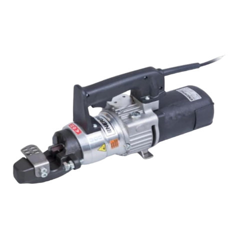
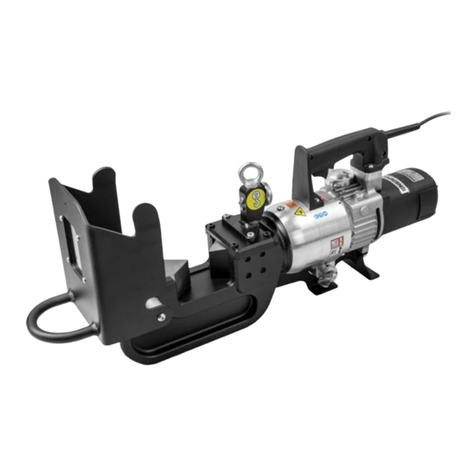
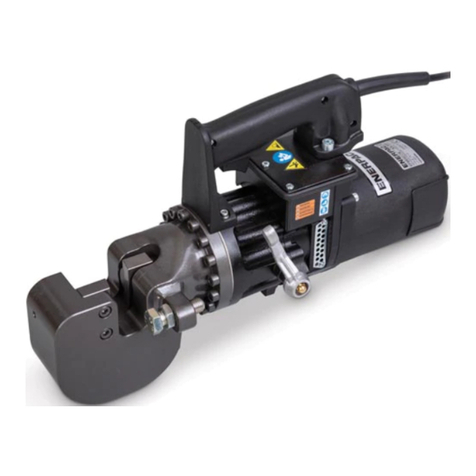
Enerpac EBC20B User manual

1
L4316 Rev. D 05/21 EN
1.0 SAFETY
1.1 Introduction
Read all instructions carefully. Follow all recommended
safety precautions to avoid personal injury as well
as damage to the product and/or damage to other
property. Enerpac cannot be responsible for any
damage or injury from unsafe use, lack of maintenance
or incorrect operation. Do not remove warning labels,
tags, or decals. In the event any questions or concerns
arise, contact Enerpac or a local Enerpac distributor for
clarification.
If you have never been trained on cutting tool safety,
consult your distributor or service center for information
about an Enerpac safety course.
This manual follows a system of safety alert symbols,
signal words and safety messages to warn the user of
specific hazards. Failure to comply with these warnings
could result in death or serious personal injury, as well
as damage to the equipment or other property.
The Safety Alert Symbol appears
throughout this manual. It is used to alert
you to potential physical injury hazards.
Pay close attention to Safety Alert Symbols and obey all
safety messages that follow this symbol to avoid the
possibility of death or serious personal injury.
Safety Alert Symbols are used in conjunction with certain
Signal Words that call attention to safety messages or
property damage messages and designate a degree or
level of hazard seriousness. The Signal Words used in
this manual are DANGER, WARNING, CAUTION and
NOTICE.
NOTICE:
DANGER
Indicates a hazardous situation that,
if not avoided, will result in death or
serious personal injury
NOTICE:
WARNING
Indicates a hazardous situation that,
if not avoided, could result in death
or serious personal injury.
NOTICE:
CAUTION
Indicates a hazardous situation that,
if not avoided, could result in minor
or moderate personal injury.
NOTICE
Indicates information considered
important, but not hazard related
(e.g. messages relating to property
damage). Please note that the Safety
Alert symbol will not be used with this
signal word.
POWERFUL SOLUTIONS. GLOBAL FORCE.
Instruction Sheet
Cordless Bar Cutter
Models EBC20B and EBC20E
INDEX
1.0 SAFETY .............................1
2.0 PRODUCT DATA ......................6
3.0 CONFORMANCE TO NATIONAL AND
INTERNATIONAL STANDARDS ...........8
4.0 DESCRIPTION ........................8
5.0 RECEIVING INSTRUCTIONS .............8
6.0 SET-UP .............................9
7.0 BATTERY ...........................10
8.0 FEATURES AND CONTROLS ...........11
9.0 CUTTER OPERATION .................13
10.0 MAINTENANCE .....................16
11.0 CLEANING THE PISTON AREA .........22
12.0 STORAGE .........................23
13.0 TROUBLESHOOTING ................23

2
• Before reaching inside the cutting area for any reason,
always stop the cutter and remove the battery.
• Keep others clear of the work area while the tool is
in use. Be sure that all personnel not operating the
cutter remain at a safe distance when the cutter is
in operation.
• Stop the cutter if people and/or animals enter the
work area.
• Ensure that the operator is alert, observant of the task
being performed and that the work is being done with
care.
• Do not allow use of the cutter by persons that are
tired, or under the influence of drugs, alcohol or
medication.
• Do not allow children to operate the cutter or to assist
with its use. Keep children out of the work area.
• Place the tool horizontally on a substantial work
surface. The work surface must have a rated weight
capacity that exceeds the weight of the cutter and of
the material being cut.
• Fragments and splinters may be ejected from the
cutter during normal use. The end of the material
being cut may become a projectile as it separates
during cutting. Stay clear of the cutting head and
surrounding area during operation. Always wear face
and eye protection.
• As needed, remove any foreign objects from
the cutting head that could damage the cutter
and/or injure the operator. Before removing any
foreign objects, always stop the cutter and remove
the battery.
• Avoid touching the cutter’s metal surfaces during
operation and after the cutter has been in use. Be
aware of the risk of burns if the cutter becomes hot.
• Do not use the cutter for activities other than those
it was approved and designed to perform. Refer to
Section 9.1 of this manual for additional information
regarding foreseen use.
• Use the cutter’s built-in handles when lifting or
moving the cutter. Use the cutter lifting eye and
appropriately rated lifting equipment if it is necessary
to lift or suspend the tool by mechanical means.
• Do not exceed equipment ratings. Never attempt to
cut an item that is above the maximum allowable
diameter, tensile strength or hardness for your cutter
model. For additional information, refer to Section 2.1
of this manual. Overloading may cause equipment
failure and possible personal injury.
• Do not use the cutter in explosive atmospheres
(for example, in the presence of flammable liquids,
gasses or powders).
• Do not use the cutter on live electric lines, on
pressure vessels or ducts, or on vessels containing
corrosive and/or toxic substances.
• If the cutter malfunctions, stop use immediately.
Check for misaligned or jammed moving parts,
broken components and any other condition that
could make the tool operate incorrectly. Place the
1.2 Hydraulic Cutter Safety Precautions
NOTICE:
WARNING
Failure to observe and comply with the
following precautions and instructions may result in
death or serious personal injury. Property damage
could also occur.
• Read and completely understand the safety
precautions and instructions in this manual. Always
follow all safety precautions and instructions,
including those that are contained within the
procedures of this manual.
• Read this manual before operating the cutter, or
before performing any adjustments, inspections,
maintenance or repairs.
• Follow all instructions and heed all precautions
stated in this manual.
• Keep this manual for future reference in a place that
is accessible to all persons operating or servicing the
cutter.
• Always perform a visual inspection of the cutter
before placing it into operation. If any problems are
found, do not use the tool. Make repairs before using
the cutter.
• Do not use the cutter if it is leaking oil. Do not use the
cutter if damaged, altered or in need of repair.
• Do not remove or disable cutter safety devices.
Before using the cutter, make sure that all the safety
devices (guards, etc.) are in place and in good
condition.
• Do not remove the guards installed on the cutter or
on any accessories. Replace any guards immediately
if they develop faults or become damaged.
• Do not alter the calibration of the safety devices,
such as maximum pressure valves (if equipped).
• Allow only authorized, trained, and experienced
personnel to operate the cutter and supervise its use.
• Ensure that all users are trained and qualified to
operate the cutter. Operators must be aware of
all applicable occupational safety laws and must
operate the cutter in accordance with all such laws.
• Keep the work area clean and well illuminated.
• When operating the cutter, do not wear loose
clothing or jewelry that could get caught up in the
cutter during operation. Tie up long hair.
• Always wear and use appropriate personal protective
equipment (PPE) such as non-skid safety shoes,
hard-hat, hearing protection and face and eye
protection. Use of these and other PPE items (used
as appropriate for conditions) will reduce the chance
of personal injuries. The use of these items may also
be required by local regulations or laws.
• Consult your employer concerning specific safety
requirements and the safety equipment required for
use in your country or region.
• Be certain that the cutter blade safety guard is
installed before starting the cutter. Never operate the
cutter with the safety guard removed, or if the safety
guard is loose or damaged.
3
• Do not use the tool if it cannot be switched on and o
using the trigger. Any tool that cannot be controlled
with the trigger on-o switch is dangerous and must
be repaired.
• Remove the battery from the tool before making
adjustments, before changing accessories or before
performing any maintenance or repairs. These
preventative safety measures reduce the risk of the
tool being operated accidentally.
• Remove all wrenches and adjustment tools (if
present) before switching on the tool. A wrench or
adjustment tool attached to a rotating element of a
power tool can cause personal injury.
• Make sure the cooling vents are unobstructed and
that the cooling surfaces are clean in order to avoid
dangerous overheating.
• The tool is designed for noncontinuous use. Allow
suciently long pauses to allow the oil to cool.
Consult Enerpac if prolonged and/or uninterrupted
use is required.
• Keep the tool away from rain and wet conditions.
Water entering a battery powered tool will increase
the risk of electric shock.
• Do not expose the tool to heat sources in excess of
158°F [70°C] as this could cause irreversible damage
to cable insulation and other electrical components,
possibly leading to a fire.
• Do not service or clean the tool, or replace blades
or guards, while the tool is operating and/or if the
battery is installed.
• Keep the tool out of the reach of children. Do not
allow inexperienced users or users who have not
read the instructions to operate the tool. Power tools
are dangerous in the hands of non-expert users.
• In accordance with the standards indicated and
followed by the manufacturer, the equipment
components that also perform a safety function
(insulators, guards, etc.) must not be repaired, but
must instead be replaced with original spare parts.
• Ensure that the tool is serviced by a qualified
technician using original equipment spare parts. This
will help ensure that the tool remains safe to operate.
1.4 Rechargeable Battery Safety
WARNING
Failure to observe and comply with the
following precautions could result in death or serious
personal injury. Property damage could also occur.
• Do not charge or use the battery in explosive
atmospheres, such as in the presence of flammable
liquids, gases or dust.
• Never force the battery into the tool or the charger.
• Never attempt to open the battery case for any
reason.
• If the battery case is cracked or damaged, do not
insert into tool or charger.
• Do not crush, drop or damage the battery.
• Do not use a battery that has received a sharp blow,
cutter back into operation only after the fault has
been identified and the identified repairs and/or
adjustments have been performed.
• Ensure that any repairs are performed only by
trained, qualified and authorized sta using original
equipment replacement parts. For repair service,
contact the Enerpac authorized service center in
your area.
• Use only original equipment Enerpac parts. Enerpac
parts are designed to fit properly and to withstand
high loads. Non-Enerpac parts may break or cause
the product to malfunction.
• Keep cutting tools clean and replace blades when
they become dull. Suitably maintained cutting tools
with sharp edges are less likely to jam and are easier
to control.
CAUTION
Failure to observe and comply with the
following precautions and instructions could result
in minor or moderate personal injury. Property
damage could also occur.
• To help ensure proper operation and best
performance, use only Enerpac HF hydraulic oil. Use
of any other oil may result in unsafe operation and/or
damage to tool. The Enerpac product warranty may
also be invalidated.
• Keep the tool away from flames and heat. Excessive
heat will soften packings and seals, resulting in
possible hydraulic fluid leaks.
• Protect all hydraulic equipment from weld spatter.
1.3 Cordless Electric Tool Safety Precautions
NOTICE:
WARNING Failure to observe and comply with the
following precautions and instructions may result in
death or serious personal injury. Property damage
could also occur.
• Refer to the separate instruction manual (published
by DeWALT) for detailed battery and charger
safety information, operating instructions and care
information. Observe all warnings and other stated
precautions. Failure to observe these precautions
may lead to fire, electrocution and/or serious
personal injury.
• Always be certain that tool is stopped and battery is
removed before reaching inside the cutting head or
performing any tool cleaning, maintenance or repair
procedures.
• Do not leave the tool unattended in the workplace.
Remove battery and take all reasonable precautions
to avoid unauthorized use.
• Take precautions to ensure that the tool is not
switched on accidentally. Be sure that the on-o
trigger is not depressed when installing the battery,
or when picking up or transporting the tool. Accidents
can occur if power tools are lifted or transported
while the operator’s finger is on the trigger, or if the
battery is installed while the operator’s finger is on
the trigger.

4
Max Diameter Alert:
Cutting diameter must not
exceed 20 mm [0.79 inch].
PPE Alert: Wear personal
protective equipment
(PPE) when using or
servicing equipment
Instruction Manual Alert: Read the
instruction manual before using or servicing
equipment.
1.7 Crush Hazard
DANGER
Cutter will start immediately when
battery is installed on cutter and on-o trigger is
depressed.
DO NOT place hands, fingers or other parts of your
body inside the cutting head unless battery is
removed from cutter. Death or serious personal
injury will result if cutter is started while persons are
working inside the cutting head.
• Never reach into the cutting head while cutter is in
operation.
• Before reaching inside the cutting head for any
reason, always stop the cutter and remove battery.
been dropped, run over, or damaged in any way (e.g.,
pierced with a nail, hit with a hammer, stepped on,
etc.). Damaged batteries should be properly recycled
or disposed of, in accordance with all applicable laws
and regulations in your country or region.
• Do not store or carry the battery so that metal objects
can contact exposed battery terminals.
• Refer to manufacturer’s battery and charger manual
for complete safety precautions, use and disposal
instructions, and transport instructions.
• Use the cutter only with a compatible battery of
original equipment specifications. Use of a non-
compatible battery may result in erratic and/or unsafe
operation.
1.5 Lithium-ion Batteries - Additional Safety
Information
NOTICE:
DANGER
Failure to observe and comply with the
following precautions will result in death or serious
personal injury. Property damage could also occur.
• Do not incinerate the battery even if it is severely
damaged or completely worn out. The battery
can explode in a fire. Toxic fumes and materials are
created when lithium-ion batteries are burned.
• If battery contents come into contact with the
skin, immediately wash area with mild soap and
water. If battery liquid gets into the eye, rinse water
over the open eye for 15 minutes or until irritation
ceases. If medical attention is needed, note that the
battery electrolyte is composed of a mixture of liquid
organic carbonates and lithium salts.
• Contents of opened battery cells may cause
respiratory irritation. Provide fresh air. If symptoms
persist, seek medical attention.
1.6 Safety Symbols (on cutter)
WARNING
Failure to observe and comply with the
safety symbols axed to the cutter housing could
result in death or serious personal injury.
WARNING
Make sure the safety symbols (decals,
labels, etc.) are securely axed to the tool and that
they are legible. If not, obtain replacements from
Enerpac. Refer to tool repair parts sheet for locations
and part numbers. Failure to maintain safety symbols
on tool could result in death or serious personal
injury.
The following safety symbols are axed to the cutter
housing:
Crush hazard: Keep hands, fingers and other
body parts away from the cutting head.
Projectile hazard: Objects may be ejected
from the cutter during operation. Stay clear of
cutting area. Wear eye and face protection.

5
1.8 General Power Tool Safety Warnings
NOTICE:
WARNING Read all safety warnings, instructions,
illustrations and specifications provided with this
power tool. Failure to follow all instructions listed below
may result in electric shock, fire and/or serious injury.
Save all warnings and instructions for future
reference.
The term “power tool” in the warnings refers to your
mains-operated (corded) power tool or battery-operated
(cordless) power tool.
1) Work area safety
a) Keep work area clean and well lit.
Cluttered or dark areas invite accidents.
b) Do not operate power tools in explosive
atmospheres, such as in the presence of
flammable liquids, gases or dust. Power
tools create sparks which may ignite the dust or
fumes.
c) Keep children and bystanders away while
operating a power tool. Distractions can cause
you to lose control.
2) Electrical safety
a) Power tool plugs must match the outlet.
Never modify the plug in any way. Do not use
any adapter plugs with earthed (grounded)
power tools. Unmodified plugs and matching
outlets will reduce risk of electric shock.
b) Avoid body contact with earthed or grounded
surfaces, such as pipes, radiators, ranges
and refrigerators. There is an increased risk
of electric shock if your body is earthed or
grounded.
c) Do not expose power tools to rain or wet
conditions. Water entering a power tool will
increase the risk of electric shock.
d) Do not abuse the cord. Never use the cord
for carrying, pulling or unplugging the power
tool. Keep cord away from heat, oil, sharp
edges or moving parts. Damaged or entangled
cords increase the risk of electric shock.
e) When operating a power tool outdoors, use
an extension cord suitable for outdoor use.
Use of a cord suitable for outdoor use reduces
the risk of electric shock.
f) If operating a power tool in a damp location
is unavoidable, use a residual current device
(RCD) protected supply. Use of an RCD
reduces the risk of electric shock.
3) Personal safety
a) Stay alert, watch what you are doing and
use common sense when operating a power
tool. Do not use a power tool while you are
tired or under the influence of drugs, alcohol
or medication. A moment of inattention while
operating power tools may result in serious
personal injury.
b) Use personal protective equipment. Always
wear eye protection. Protective equipment
such as dust mask, non-skid safety shoes, hard
hat, or hearing protection used for appropriate
conditions will reduce personal injuries.
c) Prevent unintentional starting. Ensure
the switch is in the o-position before
connecting to power source and/or battery
pack, picking up or carrying the tool. Carrying
power tools with your finger on the switch or
energizing power tools that have the switch on
invites accidents.
d) Remove any adjusting key or wrench before
turning the power tool on. A wrench or a key
left attached to a rotating part of the power tool
may result in personal injury.
e) Do not overreach. Keep proper footing and
balance at all times. This enables better control
of the power tool in unexpected situations.
f) Dress properly. Do not wear loose clothing
or jewelry. Keep your hair and clothing away
from moving parts. Loose clothes, jewelry or
long hair can be caught in moving parts.
g) If devices are provided for the connection
of dust extraction and collection facilities,
ensure these are connected and properly
used. Use of dust collection can reduce dust-
related hazards.
h) Do not let familiarity gained from frequent
use of tools allow you to become complacent
and ignore tool safety principles. A careless
action can cause severe injury within a fraction
of a second.
4) Power tool use and care
a) Do not force the power tool. Use the correct
power tool for your application. The correct
power tool will do the job better and safer at the
rate for which it was designed.
b) Do not use the power tool if the switch
does not turn it on and o. Any power tool
that cannot be controlled with the switch is
dangerous and must be repaired.
c) Disconnect the plug from the power
source and/or remove the battery pack,
if detachable, from the power tool before
making any adjustments, changing
accessories, or storing power tools. Such
preventive safety measures reduce the risk of
starting the power tool accidentally.
d) Store idle power tools out of the reach of
children and do not allow persons unfamiliar
with the power tool or these instructions
to operate thepower tool. Power tools are
dangerous in the hands of untrained users.

6
clips, coins, keys, nails, screws or other small
metal objects, that can make a connection
from one terminal to another. Shorting the
BATTERY terminals together may cause burns or
a fire.
d) Under abusive conditions, liquid may be
ejected from the BATTERY; avoid contact. If
contact accidentally occurs, flush with water.
If liquid contacts eyes, additionally seek
medical help. Liquid ejected from the BATTERY
may cause irritation or burns.
e) Do not use a BATTERY pack or tool that is
damaged or modified. Damaged or modified
batteries may exhibit unpredictable behavior
resulting in fire, EXPLOSION or risk of injury.
f) Do not expose a BATTERY pack or tool to fire
or excessive temperature. Exposure to fire or
temperature above 130 °C may cause explosion.
g) Follow all charging instructions and do
not charge the BATTERY pack or tool
outside the temperature range specified in
the instructions. Charging improperly or at
temperatures outside the specified range may
damage the BATTERY and increase the risk of
fire.
6) Service
a) Have your power tool serviced by a
qualified repair person using only identical
replacement parts. This will ensure that the
safety of the power tool is maintained.
b) Never service damaged BATTERY packs.
Service of BATTERY packs should only be
performed by the manufacturer or authorized
service providers.
e) Maintain power tools and accessories. Check
for misalignment or binding of moving parts,
breakage of parts and any other condition
that may aect the power tool’s operation.
If damaged, have the power tool repaired
before use. Many accidents are caused by
poorly maintained power tools.
f) Keep cutting tools sharp and clean. Properly
maintained cutting tools with sharp cutting
edges are less likely to bind and are easier to
control.
g) Use the power tool, accessories and tool bits
etc. in accordance with these instructions,
taking into account the working conditions
and the work to be performed. Use of the
power tool for operations dierent from those
intended could result in a hazardous situation.
h Keep handles and grasping surfaces dry,
clean and free from oil and grease. Slippery
handles and grasping surfaces do not allow
for safe handling and control of the tool in
unexpected situations.
5) BATTERY tool use and care
a) Recharge only with the charger specified by
the manufacturer. A charger that is suitable for
one type of BATTERY pack may create a risk of
fire when used with another BATTERY pack.
b) Use power tools only with specifically
designated BATTERY packs. Use of any other
BATTERY packs may create a risk of injury and
fire.
c) When BATTERY pack is not in use, keep it
away from other metal objects, like paper
2.0 PRODUCT DATA
2.1 Cutter Maximum Capacities
Material to be Cut
Cutter
Model
No.
Material Maximum
Diameter
Material Maximum
Tensile Strength
Material Maximum
Hardness
in mm psi daN/mm2Rockwell C
Round, square or
flat metal bars
EBC20B
EBC20E 0.79 20 94,275 65 43
NOTICE
Material to be cut must not exceed any of the stated maximum limits shown in this table.
Cutter may stall during operation if one or more of the maximum limits is exceeded.
2.2 General Specifications
Cutter
Model
Number
Max. Cutting
Force
Weight
(without battery)
Max. Hydraulic
Operating
Pressure
Ambient
Operating Temp
Hyd.
Pump
Tons kN lb Kg psi bar °F °C Type
EBC20B
EBC20E 21.2 188.3 19.2 8.7 7977 550
- 40
to
+ 122
- 40
to
+ 50
Internal,
Battery
Powered

7
2.4 Battery Specifications
Manufacturer DeWALT Industrial Tool Co.
Region Americas Europe and Asia
Battery Type Lithium-Ion Lithium-Ion
DeWALT Model No. DCB205 DCB184-XJ
Enerpac Part No. B205 B185
Rated Voltage 20 Volts Max. DC 18 Volts DC
Rated Capacity 5.0 Amp Hours 5.0 Amp Hours
Weight 1.4 lb [0.62 Kg] 1.4 lb [0.62 Kg]
Enerpac EBC-Series cutters are designed to operate exclusively with the specified DEWALT ®batteries.
DeWALT ®is a registered trademark of DeWALT Industrial Tool Company (a division of Stanley Black & Decker,
Inc.), 701 East Joppa Road, Towson, MD 21286 USA.
DeWALT ®has not manufactured, licensed, approved, or endorsed the Enerpac EBC Series cutters.
WARNING Use only a genuine DeWALT battery of the stated specifications indicated for your region. Do not
use batteries of dierent brands and/or specifications. Use of incorrect battery may result in improper tool
operation and risk of burns and/or electric shock. Death or serious personal injury could occur.
2.5 Charger Specifications
Manufacturer DeWALT Industrial Tool Co.
Region Americas Europe and Asia
DeWALT Model No. DCB115 DCB115-QW
Enerpac Part No. BC1220B BC1220E
Input Voltage 120 Volts AC, 60Hz 230 Volts AC, 50Hz
Rated Capacity 5.0 Amp Hours 5.0 Amp Hours
Charging Voltage 12-20 Volts DC 12-20 Volts DC
Charging Time 60-90 Minutes 60-90 Minutes
Weight 1.3 lb [0.49 Kg] 1.3 lb [0.49 Kg]
NOTICE
Use only a genuine DeWALT battery charger of the stated specifications indicated for your region.
NOTICE
Refer to the DeWALT battery and charger instruction manuals for complete specifications and additional
information. Battery and charger specifications are subject to change without notice.
2.3 Power and Noise Level Specifications
Cutter
Model
Number
Input
Voltage
(Volts)
Current
Type
Rated Input
Current
(Amps)
Electrical
Power
(Watts)
Insulation
Class
Noise Level (typical)
No Load
LWA
†
No Load
Operator
LpAB
EBC20B
EBC20E 18 - 20 Direct (DC) 46 830 III 93 82
Notes: †Per EN 62841-1 and EN 62841-2-8.
BPer EN 62841-1 and EN ISO 5349.

8
2.6 Dimensions
Dimension in mm
C
A B
A 19.8 504
B 6.9 176
C 13.9 354
Product specifications are subject to change without notice.
3.0 CONFORMANCE TO NATIONAL AND
INTERNATIONAL STANDARDS
Enerpac declares that this product has been
tested and conforms to applicable standards
and is compatible with all CE requirements.
A copy of an EU Declaration of Conformity is
enclosed with each shipment of this product.
4.0 DESCRIPTION
The Enerpac cordless bar cutters, models EBC20B and
EBC20E, are designed to cut round, square or flat metal
bars and other similar items.
These cutters contain two blades, one fixed and one
moving. The moving blade is actuated by a hydraulic
cylinder.
Power is supplied by an 18 or 20 volt lithium-ion battery
(varies by region). The battery powers a DC electric
motor, which drives a small hydraulic gear pump. The
pump provides oil flow to the hydraulic cylinder, which
advances the cylinder piston.
A hydraulic reservoir with built-in rubber diaphragm
provides a constant supply of oil to the pump, regardless
of tool orientation or the amount of piston extension.
A trigger-style on-o switch, mounted on the cutter grip,
starts and stops the electric motor. The trigger must
remain pressed during the cutting process.
An automatic retract feature moves the piston to the
fully retracted “home” position when the piston reaches
its full stroke and the trigger is released.
A built-in blade safety guard provides protection from
splintered material during cutting and helps prevent
contact with the blades.
The rotatable cutting head can be turned 360 degrees,
allowing it to be positioned as needed for added
convenience.
See Figure 1 for a description of cutter major features
and components. Refer to Sections 2.1 through
2.6 of this manual for maximum cutting capacities,
specifications and dimensions.
5.0 RECEIVING INSTRUCTIONS
Visually inspect all components for shipping damage.
Shipping damage is not covered by warranty. If shipping
damage is found, notify carrier at once. The carrier
is responsible for all repair and replacement costs
resulting from damage in shipment.
5.1 Documents and Accessories
The following documents and accessories are included
with the cutter:
• Instruction Sheet
• Declaration of Conformity
• Protective Storage Case
• Allen Wrench – 8 mm
• 2 x Battery 20V-5Ah (Model EBC20B only)
• 2 x Battery 18V-5Ah (Model EBC20E only)
• Charger, 115V (Model EBC20B only)
• Charger, 230V (Model EBC20E only)

9
123 4
6
789
5
13
10
11
12
Figure 1, Features and Components
Key:
1. Cutting Head with Fixed Blade
2. Safety Guard
3. Piston and Moving Blade
4. Hydraulic Cylinder
5. Piston Release Screw
11. Grip/Handle
12. Trigger On-O Switch
13. Storage Case
6. Positioning Handle
7. Lifting Eye
8. Oil Reservoir
9. DC Electric Motor
10. Li-Ion Rechargeable Battery
6.0 SET-UP
6.1 Delivery and Handling
The cutter is housed inside a protective storage case
which contains additional room for two batteries. If
ordered with the cutter, the batteries and battery charger
will be included in a separate package.
NOTICE
Always remove the battery from the cutter
before placing the cutter in the case. Always store the
cutter and batteries inside the case when not in use.
The cutter is designed for handheld operation. During
periods when cutting is not in progress, place the cutter
on a stable and level surface capable of supporting the
combined weight of the cutter and battery. Refer to
Sections 2.2 and 2.4 for weights.
6.2 Before Startup
• Be sure that the shipment includes all components
and that there is no obvious damage.
• Read the following sections of this manual to become
familiar with cutter features and safety devices.
• Fully charge the battery and install it on the tool. Refer
to Section 7.0 for battery information. For charger
operating instructions, refer to the separate battery
and charger manual (published by DeWALT).
NOTICE
Be sure that cutter piston is advanced as far
as possible before removing oil reservoir cap in the
next step. Oil leakage and improper operation may
result if this instruction is not followed.
• Advance the piston as far as possible, remove battery
from cutter and check the cutter hydraulic oil level.
Add oil if oil level is low. Refer to Section 10.5.2 for
detailed instructions.
• Be sure that the piston release screw is fully tightened.
Refer to Section 8.3.
• Before first use, remove air from the cutter hydraulic
system. Refer to procedure in Section 9.3.

10
7.0 BATTERY
7.1 General Information
The cutter is powered by a lithium-ion battery
manufactured by DeWALT. The battery should be fully
charged before the tool is used.
Batteries and chargers are available from Enerpac and
from selected DeWALT distributors and retailers.
To ensure optimum performance and safe operation,
use only the DeWALT batteries and chargers of the
proper specifications. Refer to Sections 2.4 and 2.5 of
this manual for additional information.
NOTICE
A separate battery and charger instruction
manual is published by DeWALT. Refer to this manual for
detailed use and care information and important safety
precautions. Be sure this manual is read and understood
by all persons operating the cutter.
7.2 Battery Charge Indicator
To check the approximate battery charge level, push the
battery test button and observe the green lights. See
Figure 2.
2
1
Three Green Lights: 51 to 100% charge
Two Green Lights: 26 to 50% charge
No Green Lights: Fully discharged
One Green Light: Less than 25% charge
Figure 2, Battery Charge Indicator
Key:
1. Battery Test Button
2. Indicator Lights
Before operating the cutter, always check the charge
level to be certain that you have sucient battery charge
available to complete the cutting operation.
If the battery charge is low, place the battery on the
charger and wait until it is fully charged before reinstalling
it on the cutter.
7.3 Battery Temperature
• If possible, avoid using or storing the battery in
locations where the ambient temperature may reach
or exceed 104ºF [40ºC]. For best service life, store
batteries in a cool, dry location.
• To prevent serious damage to the battery, do not
charge the battery at ambient temperatures of below
40ºF [4.5ºC] or above 104ºF [40ºC].
7.4 Battery Installation and Removal
NOTICE:
WARNING
DO NOT press the on-o trigger while
installing the battery. Serious personal injury could
occur if cutter starts unexpectedly as battery is
being installed.
Refer to Figures 3 and 4.
To install the battery: Place the cutter on a stable work
surface. Align grooves and slide the battery fully onto the
bracket at the bottom of the tool grip. You should hear a
“click” when the battery is fully installed.
To remove the battery: Place the tool on a stable work
surface. While depressing the release button, grasp the
battery firmly and slide it out of the bracket.
1
Figure 3, Battery Release Button (1)
Figure 4, Battery Installation
Three Green Lights: 51 to 100% charge
Two Green Lights: 26 to 50% charge
One Green Light: Less than 25% charge
No Green Lights: Fully discharged

11
8.0 FEATURES AND CONTROLS
8.1 Cutting Head Position
The cutting head can be rotated 360 degrees to aid in
the positioning of the cutting blades and to allow greater
flexibility and safety for the operator.
Adjust the cutting head as described in the following
steps. Refer to Figures 5 and 6.
1. To prevent accidental startup, be sure that battery is
removed from tool.
2. Firmly grasp the grip/handle with one hand.
3. With your other hand, firmly grasp the positioning
handle and rotate the cutting head, twisting it in either
direction, until the desired cutting head position is
achieved.
Always position the cutting head so that the blades are
at a right angle (90 degrees) to the bar or other item
being cut. Refer to Section 9.5 for additional information. 2
1
Figure 5, Cutting Head Rotation
Key:
1. Positioning Handle
2. Grip/Handle
Figure 6, Cutting Head Positions

12
Figure 8, Piston Positions (viewed from top)
Fully Advanced
Fully Retracted (“home” position)
8.3 Piston Release Screw
Before using the cutter, check that the piston release
screw is turned fully clockwise and securely tightened.
Use an 8 mm Allen wrench. See Figure 9.
In the event that the blade becomes stuck during
cutting, loosen the piston release screw one full turn
counterclockwise to manually release the piston. When
the screw is loosened, the piston will retract immediately,
assuming that no dirt or debris is preventing its return.
NOTICE:
CAUTION
To prevent possible oil leakage, do not
loosen the piston release screw more than one full
turn counterclockwise.
NOTICE
Refer to the procedures in Section 11.0 of this
manual if the blade is not returning due to accumulated
dirt or debris.
Tighten the piston release screw to resume normal
operation. Note that the piston will not advance when
the screw is loosened.
Be advised that the piston release screw is intended
for occasional use only. If the piston repeatedly fails to
retract automatically after it is fully extended, have the
tool inspected by an Enerpac Authorized Service Center.
8.2 Trigger On-O Switch
NOTICE:
WARNING To prevent serious personal injury, be
certain that hands, fingers and other body parts are
away from the cutting area before depressing the
cutter trigger.
A trigger mounted in the cutter grip controls cutter
operation. Pressing the trigger automatically starts the
cutter electric motor. See Figure 7.
• Press and hold the trigger to advance the piston
and slide the moving blade forward. After the cut is
completed, release the trigger to retract the piston.
• Release the trigger at any time to stop the piston and
moving blade. Be advised that there may be a brief
delay until the piston comes to a complete stop.
• Retraction of the piston can occur only after the piston
has been fully advanced. If the trigger is released
before the piston is fully advanced, the piston will stop
and remain stopped.
Figure 7, Trigger On-O Switch
Fully Advanced
Fully Retracted (“home” position)

13
1
2
Figure 9, Piston Release Screw
8.4 Cutter Blade Safety Guard
The cutter is equipped with a blade safety guard to
prevent contact with the upper part of the fixed blade.
See Figure 10.
The blade safety guard is manufactured of stainless
steel and is secured to the cutting head with one screw.
NOTICE:
WARNING
Failure to observe and comply with the
following precautions and instructions could result
in death or serious personal injury.
• Never operate the cutter with safety guard
removed.
• Be certain that safety guard is in good condition
and tightly secured. Replace guard if worn, damaged
or missing. Tighten or replace screws if loose or
missing.
• Always reinstall safety guard after performing any
adjustments, maintenance or repairs.
Figure 10, Blade Safety Guard (1)
1
9.0 CUTTER OPERATION
9.1 Foreseen Use and Residual Risks
NOTICE:
WARNING Failure to observe and comply with the
instructions and precautions contained in the
following paragraphs could result in death or serious
personal injury.
1. The cutter must be used only to cut round, square or
flat metal bars and other similar items. Material
diameter, tensile strength and hardness must not
exceed the maximum allowable values shown in
Section 2.1 of this manual.
2. The cutter must be operated only with a battery
specified for use with the cutter. Refer to Section 2.4
of this manual.
3. Operators must observe the instructions in this
manual in order to minimize the risk of accidents.
In particular, operators must pay attention when
working in conditions that could cause:
• Possible burns from overheated metal parts.
• Injury due to incorrect positioning or inadequate lifting
or moving.
• Injury caused by splinters discharged from the bar or
other workpiece.
NOTICE:
WARNING People remaining in the vicinity of the
cutter while it is working are subject to the risk of
flying debris (dangerous objects, etc. ). Serious
personal injury could result.
4. Mechanical vibrations transmitted to the hands and
arms can pose a risk to the health and safety of
workers. The user and/or employer is responsible for
assessing the risk generated by mechanical vibrations
from the cutter, and minimizing the possibility of
injury.
5. Incorrect use:
• The cutter must not be used for purposes other than
indicated in this manual.
• The cutter must not be used in areas subject to the
risk of explosion.
9.2 Operating Precautions
NOTICE:
WARNING
Failure to observe the following
precautions and instructions could result in death or
serious personal injury.
• Keep fingers, hands and other body parts clear of
the cutting head. Do not reach into the cutting area
during cutter operation.
• Do not attempt to reposition the item being cut
while the cutter is in operation. If repositioning is
required, stop the cutter and loosen the piston
release screw to retract the piston. Then, tighten the
piston release screw and repeat the cutting process.
• Dangerous projectiles could occur at any time
during cutting. Always wear face and eye protection.
Keep persons away from cutting area.
Key:
1. Normal Operation (tighten)
2. Piston Release (loosen)

14
• Cutter surfaces can become very hot. To prevent
burns, avoid contact with cutter components and
wear appropriate personal protective equipment.
•
Refer to additional safety precautions in Section 1.0
of this manual before using the cutter or performing
any maintenance or repair activities.
9.3 Trapped Air Removal
Before placing a new cutter into operation, cycle the
piston several times without load to remove any trapped
air in the hydraulic circuit.
Air is completely purged when the piston advances and
retracts smoothly in both directions, from fully advanced
to fully retracted.
This procedure should be performed after the oil in the
cutter is changed, and after any maintenance or repair
activity in which the oil is drained and replaced.
9.4 Locating and Positioning the Cutter
• Before inserting material to be cut inside the cutting
head, be certain that the cutter is placed on a solid
and stable work surface of sucient weight rating
capacity. Refer to Section 2.2 for cutter weight.
• Position the cutter as needed using the positioning
handle.
• If it is desired to lift or support the cutter by mechanical
means, use only the lifting eye mounted at the top of
the cutter housing.
• See Figure 11.
Key:
1. Positioning Handle
2. Lifting Eye
1
2
Figure 11, Positioning Handle and Lifting Eye
NOTICE:
WARNING
Because the cutter components are very
heavy, there is a risk of cuts, crushing or broken bones. To
avoid accidents, use care when working with the cutter.
Serious personal injury may result if the cutter is not
properly supported and handled in an appropriate way.
9.5 Positioning Material Inside the Cutting Head
Be sure that the piston and moving blade are located in
the fully retracted “home” position before placing any
material inside the cutting head. See Figure 8.
Position the material to be cut between the cutter
blades, so that it is perpendicular to the piston axis, as
shown in Figure 12. This will provide the best quality cut
while placing the least amount of load on the cutter.
Adjust the support bolt as needed. The head of the
support bolt should just touch the surface of the material
to be cut, when the item is positioned against the fixed
blade of the cutter.
After adjusting the support bolt, be sure that the support
bolt retaining nut is snug tight against the support
bolt mounting ear. This will help prevent support bolt
movement during cutting.
NOTICE
Be certain that the hardness, tensile strength
and diameter of the material do not exceed any of the
stated maximum limits. Refer to Section 2.1 of this
manual for additional information. Failure to observe this
instruction may result in poor cutting performance
and/or damage to the cutter.
9.6 Cutting Procedure (typical)
1. Be certain that a battery is installed on the cutter and
that the battery has sucient charge to complete the
cutting operation.
2. Be sure that the piston is in the “home” (fully retracted)
position. See Figure 8.
3. Be sure that the piston release screw is turned fully
clockwise. See Figure 9.
4. Place the material to be cut between the fixed and
moving blades. Refer to instructions in Section 9.5 for
additional information.
NOTICE
Position the item to be cut so that it is as
perpendicular as possible to the blades, as described in
Section 9.5. Positioning the material at an angle will
side-load the piston. Jamming and/or damage to the
cutter may result.
5. Be certain that hands, fingers or other body parts are
not inside the cutting head.
6. Press and hold the on-o trigger to start the motor
and begin cutting.
7. After cutting is completed, wait until the piston
reaches the end of its stroke and then release the
on-o trigger. Verify that the moving blade reverses
direction and moves fully into the “home” (fully
retracted) position.

15
Figure 13, Material Being Cut (typical - top view)
9.7 Additional Information
• Stop using the cutter when a noticeable decrease in
motor performance occurs. Continuing to operate
the cutter with a low battery charge increases the
possibility that the cutter may stop as a cutting
procedure is in progress.
• The cutter is designed with an electronic protection
system that will protect the battery against
overloading, overheating or deep discharge.
• The cutter will automatically turn o if the electronic
protection system engages. If this occurs, place
the lithium-ion battery on the charger until it is fully
charged.
• Refer to the battery and charger manual (published by
DeWALT ) for complete battery charging instructions
and important safety precautions.
Figure 12, Positioning Material Inside the Cutting Head
90°
90°

16
10.0 MAINTENANCE
10.1 Preparation for Maintenance
All cutter maintenance procedures must be performed
under the following conditions:
• Material must be removed from the cutting head.
• The battery must be removed from the cutter.
• The cutter must be given time to cool to prevent burns.
• Procedures must be performed in a suitable work
environment in accordance with all current safety
regulations and/or laws in your country or region.
• The cutter must be cleaned thoroughly before
maintenance procedures are performed.
• Suitable personal protective equipment (PPE) must be
used and/or worn while performing any work.
NOTICE:
WARNING
The cutter must sometimes be
operated in order to complete a maintenance or
repair procedure being performed, or to prepare it
for a procedure that is about to be performed.
However, to prevent startup while persons are
working on the cutter, always remove the battery
from the cutter before beginning any procedure
steps that require use of tools and/or physical
contact with the cutter. Failure to observe this
precaution may result in death or serious personal
injury.
NOTICE:
WARNING
Ensure that cutter blade safety guard
has been correctly reinstalled before placing the
cutter back into service after maintenance
procedures are completed. Failure to reinstall this
guard could result in serious personal injury.
10.2 Periodic Maintenance Chart
Refer to the Periodic Maintenance Chart (Table 1) for a
list of various routine checks and procedures.
10.3 Cleaning
• Clean the cutter using a dry cloth or compressed air.
For plastic surfaces, use a cloth slightly dampened
with water.
NOTICE:
CAUTION
To prevent possible injury, always wear
safety glasses or face mask when using compressed
air.
• Be sure there are no traces of oil, grease or corrosive
substances on the tool, especially on the grips.
• Use a damp cloth and soapy water to clean plastic
components.
• Do not use gasoline or thinner to clean the tool.
10.4 Fasteners
Periodically check all screws, nuts and other fasteners
for proper tightness. Tighten any loose fasteners.
Replace any worn or damaged fasteners. This should
be performed periodically or every day in the event of
frequent or prolonged cutter operation.
NOTICE
Failure to check and tighten fasteners as
required may result in serious damage to the cutter.
10.5 Cutter Hydraulic System
The cutter contains a small hydraulic pump and oil
reservoir with rubber diaphragm. The oil level must be
periodically checked and additional oil must be added if
the oil level is low. In addition, the oil must be completely
changed at the specified interval. Refer to the Periodic
Maintenance Chart (Table 1).
Table 1, Periodic Maintenance Chart
Time Interval Maintenance Operation Method Maint. Level
Every 8 hours of
operation:
Check the cutter for loose,
damaged or worn parts.
Check for oil leaks. Tighten,
replace or repair as required.
Visual Operator
Check the tightening
torque of screws and bolts.
Replace any missing screws
or bolts.
(Refer to instructions in Section 10.4) Operator
Check fixed and moving
blades for wear.
(Refer to instructions in Section 10.6.1) Operator
Every 1600 hours
of operation:
Change the hydraulic oil. (Refer to instructions in Section 10.5.3) Service Center
As required: Clean the cutter piston. (Refer to instructions in Section 11.0) Operator
Replace fixed and moving
blades.
(Refer to instructions in Section 10.6.2
and 10.6.3)
Operator

17
10.5.1 Hydraulic System Maintenance Precautions
NOTICE:
WARNING
Always remove battery from cutter before performing
hydraulic system maintenance. Failure to observe
this precaution could result in accidental startup
while maintenance procedures are being performed.
Serious personal injury and damage to cutter may
result.
Wait for cutter to cool before performing hydraulic
system maintenance. Hot oil can cause burns.
Be sure that oil reservoir cap is securely tightened
after checking oil level or changing the oil. Leaking
oil can cause short circuits, fire and explosions.
Additional Precautions:
• Do not check oil level or change the oil in dusty areas.
• Be sure that all tools (wrench, screwdriver, etc.) used
to perform maintenance procedures are clean.
• When adding oil and performing oil changes, take every
precaution to prevent impurities from contaminating
the oil or entering the cutter. Impurities can cause
permanent damage to the hydraulic components.
• The hydraulic reservoir contains a diaphragm that
slightly pressurizes the oil. Some oil spillage may occur
when checking the oil level or when changing the oil.
Wear and/or use appropriate personal protective
equipment (PPE) to prevent exposure to hydraulic oil.
• Use only new Enerpac HF hydraulic oil poured from a
clean container. Use of other oil brands and/or used
oil may damage the cutter and may void the Enerpac
product warranty.
10.5.2 Checking Oil Level and Adding Oil
NOTICE
The reservoir contains a flexible rubber
diaphragm that slightly pressurizes the oil. To help
prevent excessive oil leakage when the reservoir cap is
removed, be certain that the piston is advanced until
there is a gap of about 1/8 inch [3-4 mm] between the
fixed and moving blades (as described in step 1) before
loosening the cap.
The gap between the blades should not be less than
1/8 inch [3-4 mm]. A smaller gap may result in the piston
retracting unexpectedly while the oil level is being
checked.
Refer to Figure 14 and Figures 15A through 15C during
the following steps:
1. Operate the cutter and advance the piston until
there is a 1/8-inch [3-4 mm] gap between the fixed
and moving blades (until just before the piston
automatically returns).
2. Remove the battery to prevent accidental motor
startup during the following steps.
3. Place the cutter on a stable and level work surface,
with the oil reservoir cap facing straight up. Note that
the cap does not face straight up when the tool is
laid on a flat surface, so positioning aids are required.
Place a pan or suitable container under the cutter to
catch any spilled oil.
NOTICE
The oil reservoir cap is located just below the
on-o trigger when the cutter is positioned in the
inverted (upside-down) position. Be certain to remove
only this cap in the next step. DO NOT remove the relief
valve by mistake. See Figure 14.
Figure 14, Oil Drain/Fill Cap
(cutter shown in inverted position)
1
2
Key:
1. Oil Reservoir Cap
2. Relief Valve
(DO NOT remove)
4. To prevent contamination, remove any built-up dust
and dirt from the oil reservoir cap and surrounding
area.
NOTICE
A small amount of hydraulic oil may leak from
the drain/fill hole when cap is loosened in the next step.
Be prepared to catch this oil in a pan or with a clean rag.
Dispose of spilled oil in accordance with all applicable
laws and regulations.
5. Slowly loosen the oil reservoir cap while watching for
oil flow:
• If oil starts flowing from the oil drain/fill hole as the
cap is loosened, the reservoir is full. Tighten the cap
immediately. To avoid excessive oil spillage, do not
continue loosening the cap if oil flow occurs. Skip
steps 6 through 8 and go on to step 9.
• If no oil flow occurs when the cap is loosened, fully
loosen and remove the cap. Then, check oil level and
add oil (if needed) as described in steps 6 through 8.
6. Check the oil level in the drain/fill hole. Oil level will be
up to the top of the hole when reservoir is full.
7. If oil level is low, slowly add new Enerpac HF oil
through the oil drain/fill hole, until the oil level is up to
the top of the hole.
8. Remove any residue or metal particles from the oil
reservoir cap (it is magnetic).

18
Figure 15, Hydraulic System Maintenance
Figure 15B, Oil Reservoir Cap - Loosen (1) and
Tighten (2)
2
1
1
Figure 15C, Adding Oil to Reservoir Fill Hole (1)
1
2
3
4
Figure 15D, Diaphragm Cover (1), Diaphragm (2),
Diaphragm Opening (3) and Oil Reservoir (4)
Figure 15A, Oil Reservoir Cap (1)
1
9. Install and securely tighten the oil reservoir cap.
10. Using a clean rag, wipe the cutter housing, grip and
motor so that these surfaces are free of oil residue.
11. Insert the battery. Cycle the piston several times to
test for proper operation before placing the cutter
back into service.
10.5.3 Changing the Oil
NOTICE
The oil change procedure is very detailed and
will take a considerable amount of time. It should only be
performed by a trained technician at an Enerpac
authorized service center. Failure to properly perform the
procedure may result in incomplete filling of the cutter oil
reservoir, which could lead to cavitation, air entrainment,
reduced performance, and pump damage.
Change the oil in the cutter reservoir as described in
the following steps. Refer to Figure 14 and Figures 15A
through 15D:
1. Fill a clean oil dispenser with new Enerpac HF oil. Put
the dispenser aside for later use.
2. Procure a thick, soft metal bar (about 1/4 inch
[6.4 mm] minimum thickness). Put the bar aside for
later use.

19
(as needed) to keep the reservoir filled. Failure to
keep reservoir full may result in cavitation and
pump failure. Pump is primed when piston starts
extending.
NOTICE
During priming, the oil may become entrained
with air and may develop a foamy appearance. This is
normal.
17. Continue pressing and releasing the trigger in short
bursts as the piston extends. During this process,
do not add oil, but verify that the pump has ample
oil supply. Continue until piston is extended to
approximately half stroke.
NOTICE
During the following steps, refer to Figure 9 for
piston release screw details.
18. While covering the diaphragm opening with a
rubber-gloved hand, retract the piston gently by
slowly loosening the piston release screw.
19. Tighten the piston release screw.
20. Place the soft metal bar (refer to step 2) into the
cutting head.
21. Press and release the trigger in short bursts until
the piston is extended as far as possible, but before
it makes a full cut and retracts. The moving blade
will become lodged in the bar, preventing the
piston from retracting. This procedure is necessary
because the cutter mechanism alone may fail to
hold the piston in the partially extended position as
oil is being added in the following steps.
NOTICE
If you cut completely through the bar, try again,
cutting as far as you can without making a full cut.
22. Remove the battery to prevent accidental motor
startup during the following steps.
23. Add oil through the diaphragm opening until the
diaphragm opening is nearly full.
24. Slowly install the diaphragm in the diaphragm
opening. This should result in some oil leakage from
around the diaphragm.
25. Install and securely tighten the diaphragm cover.
26. Loosen the piston release screw to retract the
piston. If piston is stuck, use the bar to manually
push the piston back until it retracts.
27. Remove the soft metal bar from the cutting head.
Do not discard the bar. It will be used again later in
this procedure.
28. Tighten the piston release screw.
29. Insert the battery.
NOTICE:
WARNING To avoid serious personal injury, stay
clear of cutting head and blades during the following
procedures.
30. Start the cutter and cycle the piston through several
advance and return strokes. Ensure that piston is
fully retracted when done.
NOTICE
The bar selected should be easy to cut, but not
brittle. The bar material must be soft enough so that the
bar will not break into two pieces before it is fully cut.
Later in this procedure, the bar will be partially cut so
that it becomes lodged in between the jaws of the cutter
without being cut through completely, as the piston is
extended to slightly less than maximum travel.
3. Ensure the piston is completely retracted.
4. Remove the battery to prevent accidental motor
startup during the following steps.
5. Place the cutter in the horizontal position, on a stable
and level work surface, with the oil reservoir cap
facing up. It is not critical that it face straight up, as
in the oil check procedure. Place a pan or suitable
container under the cutter to catch any spilled oil.
6. To prevent contamination, remove any built-up dust
and dirt from the oil reservoir cap, diaphragm cover,
and surrounding area.
NOTICE
A small amount of hydraulic oil leakage may
occur when the diaphragm cover is removed in the next
step. Be prepared to catch this oil in a pan or with a
clean rag. Dispose of spilled oil in accordance with all
applicable laws and regulations.
7. Loosen and remove the oil reservoir cap.
8. Using an adjustable face spanner wrench, loosen and
remove the diaphragm cover.
9. Remove the diaphragm from the diaphragm opening.
10. Completely drain all old oil from the cutter, turning
it upside down and using a suitable oil extraction
system (used oil extraction pump) if necessary, so
that no oil remains in the cutter reservoir.
NOTICE
Dispose of all used oil in accordance with all
applicable regulations and laws.
11. After all oil is evacuated, position the cutter with the
diaphragm opening facing up.
12. Install the oil reservoir cap.
NOTICE
Use only new Enerpac HF oil in the following
step. Use of other oils may damage the cutter and may
invalidate the Enerpac product warranty.
13. Using the oil dispenser prepared in step 1, slowly
add new Enerpac HF oil through the diaphragm
opening until oil level is up near the top.
NOTICE:
WARNING To avoid serious personal injury, stay
clear of cutting head and blades during the following
procedures. Wear rubber gloves to prevent contact
with oil. Wear eye and face protection to avoid injury
due to splashing oil.
14. Insert the battery.
15. Cover the diaphragm opening with a rubber-gloved
hand to help prevent oil splashing.
16. Prime the pump by pressing and releasing the
trigger in short bursts. During this process, check
the oil level in the diaphragm opening and add oil

20
31. Be sure cutter is positioned so that the oil reservoir
cap is facing straight up. Do not operate cutter for
several hours (preferably overnight) to allow any
remaining air to separate from the oil.
32. Place the soft metal bar (refer to step 2) into the
cutting head.
33. Press and release the trigger in short bursts until
the piston is extended as far as possible, but before
it makes a full cut and retracts. The moving blade
will become lodged in the bar, preventing the
piston from retracting. This procedure is necessary
because the cutter mechanism alone may fail to
hold the piston in the partially extended position as
oil level is being checked in step 35.
NOTICE
If you cut completely through the bar, try
again, cutting as far as you can without making a full cut.
34. Remove the battery to prevent accidental motor
startup during the following steps.
35. Loosen and remove the oil reservoir cap. Recheck
the oil level in the oil drain/fill hole. If oil level has
dropped, add additional Enerpac HF oil until the oil
level is up to the top of the hole.
36. Install and securely tighten the oil reservoir cap.
37. Loosen the piston release screw to retract the
piston. If the piston is stuck, use the bar to manually
push the piston back until it retracts.
38. Using a clean rag, wipe the cutter housing, grip and
motor so that surfaces are free of oil residue.
39. Insert the battery. Cycle the piston several times to
test for proper operation before placing the cutter
back into service.
10.6 Cutter Blade Replacement
NOTICE:
WARNING
•
Always remove battery from cutter before
beginning blade replacement procedures. Failure to
observe this precaution could result in accidental
startup during blade replacement. Serious personal
injury could result.
• Use extreme caution when removing and installing
blades. Blades may be sharp even when worn. To
avoid hand injury, wear appropriate personal
protective equipment (PPE) and avoid contact with
blade cutting edges.
10.6.1 Blade Wear
The use of worn blades decreases the eectiveness of
the cutter and can also side load the cylinder, resulting
in possible damage to the tool. Motor overheating can
also occur.
Replace blades immediately if they are worn and/or
damaged or if there has been a noticeable decrease in
cutting performance.
NOTICE
Blades are not sharpenable and must be
replaced when worn. To help ensure optimum cutting
performance, replace both the fixed blade and the
moving blade at the same time.
This manual suits for next models
1
Table of contents
Other Enerpac Cutter manuals

Enerpac
Enerpac EFBE5017 User manual

Enerpac
Enerpac EBH35 User manual

Enerpac
Enerpac ECSE300 User manual

Enerpac
Enerpac ECCE32 User manual

Enerpac
Enerpac EBE22 User manual

Enerpac
Enerpac EFBE7015 User manual

Enerpac
Enerpac EBE26 User manual

Enerpac
Enerpac EDCH130 User manual

Enerpac
Enerpac NC-1319 User manual

Enerpac
Enerpac ECCE26 User manual
Popular Cutter manuals by other brands

DIY CREW
DIY CREW PAPER ROLL CUTTER Assembly instruction

Husqvarna
Husqvarna K 3000 Cut-n-Break Operator's manual

Cricut Expression
Cricut Expression 24" Personal Electronic Cutter user manual

Erbauer
Erbauer ERB337TCB Original instructions

Alpha tools
Alpha tools A-MF 1300 Original operating instructions

Globe
Globe GFP500 instruction manual