Enersound T?500 User manual
1
USERMANUAL
Passionforinnovation
ModelT‐500
Multi‐ChannelFMTransmitter

2
T‐500TableofContents_________________________________________
AboutthisManual…………………………………………………………………..3
PackageContents……………………………………………………………….…..3
SystemOverview……………………………………………………………….…...3
Quickreference:Controls,displaysandconnectors……….……….4‐5
FrontPanel…………………………………………………………………………..4
RearPanel………………………………………………………………….…………5
Set‐upInstructions………………………………………………………………….6‐11
GeneralSet‐UpInstructions…………………………………………………6‐8
ApplicationNotes………………………………………………………………..9‐11
a)Fordirectlanguageinterpretation……………………………….9‐10
b)Forlanguageinterpretationwithinterpreterconsole….10‐11
MenuSettingInstructions……………………………………………………….11‐13
SafetyInformation………………………………………………..………………..13‐14
TroubleShooting…………………………………..………………………………..14‐15
FCC&ICStatements……………………………………………………………….16
WarrantyStatement……………………………………………………………….17
OptionalAccessories……………………………………………………….……...18
FrequencyChart……………………………………………………………………..18
TechnicalSpecifications…………………………………………………………..19

3
AboutthisManual
ReadthisusermanualcarefullybeforeinstallingandoperatingyourT‐500FM
transmitter.Usetheproductonlyasdescribedtoavoidaccidentalinjury,damageor
hearingimpairment.Also,readsafetywarningscarefully.Keepthismanualfor
futurereference.Ifyougivethisproducttosomeoneelse,remembertoincludethis
manual.
PackageContents
(1)T‐500FMmulti‐channeltransmitter(72‐76MHz)
(1)ANT‐500helicalantenna
(1)PS‐500powersupplywithACcord
(1)Usermanual
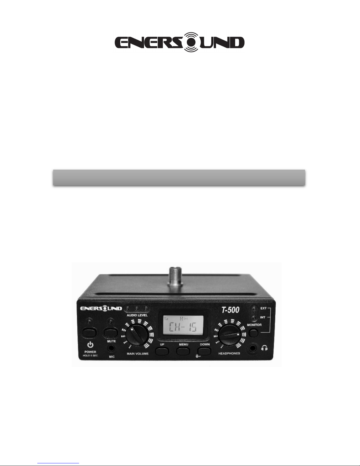
SystemOverview
ThankyouforchoosingtheEnersoundT‐500FMmultichanneltransmitter.This
professionaltransmitterisdesignedforassistivelisteningandlanguage
interpretation.Itwirelesslybroadcastsaspeaker’svoice,musicoranyaudiosignal
upto1000ft.(305m).TheaudiencecanusetheoptionalR‐120FMmultichannel
receiveroranyothercompatibleFMreceiveroperatingonthe72‐76MHzfrequency
topickupthebroadcast.TheT‐500transmitterfeatures3mainaudioinputsthat
allowthedirectconnectionofvirtuallyanyanalogaudiosource,includinga3.5mm
jackforheadsetmicrophones,anXLR&¼inchcombinationjackwithaselectorfor
dynamicmicrophones,condensermicrophonesorline‐levelsignals,andaRCAline
auxiliaryinput.Italsohasarecordingoutputanda3.5mmmonitorheadphonejack.
Forlanguageinterpretation,ithasauniqueintegratedinterpretermonitorfunction.
Thisfeatureallowsinterpreterstoselectanexternalincomingaudiosourceand
utilizeaheadsetwithmicrophonetolistentothesourcelanguagewithouttheneed
ofaninterpreterconsoleorexternalheadphoneamplifier.Throughthe
headphones’volumecontrol,interpreterscansetthedesiredincomingaudiolevel
andthe[MUTE]buttonallowsthemtomomentarilysilencetheirmicrophonefor
coughingorsneezing.Formoreadvancedinterpretingfunctions,itcanalsobe
utilizedwiththeEnersoundIC‐12multi‐channelinterpreterconsoleorwithany
otherinterpretationplatformwithanalogaudiooutputs.
ItsLCDdisplayallowstoeasilyprogramthevarioususefulfunctions,suchastest
tone,RFpowerlevel,displaymode(frequenciesorchannelnumbers),andchannel
lock.
4
QuickReference:Controls,DisplaysandConnectors
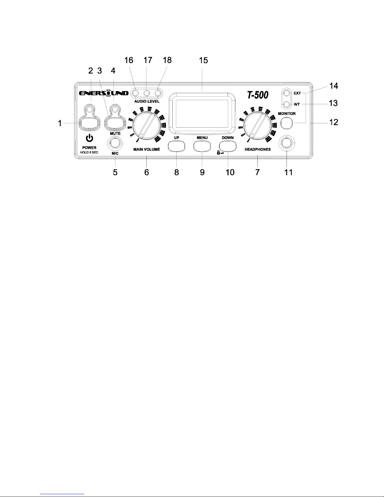
Frontpanel
(1)POWERbutton
:
Press&holdfor5secondstoturnon/offdevice.
(2)Powerindicator
(3)Frontmicrophonemutebutton:Presstomute/unmutefrontmicrophone.
(4)Muteindicatorlight
(5)Micinput,3.5mmjack
(6)Mainvolumecontrol:Adjustsaudiooutputvolume.
(7)Headphonesvolumecontrol
(8)Upbutton:Changeschannel/frequencyup.Duringsettingmode,pressto
modifyselection.
(9)Menubutton:Press&holdfor6secondstoaccesssettingmenu.
(10)Down&lockbutton:Changeschannel/frequencydown.Press&holdfor5
secondstolock/unlockchannel/frequency.Duringsettingmode,pressto
modifyselection.
(11)Headphonesoutput,3.5mmjack
(12)Internal/externalmonitorsourceselectionswitch:SettoEXTforlanguage
interpretationapplicationstomonitoranexternalaudiosource(speechtobe
translated).SettoINTtomonitorthebroadcastedaudio.
(13)Internalselectionindicator
(14)Externalselectionindicator
(15)LCDscreen
(16)(17)Audiolevelindicators
(18)Audiopeakindicator
5
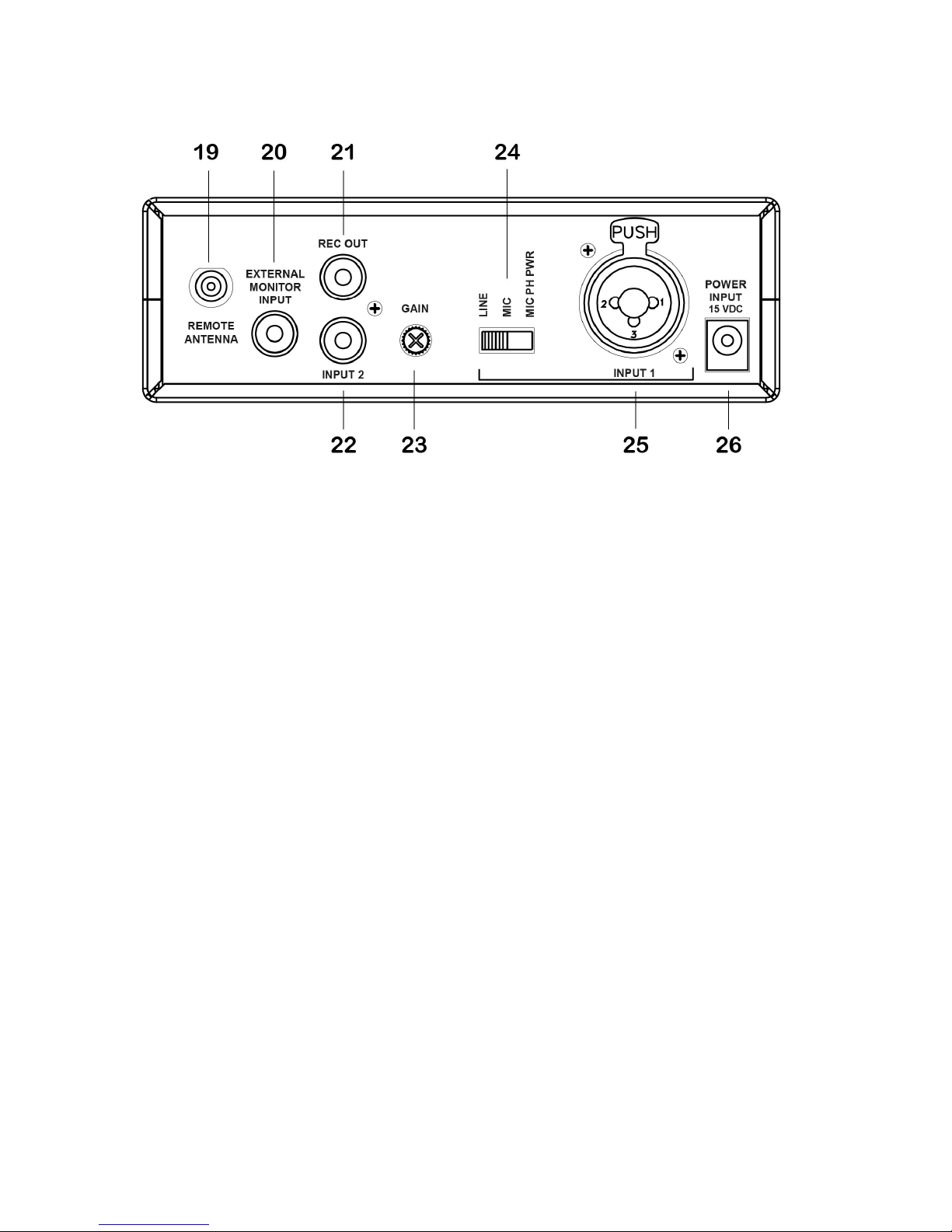
Rearpanel
(19)Remoteantennaconnector
Usedwhentopmountedantennaisnotconvenient,forexamplewhenrack
mounting.UseonlyONEantennaconnectoratatime.
(20)ExternalmonitorInput
Usedinlanguageinterpretationapplications.Theaudiosourcetobetranslated
shouldbeconnectedheresotheinterpretercanlistentothesourcelanguage.
ThissignalwillNOTbebroadcastedtoFMreceivers.
(21)Recordingoutput
ThisRCAjackcontainsamixofInput1,Input2andfront3.5mmmicrophone.
(22)Input2,RCAjack
Connects unbalanced audio signals to be broadcasted.
(23)Gain
AdjustsInput1,Input2andfrontmicgainlevel.
(24)Input1modeselector
Selectslinelevel,microphonelevel,ormicrophonewith12Vphantompowerfor
condensermics.
(25)Input1
Acceptsbalancedorunbalancedconnectionofamicrophoneorlinelevelinput.This
combinationjackacceptseitherXLRor¼”plugs.
(26)Powersupplyjack
UsedwiththeincludedPS‐50015Vpowersupply.
6
Set‐upInstructions
GeneralSet‐upInstructions:
Unpackthetransmitter
Removeouterpackagingandplasticcover.Inspectforphysicaldamageand
immediatelyreportanyissues.
Positiontheunit
Positionthetransmitterneartheaudiosource(soundsystem,mixer,
interpreterdesk,etc.),awayfrommetallicobjectsthatmightinterferewiththe
antenna.
Connecttheantenna
Fortabletopuse,screwintheantennaconnectorontothetransmittertop
antennaconnector.Alternatively,anoptionalremoteantennacanbeused.
Donotusetwoantennasatthesametime.
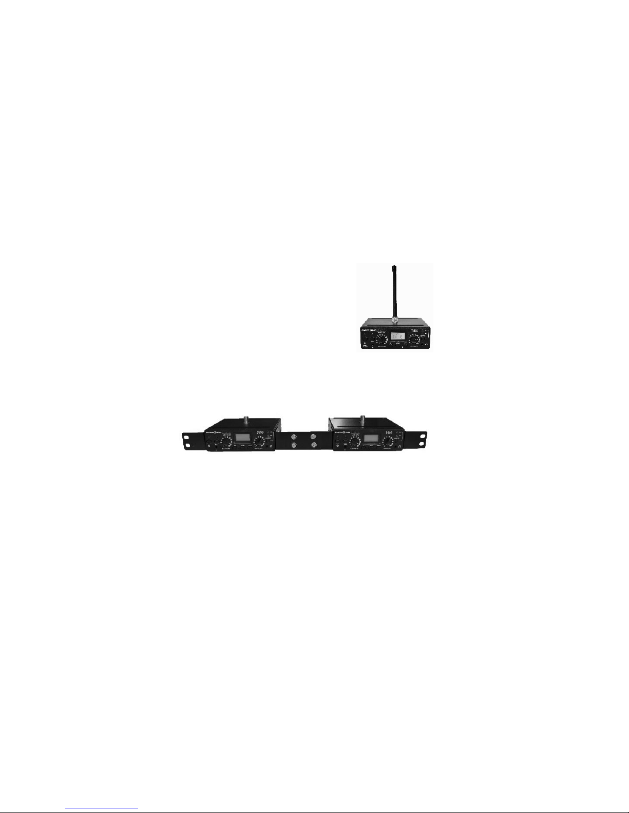
Rackmounttheunit(optional)
Thetransmittercanberackmounted,ifnecessary,ina19’’rackusingthe
optionalrackmountkits:single‐unitRM‐501ordouble‐unitRM‐502.
DualrackmountRM‐502for2T‐500transmitters
NOTE:Ifrackmounting,donotusethetopantennaconnector;youwillneedtouse
therearconnectionantennawitha90degreeadapterAD‐590orusetheoptional
rack‐mountantennakitRAK‐500availableforpurchase.
Ifneeded,youmayalsousearemoteantennaANT‐501.
OnlyuseoriginalEnersoundantennas.CheckwithyourauthorizedEnersounddealer
orvisitwww.enersound.comtoviewavailableaccessories.
PowertheUnit
Plugthepowersupplyintothepowerconnectorontherearpanel,thenconnect
thepowersupplyintoanoutlet.OnlyusetheEnersoundapprovedpower
supply.(ThePS‐500isanautoswitchingpowersupplythatcanworkwith
voltagesbetween100and240V,50/60Hz.)
Pressandholdthe[POWER]buttonfor5secondstoturnontheunit.

7
SelectChannel
Selectthedesiredchannelusingthe[UP]or[DOWN]buttonsonthefrontpanel.
Iftheunitislocked,unlockitbypressingandholdingthe[DOWN]buttonfor5
seconds.
Dependingonthedisplaymode,thescreenwillshoweitherthechannel
number(channelmode)orthefrequency(frequencymode).
Ifnecessary,afterselectingthedesiredchannel,youcanlockitbypressingand
holdingthe[DOWN]buttonfor5seconds.
Note:MakesuretheFMreceiversaretunedtothesamefrequencyastheT‐
500transmitter.IfyouareusingEnersoundR‐120receivers,thechannelswill
correspondtothechannelsontheT500transmitter.Ifyouareusingcompatible
receiversofotherbrands,frequenciesmaydiffer.Consequently,we
recommendsettingtheEnersoundT‐500transmittertoFrequencyDisplay
mode.
TosetthetransmitteronFrequencyDisplaymode,pressandholdthe[MENU]
buttonfor6secondstoaccesstheSettingmenu.Seepage12formoredetails.
EnersoundFrequencyChart
CH 1 72.1 MHz CH 7 72.3 MHz CH 13 75.4 MHz
CH 2 72.5 MHz CH 8 72.7 MHz CH 14 75.8 MHz
CH 3 72.9 MHz CH 9 75.5 MHz CH 15 72.8 MHz
CH 4 75.7 MHz CH 10 75.9 MHz CH 16 72.4 MHz
CH 5 74.7 MHz CH 11 72.2 MHz CH 17 75.6 MHz
CH 6 75.3 MHz CH 12 72.6 MHz
ConnectAudioInputs
TheT‐500hasseveralaudioinputs:
RearPanel:
Input1:ForbalancedorunbalancedconnectionsusingeitheranXLRor1/4”
phonoconnector.Idealforconnectingaudiomixers,dynamicmicrophones
or12Vcondensermicrophones.
PlugyourbalancedorunbalancedaudiosourceintoInput1.Usethe
followingdiagram.
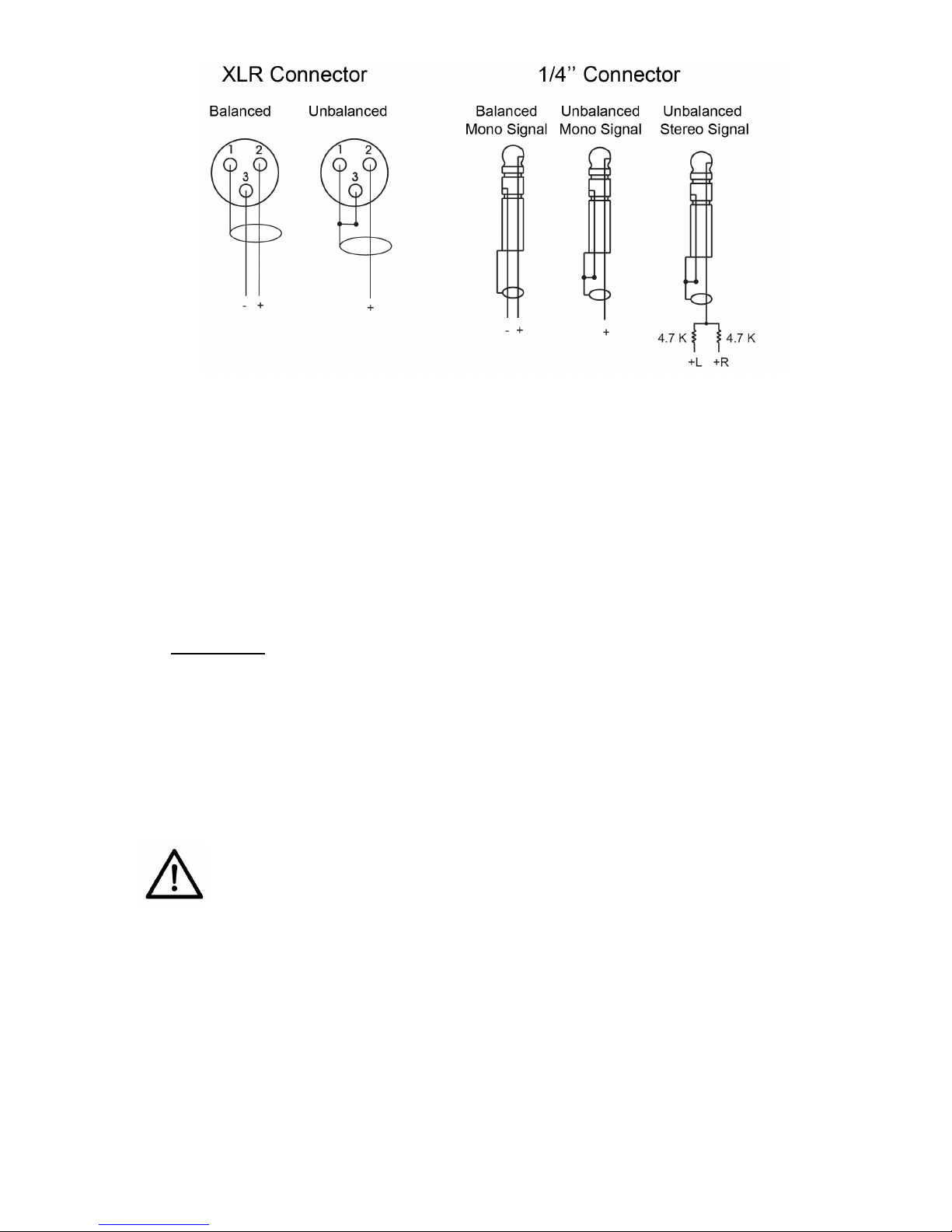
8
Note:Toconnectstereosignalsuseasimpleresistivemixerasshownabove
utilizingtwo4.7KΩresistorsavailableatalocalelectroniccomponentsstore.
Input2:AnRCAauxiliarylinelevelinput.
ExternalMonitorInput:AnRCAlinelevelinputforsimultaneous
interpretationapplicationsthatallowstheinterpretertomonitorthesource
language.Thisaudiosignalwillonlybeheardontheinterpreter’s
headphonesconnectedtotheheadphonejackonthefrontpanelwith
monitorselectorsetonEXT(External).
FrontPanel:
3.5mmmicrophoneInput:Idealforheadbandandheadsetmicrophones
with3.5mmconnectorssuchasEnersoundMIC‐200,MIC‐300,LAV‐100
andinterpreterheadsets.
Connectthedesiredaudiosource(s)tooneormoreaudioinputconnections.Ifusing
input1,selecttheappropriateaudiosetting(line,MICorcondenserMICwith15V
phantompower).
Warning:70voltoranyotherspeakersignalscannotbeconnectedto
theT‐500transmitter.Thismaycausedamagetoyoursystem.
Forusageindirectlanguageinterpretationseeexplanationbelow.
SettheVolume
ListenwithanFMreceiversuchasEnersoundR‐120orothercompatiblereceiver
tunedinthesamefrequencyorchannelandadjustthetransmitter’smainvolume
controllocatedinthefrontpaneltothedesiredlevel.
Ifnecessary,adjustthegaincontrolonthetransmitter’srearpanel.Ifunsure,turn
thegaincontrolclockwisetothemaximumleveloralittlebitless.

9
ApplicationNotes:
a) Directlanguageinterpretation:Incaseswhereone‐wayinterpretationis
required(sourcelanguageintotargetlanguageONLY),youmaytake
advantageoftheT‐500transmitter’sinternal,integratedmonitoring
function.Forexample,inahouseofworshipwherethepreacherspeaksin
EnglishandpartofthecongregationonlyunderstandsSpanish.The
congregationhasapassiverolelisteningtothepreacher’ssermonthrough
theinterpreter’svoice.Uptosixtransmitterscansimultaneouslybeused
inthesameroomtobroadcastuptosixdifferentlanguages.
Inthissituation,werecommendusingeither,aheadbandmicrophoneand
aheadphonefortheinterpreter,oracombinedinterpreterheadsetwith
microphone.
Ineithercase:
Connectthe3.5mmmicrophoneplugontothe3.5mmfrontmicrophone
inputonthetransmitter.
Connectthe3.5mminterpreterheadphoneplugontothe3.5mmfront
headphonesjack.
Ifavailable,connecttheaudiofeedfromthePAsystem(soundsystem)
ontotheRCAexternalmonitorinputlocatedonthetransmitterrearpanel.
Caution:Lowerthemonitorvolumecounterclockwisetotheminimum
levelbeforeconnectingtheaudiofeedtoavoidphysicalhearingdamage.
SetthemonitorsourceselectionswitchintheEXT(External)position.This
switchislocatedonthefrontpanel.
Setthedesiredmonitorvolumetoacomfortablelevelfortheinterpreter.
Setthemainvolumelevel:Speakthroughtheinterpreter’smicrophoneand
listenwithanFMreceiver,suchasEnersoundR‐120orothercompatible
receivertunedinthesamefrequencyorchannel,andadjustthe
transmitter’smainvolumecontrollocatedinthefrontpaneltothedesired
level.
Note:Seewiringdiagramonthenextpage.

10
DirectLanguageInterpretationAudioWiringDiagram:
b) Languageinterpretationwithexternalinterpreterconsole:Incaseswheretwo‐
wayinterpretationisrequired(interpretationfromsourcelanguageintotarget
languageandvice‐versa),externalinterpretingconsolesmaybeneeded.For
example,abilingualormultilingualconferencewherethefloorlanguagechanges
duetopanelistsspeakingdifferentlanguagesortheaudienceinteractingwith
panelistsorpresenterduringquestionandanswersessions.Inthesecases,itis
recommendedtoassignachanneltoeachlanguage.Seebelowanexampleusing
theT‐500transmitterwithEnersoundIC‐12interpreterconsolesforthreeforeign
languages,plusmainlanguage.
Note:Seewiringdiagramonthenextpage.

11
LanguageInterpretationwithExternalInterpreterConsole:WiringDiagram:
MenuSettingInstructions:
Press&holdthe[MENU]buttonfor6secondstoaccesstheMenu.TheLCD
displaywillstartblinkingandthefirstoptionTONEwillbeshown.Tonavigate
throughdifferentmenuoptions,pressthe[MENU]button.
TestTone:WhenTONEisblinking,youcanturnthetoneONorOFFbypressing
the[UP]/[DOWN]buttons.WhenTONEisactivated(ON),thetransmitter
broadcastsatesttonetohelptestreceiverswhennoaudiosourceisavailable.
Aftertestingprocedure,thetoneshouldbedeactivated(OFF).

12
Toexitthemenu,waitfor10secondsandtheLCDscreenwillstopblinking.Youcan
alsoexitthemenubypressingthe[MENU]buttonseveraltimestonavigatethrough
theoptionsuntilyoureachEXITandpress[MENU]onemoretime.
RFPower:WhileinMenu,pressthe[MENU}buttontonavigatethroughtheoptions
untilyoureachPOWER.WhenPOWERisblinking,pressthe[UP]/[DOWN]buttons
tochangethesettingstoLOWorHIGH.TheleveloftransmittedRFpowerneeded
dependsonyourapplication.Ifyouareoperatingseveraltransmittersinthesame
room,itisrecommendedtosetthetransmittersoutputpowertoLOW(L)toreduce
thepossibilityofinterference.Toexitthemenuwaitfor10seconds.
Channel/FrequencyMode:
Youcanchoosethescreentoshoweitherchannelnumbersorfrequencies.Ifyou
areusingEnersoundR‐120receiversorothercompatibleEnersoundreceivers,the
receiverchannelswillcorrespondtotheT‐500transmitterchannels.Ifyouareusing
compatiblereceiversofotherbrands,frequenciesmaydiffer.Consequently,when
usingreceiversfromothermanufacturers,werecommendsettingtheEnersoundT‐
500transmittertoFrequencyDisplaymode.
WhileinMenu,pressthe[MENU}buttontonavigatethroughtheoptionsuntilyou
reachCHANNEL/FREQ.WhenCHANNELorFREQisblinking,pressthe[UP]/[DOWN]
buttonstochangethesettingstoChannelDisplayMode(CHANNEL)orFrequency
DisplayMode(FREQ).Toexitthemenuwaitfor10seconds.
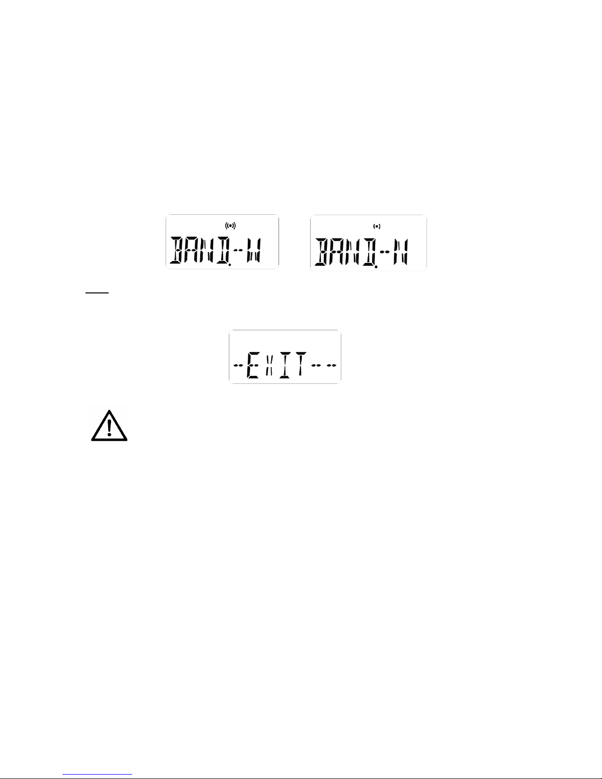
FMDeviation:ThisoptionallowsyoutoselecttheFMtransmitter’sfrequency
deviationbetween+/‐75KHz(W)and+/‐25KHz(N).
WhileinMenu,pressthe[MENU}buttontonavigatethroughtheoptionsuntilyou
reachBAND.WhenBANDisblinking,pressthe[UP]/[DOWN]buttonstochangethe
settingstowide‐band+/‐75KHz(W)ornarrow‐band+/‐25KHz(N).Toexitthemenu
waitfor10seconds.
13
Note:IfyouareusingEnersoundR‐120FMreceivers,choosethe+/‐ 75KHz(W)
option.Mostreceiversofotherbrandsalsoworkon+/‐75KHz.IfyouareusingFM
receiversofotherbrandscheckthereceivers’specsforFMdeviationorcontactthe
manufacturer.
Caution!IfyouareusingareceiverwithFMdeviation+/‐25KHzwithatransmitter
setto+/‐75KHz,youmayexperienceovermodulation,loudvolumeanddistortion.
Incontrast,ifyouareusingareceiverwithFMdeviation+/‐75KHzwithatransmitter
setto+/‐25KHz,youmayexperiencelowaudiovolumeonthereceivers.
Exit:WhileinMenu,pressthe[MENU}buttontonavigatethroughtheoptionsuntil
youreachthefifthoptionEXITandpressthe[MENU]buttononemoretimetoexit
themenu.
SafetyInformation:
HAZARD!PacemakerSafety
Beforeusingthistransmitterand/orreceiverswithapacemakeroranother
medicaldevice,consultyourphysicianorthemanufacturerofyourpacemaker
oranothermedicaldevice.
Ifyouhaveapacemakeroranothermedicaldevice,makesurethatyouare
usingthistransmitterand/orreceiversinaccordancewithsafetyguidelines
establishedbyyourphysicianorthepacemakermanufacturer.
WARNING!DamagetoyourHealth
Usingearphonesorheadphonesataloudvolumeoroveraprolongedperiodof
timecanleadtopermanenthearingdamage.Toprotectyourhearingand
others:
a) Turndownthevolumebeforeputtingontheearphonesorheadphones.
b) Adjustthevolumeattheminimumcomfortablelevel.
c) Iffeedback(asquealingorhowlingnoise)occurs,turndownthe
headphonevolume,andmovethemicrophoneawayfromthereceiver’s
headphones.

14
OtherSafetyConsiderations
Donotleavethedeviceinplaceswithhightemperaturesorhighhumidity.
Donothandlethepowercordwithwethands.
Keepthisdeviceawayfromfireandheatsources.
Keepthisproduct,accessoriesanditspackagingoutofthereachofchildren.
Plasticbags,packingmaterial,electricalcordsandotheraccessoriesmaycause
choking,suffocationand/orelectrocution!
Donotopentheunit.Therearenouserserviceablepartsinside.
Reducethevolumetoitslowestsettingbeforeuse.
Toclean,besuretofirstswitchoffandunplugtheunitfromthepoweroutlet,
thenwipewithadrycloth.Whenextremelydirty,useasoftclothdampenedin
neutraldetergent.Neverusebenzene,thinnerorchemically‐treatedtowels,
whichmaydamagetheproduct’sfinish.
Troubleshooting
Thetransmitterwillnotpower.
VerifythatthePS‐500powersupplyisconnectedtoaworkingpower
sourceandtothetransmitter.
Makesureyouarepressingandholdingthe[POWER]buttonfor5seconds.
Thereisnoaudioonthetransmitter’sheadphonesoutput.
Ifyouareusingthemonitorheadphonesforlanguageinterpretation,make
surethemonitorselectorissettoEXT(Externalaudio).
Verifythattheexternalaudiosignalisconnectedtotheexternalaudio
inputjack.
Verifythatthereisasignalcomingfromyouraudiosource.
Ifyouareusingtheheadphonestomonitorthebroadcastedaudio,make
surethemonitorselectorisintheINT(Internal)position.
Thereisnoaudioortheaudioislowonthereceivers.
Makesurethatthemainvolumeisturnedupandthatyouraudiosourceis
properlyconnected.IfusingInput1,themodeselectorswitchshouldbein
thecorrectposition.Forexample:ifyouareusingtheoutputofamixer,
theswitchshouldbeintheLINEposition.Ifusingadynamicmicrophone,
theswitchshouldbeinMICandifusinga12Vcondensermicrophone,the
switchshouldbeinMICPH‐PWR.
Iftheaudiolevelisstilllow,makesurethatthegainknobontherearpanel
isturnedup.
Ifusingthefrontmicrophonejack,makesurethatthemutefunctionisoff
andthatyouareusingacompatiblemicrophoneinworkingcondition.

15
Thereisnoiseordistortionintheaudio.
Verifyiftheaudioinputlevelistoohighthatoverloadstheinput.Adjust
thegainifnecessary.Ifusinginput1,makesureyouareusingthecorrect
modeselectorswitch.
Checktoseeifthereisnoiseorgroundloopsintheaudiosource.
Ifusingreceiversofotherbrands,makesurethefrequencydeviationBAND
settingonthetransmitteriscompatiblewiththereceivers(N:25KHzorW:
75KHz).PleaserefertoFMDeviationaboveunderMenuSetting
Instructions.
Receiverscannotpickupthesignal.
Makesurethatthetransmitterandthereceiversareturnedon.
Checktomakesurethereceiversandthetransmitterareusingthesame
frequency.Ifusinganotherbrandofreceiver,checkthefrequencychart
correspondingtothereceivers’channelsandthefrequencyonboth
receiversandtransmittermustmatch;channelnumbersmaynotnecessary
bethesame.
Ensuretheantennaonthetransmitterhasbeenproperlyconnected.
Thereisinsufficientrange.
Verifythatyourreceiversareworkingproperly.
Makesuretheantennaisthecorrectoneforyourunitandisadequately
attachedtoeitherthetopoftheT‐500transmitterortothebackofthe
unitifyouareusingaremoteantenna.Neverusetwoantennasatthesame
time.
Ifusingaremoteantenna,keepcoaxialcablefromtransmittertoantenna
asshortaspossible.
Makesurethetransmittingantennaisorientedvertically.
Theantennashouldbeplacedashighaspossibleandfreeofobstacles.
Avoidplacingitinsidemetalenclosures.Avoidobstaclesbetweenthe
listeningareaandtheantennathatmayaffectthesignalstrength,like
partitions,metalobjects,densematerials,studs,pipes,heatingorACducts,
metalgridsorconcrete.
Setthetransmittertohighpower.
Tryusingadifferentchannel/frequencysinceastronginterferingsignal
mayexist.

16
FCCStatement
IntheUS,theFCClimitstheuseofthisdevicetoassistivelisteningandsimultaneous
interpretation.Thistransmittercannotbeusedinallcountries.Checkwithyour
government’sradioregulationsfor72‐76MHzoperation.
Anychangesormodificationsnotexpresslyapprovedbythepartyresponsiblefor
compliancecouldvoidtheuser'sauthoritytooperatetheequipment.
Thisdevicecomplieswithpart15oftheFCCRules.Operationissubjecttothe
followingtwoconditions:
(1)thisdevicemaynotcauseharmfulinterference,and
(2)thisdevicemustacceptanyinterferencereceived,includinginterferencethat
maycauseundesiredoperation.
ICStatement
ThisdevicecomplieswithIndustryCanadalicense‐exemptRSSstandard(s).
Operationissubjecttothefollowingtwoconditions:
(1)thisdevicemaynotcauseinterference,and
(2)thisdevicemustacceptanyinterference,includinginterferencethatmaycause
undesiredoperationofthedevice.
Thisradiotransmitter(T‐500)hasbeenapprovedbyIndustryCanadatooperate
withtheantennatypeslistedbelowwiththemaximumpermissiblegainand
requiredantennaimpedanceforeachantennatypeindicated.Antennatypesnot
includedinthislist,havingagaingreaterthanthemaximumgainindicatedforthat
type,arestrictlyprohibitedforusewiththisdevice.
ThedeviceisincompliancewithRFfieldstrengthlimits;userscanobtainCanadian
informationonRFexposureandcompliance.
LeprésentappareilestconformeauxCNRd'IndustrieCanadaapplicablesaux
appareilsradioexemptsdelicence.L'exploitationestautoriséeauxdeuxconditions
suivantes:
(1)l'appareilnedoitpasproduiredebrouillage,et
(2)l'utilisateurdel'appareildoitacceptertoutbrouillageradioélectriquesubi,même
silebrouillageestsusceptibled'encompromettrelefonctionnement
Leprésentémetteurradio(T‐500)aétéapprouvéparIndustrieCanadapour
fonctionneraveclestypesd'antenneénumérésci‐dessousetayantungain
admisiblemaximaletl'impédancerequisepourchaquetyped'antenne.Lestypes
d'antennenoninclusdanscetteliste,oudontlegainestsupérieuraugainmaximal
indiqué,sontstrictementinterditspourl'exploitationdel'émetteur.
LeprésentappareilestconformeAprèsexamendecematérielauxconformitéaux
limitesDASet/ouauxlimitesd’intensitédechampRF,lesutilisateurspeuventsur
l’expositionauxradiofréquencesetlaconformitéandcomplianced’acquérirles
informationscorrespondantes

17
LimitedWarrantyStatement
EnersoundwarrantstheT‐500motherboardtobefreefromdefectsin
workmanshipandmaterialundernormaluseandconditionsfortheusefullifetime
oftheproductfromdateofpurchasefromanauthorizeddealer.AllotherT‐500
partsincludingconnectors,screenandmovingparts,arewarrantedforoneyear
fromthedateofpurchase.Thiswarrantyisonlyavailabletotheoriginalend
purchaseroftheproductandcannotbetransferred.Iftheproductisdeterminedto
bedefective,Enersoundwillrepairorreplaceit,atitsdiscretion,atnocharge.
Customermustpayforshipping.Thiswarrantyisvoidifdamageoccurredbecause
ofmisuseoriftheproducthasbeenrepairedormodifiedbyanyoneotherthana
factory‐authorizedservicetechnician.Warrantydoesnotcovernormalwearand
tearontheproductoranyotherphysicaldamageunlessthedamagewastheresult
ofamanufacturingdefect.
Enersoundhasnocontrolovertheconditionsunderwhichthisproductisused.
Therefore,thecompanydisclaimsallwarrantiesnotsetforthabove,bothexpress
andimplied,withrespecttotheT‐500transmitter,includingbutnotlimitedtoany
impliedwarrantyofmerchantabilityorfitnessforaparticularpurpose.Enersound
productsmanufacturer,distributorsand/ordealersshallnotbeliabletoanyperson
orentityforanymedicalexpensesoranydirect,incidentalorconsequential
damagescausedbyanyuse,defect,failureormalfunctionoftheproduct,whether
aclaimforsuchdamagesisbaseduponwarranty,contract,tortorotherwise.The
soleremedyforanydefect,failureormalfunctionoftheproductisreplacementof
theproduct.NopersonhasanyauthoritytobindEnersoundtoanyrepresentation
orwarrantywithrespecttotheEnersoundT‐500transmitter.Thiswarrantygives
youspecificlegalrights,andyoumayalsohaveotherrightswhichvaryfromstate
tostate.Somestatesdonotallowlimitationsonhowlonganimpliedwarrantylasts,
andtheexclusionorlimitationofincidentalorconsequentialdamages,sotheabove
limitationmaynotapplytoyou.Thiswarrantyappliestoproductssoldonlywithin
theUnitedStatesofAmericaanddoesnotcoverproductssoldASISorWITHALL
FAULTS.ForproductssoldoutsidetheU.S.,pleaseconsultwithyourlocaldealer
aboutthetermsandconditionsapplicableinyourcountry.Proofofpurchaseinthe
formofabillofsale,invoicenumberorreceiptedinvoice,whichisevidencethatthe
unitiswithinthewarrantyperiod,mustbepresentedtoobtainwarrantyservice.If
youexperienceanyissueswithyourT‐500transmitter,sendanemailto
support@enersound.comwithyourname,address,phonenumberandacomplete
descriptionoftheproblem.Wewillrespondtoyouassoonaspossibleandifitis
necessarytoreturntheproductforservice,yourCustomerServiceRepresentative
willgiveyouaReturnAuthorizationNumber(RAN)andshippinginstructions.For
moreinformation,visitwww.enersound.com.Youmayalsocall1‐305‐731‐2416or
ourtoll‐freenumber1‐800‐644‐5090withintheU.S.

18
T‐500OptionalAccessories
Topurchaseaccessories,contactyourlocaldealer.
Ifyouareunabletofindadealerinyourarea,contactusformoreinformation:
Tollfree:1‐800‐644‐5090
International:+1‐305‐731‐2416
www.enersound.com
EnersoundFrequencyChart
CH 1 72.1 MHz CH 7 72.3 MHz CH 13 75.4 MHz
CH 2 72.5 MHz CH 8 72.7 MHz CH 14 75.8 MHz
CH 3 72.9 MHz CH 9 75.5 MHz CH 15 72.8 MHz
CH 4 75.7 MHz CH 10 75.9 MHz CH 16 72.4 MHz
CH 5 74.7 MHz CH 11 72.2 MHz CH 17 75.6 MHz
CH 6 75.3 MHz CH 12 72.6 MHz
ANT‐500Replacementrubberhelicalantenna
ANT‐501RemoteAntennawith50'coaxcable
PS‐500ReplacementPowerSupply
RM‐501SingleRackMountKittomountoneT‐500transmitteronastandard19”rack
RM‐502DualRackMountKittomounttwoT‐500transmittersonastandard19”rack
RAK‐500
RackMountAntennaKit.Includes: 90degreeadapter,femaletofemalerack
mountantennaconnector,2feetcableassembly
AD‐59090‐DegreeAntennaAdapter
CON‐558MMaleAntennaConnectorforRG58CoaxCable
CON‐558FFemaleAntennaConnectorforRG58CoaxCable
COV‐500Top/BottomMetalEnclosureCover(NoAntennaHole)forT‐500

19
Wereservetherighttomaketechnicalanddesignmodificationstothetransmitterwithoutnotice.
©2015Enersound.Allrightsreserved.
Specifications: Enersound T-500 FM Transmitter
RF
Operating Frequency 72.1-75.9MHz
Number of Channels 17 Selectable
Frequency Deviation Selectable, Wide: +/- 75kHz or Narrow: +/- 25 kHz (Maximum Deviation)
Frequency Accuracy +/- 0.005% stability from 0~+50 degree C
Transmitter Stability +/- 20ppm
Output Power Hi: 80,000uV/m at 3meter, Low: 40,000uV/m at 3meter
Antenna Rubber ducky antenna with 50 ohm impedance or optional remote antenna
Antenna Connector Modified TNC
Compliance FCC part15, Industry Canada
AUDIO
Frequency Response 100Hz ~15KHz (+/- 3db)
Signal to Noise Ratio 70db
System Distortion < 2% (THD) at 80% deviation.
Audio Input 1
3-Pin XLR and ¼” (TRS) combination jack for MIC or LINE level
Balanced or unbalanced. Nominal input level 0/56dbu (0.77V/1.3mV)
(line/mic)
Phantom Power:12VDC PIN 2&3 on XLR or Tip and Ring on ¼” TRS Jack
Audio Input 2 RCA Jack, unbalanced Line Level -10dBu nominal, 100k ohms.
External Monitor In. RCA Jack, unbalanced, Line Level -10dBu nominal, 100k ohms.
REC Output RCA Jack, unbalance output, Line Level -10dBu nominal, 10 ohms.
MIC Input Front panel: 3.5mm 1/8’’ TRS jack, supplies +DC on tip for electret mics.
Audio Processing Built-in signal compression 2:1.
Headphone Out. Front panel: 3.5mm stereo TRS jack adjustable output level,
Max Power 61mW @8ohm, Impedance: 4~16ohm.
POWER
Power Supply Type In Line, UL listed
Power Supply In. 100~240VAC, 50-60Hz
Power Supply Out. 15VDC, 1A
Power Supply
Connector Output Connector: .02 in.(5.0 mm) OD, .01 in.(2.5mm) ID, barrel type
ENVIROM.
Temp. Operation -5℃(23F) to + 40℃(104F)
Temp. Storage -20℃(-4F) to + 60℃(140F)
Humidity 0~95% Relative Humidity
PHYSICAL
Dimensions
(DxWxH) Without top antenna connector: 5” x 5.5” x 1.75” (127 x 140 x 45 mm)
With top antenna connector: 5” x 5.5” x 2.36” (127 x 140 x 60 mm)
Color Black
Unit Weight 1.2 lbs. (0.54 Kg)
Power Supply
Weight 0.5 lbs. (0.22 Kg) with AC cord
Shipping Weight 2.2 lbs. (1.1 Kg)
Rack Mounting One (1.5) rack space height, 1/2 rack space wide, One or Two transmitters
can be mounted in 1.5 rack space, Option rack mount (RM-501 or RM-502)

20
EnersoundContactInformation:
Tollfree:1‐800‐644‐5090
International:+1‐305‐731‐2416
www.enersound.com
Other manuals for T?500
1
Table of contents
Other Enersound Transmitter manuals


