Enersound T-588 User manual

USER MANUAL
Passion for innovation
Model T-588
2-Watt MONO/ STEREO FM TRANSMITTER
88.1-107.9 MHz
United States version (Certified under FCC Part 73 regulations)
Canadian version (Certified under Industry Canada BETS 6 & RSS-123 regulations)


3
T-588 Table of Contents_________________________________________
About this Manual ………………………………………………………………….. 4
Package Contents ……………………………………………………………….….. 4
System Overview ……………………………………………………………….…... 4
Quick reference: Controls, displays and connectors ……….………. 5 - 6
Front Panel ………………………………………………………………………….. 5
Rear Panel ………………………………………………………………….………… 6
General Set-Up Instructions ………………….………………………………… 7 - 10
Menu Setting Instructions ………………………………………………………. 10-12
Safety Information ………………………………………………..……………….. 12-13
Trouble Shooting …………………………………..……………………………….. 13-14
FCC & IC Statements/ ISEDC Warning ………………………………………. 15-16
Warranty Statement ………………………………………………………………. 17
Optional Accessories ……………………………………………………….……... 18
Technical Specifications ………………………………………………………….. 19

4
About this Manual
Read this user manual carefully before installing and operating your T-588 FM
transmitter. Use the product only as described to avoid accidental injury, damage,
or hearing impairment. Also, read safety warnings carefully. Keep this manual for
future reference. If you give this product to someone else, remember to include
this manual.
Package Contents
(1) T-588 FM Mono/ Stereo FM Transmitter (88.1-107.9 MHz)
(1) ANT-588 telescopic antenna
(1) PS-500 power supply with AC cord
(1) User manual
System Overview
Thank you for choosing the Enersound T-588 FM transmitter. This 2-Watt stereo
transmitter wirelessly broadcasts a speaker’s voice, music, or any audio signal in
the 88.1-107.9 MHz frequency band (US version.) The T-588 transmitter features 3
main audio inputs that allow the direct connection of virtually any analog audio
source, including a 3.5 mm jack for headset microphones, an XLR & ¼ inch
combination jack with a selector for dynamic microphones, condenser
microphones or line-level signals, and RCA stereo auxiliary input. It also has a
recording output and a 3.5 mm monitor headphone jack.
For interpretation or audio description, it has a unique integrated interpreter or
narrator monitor function. This feature allows interpreters/ narrators to select an
external incoming audio source and utilize a headset with microphone to listen to
the source language/ audio without the need of an interpreter console or external
headphone amplifier. Through the headphones’ volume control, interpreters/
narrators can set the desired incoming audio level and the [MUTE] button allows
them to momentarily silence their microphone for coughing or sneezing.
Its LCD display allows to visualize the frequency being broadcast, as well as to
easily program the various useful functions, such as RF power level and
mono/stereo transmission.
For use in the USA, please contact your local FCC office for information regarding
permit or license that may be needed based on your application.
For use in Canada, please contact your local Industry Canada office for information
regarding permit or license that may be needed based on your application.
For use outside the USA and Canada, please contact your local telecommunications
authority regarding permit or license that may be needed based on your
application.

Quick
Front
(1) P
O
(2) P
o
(3) Fr
o
(4) M
u
(5) M
i
(6) M
a
(7) H
e
(8) U
p
select
(9) M
e
(10)
D
to loc
k
(11)
H
(12)
I
inter
p
sourc
e
(13)
M
(14)
M
(15) L
C
(16) (
1
(18)
A
Reference: C
o
panel
O
WER buo
n
o
wer indicat
o
o
nt microph
o
u
te indicato
r
i
c input, 3.5
m
a
in volume c
e
adphones v
o
p
buon: C
h
ion.
e
nu buon:
P
D
own
&
lock
b
k
/ unlock fre
q
H
eadphones
o
I
nternal/ext
e
p
retaon/ au
e
.Set to INT
t
M
onitor inter
M
onitor exte
r
C
D screen
1
7) Audio le
v
A
udio peak i
n
o
ntrols, Disp
l
n
: Press & hol
o
r
o
ne mute bu
t
r
light
m
m jack
ontrol: Adju
s
o
lume contr
o
h
anges frequ
e
P
ress & hold
b
uon: Cha
n
q
uency. Duri
o
utput, 3.5
m
e
rnal monit
o
u
dio descript
t
o monitor t
h
r
nal source i
n
r
nal source i
n
v
el indicator
s
n
dicator
l
ays and Con
n
d for 5 seco
n
t
ton: Press t
o
s
ts audio out
o
l
e
ncy up. Du
r
for 6 second
n
ges frequen
c
ng seng m
o
m
m jack
o
r source
s
ion applica
h
e broadcast
e
n
dicator
n
dicator
s
n
ectors
n
ds to turn o
n
o
mute/unm
u
p
ut volume.
r
ing seng
m
s to access s
e
c
y down. Pre
o
de, press to
s
elecon s
w
ons to mon
e
d audio.
n
/ off device.
u
te front mi
c
m
ode, press
e
ng menu.
e
ss & hold fo
r
modify sele
c
w
itch: Set t
o
itor an exte
5
rophone.
to modify
r
5 seconds
c
on.
o
EXT for
rnal audio
1
2
5
4
16 17 18 15
12
6 8 9 10 711
3
13
14
AUDIO LEVEL
MAIN VOLUME
UP MENU DOWN
EXT
INT
MONITOR
HEADPHONES
MUTE
MIC
T-588

Rear
p
(19) A
TNC
c
anten
n
(20) E
x
Used
sourc
e
narrat
This si
(21) I
n
Conn
e
broad
c
(22) R
e
This R
C
3.5 m
m
(23) G
Adjus
t
(24) I
n
Select
s
conde
(25) I
n
Accep
t
input.
(26) P
o
Used
w
p
anel
ntenna conn
e
onnector us
e
n
a.
x
ternal moni
t
in language
e
to be transl
a
or can listen
t
gnal will NOT
n
put 2 (STERE
e
cts unbalanc
c
ast in true st
e
cording out
p
C
A jack conta
m
microphon
e
ain
t
s Input 1, Inp
n
put 1 mode
s
s
line level,
m
nser mics.
n
put 1 (MIC/
L
t
s balanced
o
This combin
a
o
wer supply
j
w
ith the inclu
d
e
ctor
e
d to connec
t
or Input
interpretao
n
a
ted or narra
t
t
o the source
be broadcas
t
O AUX IN), L
e
ed stereo a
u
t
ereo mode.
p
ut
ins a mix of I
n
e
input
ut 2 and 3.5
m
s
elector
m
icrophone l
e
L
INE IN)
o
r unbalance
d
a
on jack acc
e
j
ack
ded PS-500 1
5
t the includ
e
n
and audio
t
ed should be
audio.
t
ed to FM rec
e
e
& Right R
C
u
dio signals t
o
n
put 1 (MIC/
L
m
m front mic
e
vel, or micr
o
d
connecon
e
pts either XL
5
V power su
p
e
d telescopin
g
descripon
a
connected h
e
e
ivers.
C
A jacks
o
be broadc
a
L
INE IN), Inpu
t
gain level.
o
phone with
1
of a microp
h
R
or ¼” plugs.
p
ply.
g
antenna o
r
applicaons.
e
re so the int
a
sted. Use th
t
2 (STEREO
A
1
2V phantom
h
one or mon
o
.
6
r
a remote
The audio
e
rpreter or
is input to
A
UX IN) and
power for
o
line level
6
a remote
The audio
e
rpreter or
is input to
UX IN) and
power for
line level
PUSH
2
3
1
AUX IN
STEREO
MIC/LINE IN
MONITOR
IN
REC OUTANTENNA
L
R
GAIN
MIC PH PWR
MIC
LINE
POWER
IUPUT
15V DC
19 20 21
22 23 24 25 26

7
General Set-up Instructions:
Unpack the transmitter.
Remove outer packaging and plastic cover. Inspect for physical damage and
immediately report any issues to Enersound.
Position the unit.
Position the transmitter away from metallic objects that might interfere with
the antenna or any electromagnetic noise sources such as transformers,
motors, dimmers, etc.) This transmitter is designed to be use in a dry
environment, in temperatures ranging from 23F (-5℃) to 104F (40℃).
The antenna should be located as close to the center of the coverage area
as possible, and at a sufficient height to give the transmitted signal an
unobstructed path to every receiving point. Transmitted signal paths will
be weakened by concrete walls, steel beams, dense materials, or metal
objects.
Connect the antenna.
Screw in the included telescoping antenna onto the transmitter antenna
connector located in the rear panel. Alternatively, an optional remote 50-ohm
antenna with TNC connector can be used to increase the range. Make sure the
remote antenna matches the specific frequency in which you intend to
broadcast.
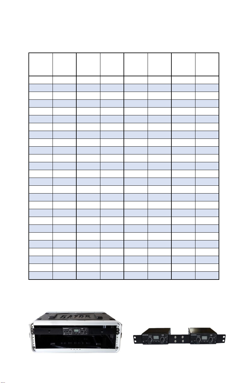
For your convenience, a telescoping antenna
is included with the transmitter for use in
small areas (up to 650’ line of sight with car
radios). The range with this antenna is
significantly shorter than the range with a
remote antenna that is specifically crafted for
the desired frequency. Also, this antenna has
a shorter range on higher frequencies.
When using the telescoping antenna, the rod
length should be adjusted as follows:
1) Choose a free frequency
2) Use the chart (Fig 6.) to note the associated length (ex: 88.5MHz = 44 ½”).
8
3) With the help of a measuring tape or ruler; extend the telescopic antenna in
a manner to obtain the desired length (from base to tip of antenna.)
Fig. 6
Freq
Rod
Freq
Rod
Freq
Rod
Freq
Rod
length
length
length
length
(MHz)
(Inch)
(MHz)
(Inch)
(MHz)
(Inch)
(MHz)
(Inch)
88.1
44 1/2
93.3
37 1/4
98.5
34 1/2
103.7
31 3/4
88.3
44 1/2
93.5
37 1/4
98.7
34 1/2
103.9
31 3/4
88.5
44 1/2
93.7
37 1/4
98.9
34 1/2
104.1
31 1/2
88.7
44 1/2
93.9
37 1/4
99.1
34
104.3
31 1/2
88.9
44 1/2
94.1
36 3/4
99.3
34
104.5
31 1/2
89.1
39 3/4
94.3
36 3/4
99.5
34
104.7
31 1/2
89.3
39 3/4
94.5
36 3/4
99.7
34
104.9
31 1/2
89.5
39 3/4
94.7
36 3/4
99.9
34
105.1
31 1/4
89.7
39 3/4
94.9
36 3/4
100.1
33 3/4
105.3
31 1/4
89.9
39 3/4
95.1
36
100.3
33 3/4
105.5
31 1/4
90.1
39
95.3
36
100.5
33 3/4
105.7
31 1/4
90.3
39
95.5
36
100.7
33 3/4
105.9
31 1/4
90.5
39
95.7
36
100.9
33 3/4
106.1
31
90.7
39
95.9
36
101.1
33 3/4
106.3
31
90.9
39
96.1
35 1/4
101.3
33 3/4
106.5
31
91.1
38 1/2
96.3
35 1/4
101.5
33 3/4
106.7
31
91.3
38 1/2
96.5
35 1/4
101.7
33 3/4
106.9
31
91.5
38 1/2
96.7
35 1/4
101.9
33 3/4
107.1
31
91.7
38 1/2
96.9
35 1/4
102.1
33
107.3
31
91.9
38 1/2
97.1
34 3/4
102.3
33
107.5
31
92.1
37 3/4
97.3
34 3/4
102.5
33
107.7
31
92.3
37 3/4
97.5
34 3/4
102.7
33
107.9
31
92.5
37 3/4
97.7
34 3/4
102.9
33
92.7
37 3/4
97.9
34 3/4
103.1
31 3/4
92.9
37 3/4
98.1
34 1/2
103.3
31 3/4
93.1
37 1/4
98.3
34 1/2
103.5
31 3/4
Rackmount the unit (optional) , not to be used with telescoping antenna.
The transmitter can be rack mounted, if necessary, in a 19’’ rack using the
optional rack mount kits: single-unit RM-501 or double-unit RM-502.

9
Power the Unit
Plug the power supply into the power connector on the rear panel, then
connect the power supply into an outlet. Only use the Enersound approved
power supply. (The PS-500 is an auto switching power supply that can work
with voltages between 100 and 240 V, 50/ 60 Hz.)
Press and hold the [POWER] button for 5 seconds to turn on the unit.
Select Channel
Select the desired channel using the [UP] or [DOWN] buttons on the front
panel. If the unit is locked, unlock it by pressing and holding the [DOWN]
button for 5 seconds.
If necessary, after selecting the desired channel, you can lock it by pressing
and holding the [DOWN] button for 5 seconds.
Connect Audio Inputs
The T-588 has several audio inputs:
Rear Panel:
Input 1: For balanced or unbalanced connections using either an XLR or 1/4”
phono connector. Ideal for connecting audio mixers, dynamic microphones
or 12V condenser microphones.
Plug your balanced or unbalanced audio source into Input 1. Use the
following diagram.
Note: Input 1 is a mono input. For true stereo signals, use Input 2. If you still wish
to use Input 1 with a stereo signal, use a simple resistive mixer as shown above
utilizing two 4.7KΩresistors available at a local electronic components’store.
Input 2: Two RCA (left and right) auxiliary line level inputs. This is a true
stereo input.

F
r
Conn
e
using
with1
S
e
Listen
trans
m
Ifnec
e
thega
Menu
Press
&
willst
throu
g
STER
E
trans
m
optio
n
External
M
interpretati
interpreter
/
onlybehe
a
theheadph
(External.)
r
ontPanel:
3.5mmm
with3.5m
e
ctthedesir
e
input1,sele
c
5Vphantom
p
Warning:
7
T‐588tran
s
e
ttheVolum
e
withanFM
r
m
itter’smain
v
e
ssary,adjust
incontrolclo
SettingInstr
u
&
holdthe[
M
artblinking
a
g
hdifferent
m
E
O/MONO:
W
m
issionbypr
e
n
andtogoto
M
onitorInpu
t
onandau
d
/
narratorto
a
rdonthei
n
h
onejackon
t
icrophoneIn
p
mconnector
s
e
daudiosou
r
c
ttheappro
p
p
ower.)
7
0voltoran
y
smitter.This
m
e
r
eceivertune
d
v
olumecontr
o
thegaincon
t
ckwisetothe
u
ctions:
M
ENU]button
a
ndthefirst
o
m
enuoptions,
W
henST‐MO
N
e
ssingthe[U
P
thenextsett
t
:AnRCA
d
iodescript
monitorthe
n
terpreter’s/
n
t
hefrontpa
n
p
ut:Idealfor
s
suchasEne
r
r
ce(s)toone
p
riateaudio
s
y
otherspeak
e
m
aycauseda
d
inthesame
o
llocatedin
t
t
rolonthetr
a
maximumle
v
for6second
s
o
ptionSTERE
O
pressthe[M
E
N
Oisblinkin
g
P
]/[DOWN]
b
ing.
lineleveli
n
ionapplicat
sourceaudi
o
n
arrator’she
a
n
elwithmon
i
headbanda
n
r
soundMIC‐3
0
ormoreaud
s
etting(line,
e
rsignalscan
n
magetoyour
frequencyo
r
t
hefrontpan
e
a
nsmitter’sr
e
v
eloralittle
b
s
toaccessth
e
O
/MONOwill
E
NU]button.
g
,youcans
e
b
uttons.Pres
s
n
putforsi
m
ionsthat
a
o
.Thisaudio
adphonesco
n
itorselector
n
dheadsetm
0
0.
d
ioinputcon
n
MIC,orcon
d
n
otbeconne
r
system.
r
channelan
d
e
ltothedesi
r
e
arpanel.Ifu
b
itless.
e
Menu.The
L
l
beshown.
T
e
lectSTEREO
s
[MENU]to
c
10
m
ultaneous
a
llowsthe
signalwill
n
nectedto
setonEXT
icrophones
n
ections.If
d
enserMIC
ctedtothe
d
adjustthe
edlevel.
nsure,turn
L
CDdisplay
T
onavigate
orMONO
c
onfirmthe

11
TheLCDdisplaywillindicateMonoorStereostatus(seeFig3&Fig4).
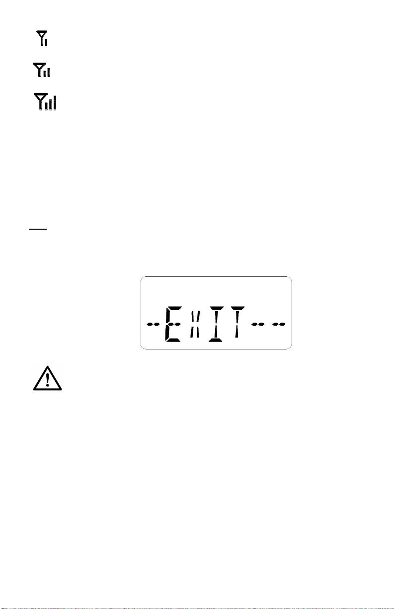
Toexitthemenu,waitfor10secondsandtheLCDscreenwillstopblinking.You
canalsoexitthemenubypressingthe[MENU]buttonseveraltimestonavigate
throughtheoptionsuntilyoureachEXITandpress[MENU]onemoretime.
RFPower:WhileinMenu,pressthe[MENU}buttontonavigatethroughthe
optionsuntilyoureachPOWER.WhenPOWERisblinking,pressthe[UP]/[DOWN]
buttonstochangethepower(between0,1Wand2,0W.)
Pleasenotethatthesepowernumbersareforreferenceonlyandmaynotreflect
theexactpoweroutput.
11
TheLCDdisplaywillindicateMonoorStereostatus(seeFig3&Fig4).
Toexitthemenu,waitfor10secondsandtheLCDscreenwillstopblinking.You
canalsoexitthemenubypressingthe[MENU]buttonseveraltimestonavigate
throughtheoptionsuntilyoureachEXITandpress[MENU]onemoretime.
RFPower:WhileinMenu,pressthe[MENU}buttontonavigatethroughthe
optionsuntilyoureachPOWER.WhenPOWERisblinking,pressthe[UP]/[DOWN]
buttonstochangethepower(between0,1Wand2,0W.)
Pleasenotethatthesepowernumbersareforreferenceonlyandmaynotreflect
theexactpoweroutput.
12
Indicates power between 0.1 W and 0.5 W
Indicates power between 0.6 W and 1.0 W
Indicates power between 1.1 W and 2.0 W
Press [MENU] to confirm the option and to go to the next setting.
The level of transmitted RF power needed depends on your application, coverage
needs and type of antenna. Please always consult an RF engineer and your local
communications authority for any licenses or permits you might need for your
application.
Exit: While in the settings menu, press the [MENU} button to navigate through the
options until you reach the fifth option EXIT and press the [MENU] button one
more time to exit the menu.
Safety Information:
HAZARD! Pacemaker Safety
Before using this transmitter and/ or receivers with a pacemaker or another
medical device, consult your physician or the manufacturer of your pacemaker
or another medical device.
If you have a pacemaker or another medical device, make sure that you are
using this transmitter and/or receivers in accordance with safety guidelines
established by your physician or the pacemaker manufacturer.
WARNING! Damage to your Health
Using earphones or headphones at a loud volume or over a prolonged period
can lead to permanent hearing damage. To protect your hearing and others:
a) Turn down the volume before putting on the earphones or headphones.
b) Adjust the volume at the minimum comfortable level.

13
c) If feedback (a squealing or howling noise) occurs, turn down the
headphone volume, and move the microphone away from the receiver’s
headphones.
Other Safety Considerations
Do not leave the device in places with high temperatures or high humidity.
Do not handle the power cord with wet hands.
Keep this device away from fire and heat sources.
Keep this product, accessories and its packaging out of the reach of children.
Plastic bags, packing material, electrical cords and other accessories may cause
choking, suffocation and/or electrocution!
Do not open the unit. There are no user serviceable parts inside.
Reduce the volume to its lowest setting before use.
To clean, be sure to first switch off and unplug the unit from the power outlet,
then wipe with a dry cloth. When extremely dirty, use a soft cloth dampened in
neutral detergent. Never use benzene, thinner or chemically treated towels,
which may damage the product’s finish.
Trouble shooting
The transmitter will not power.
Verify that the PS-500 power supply is connected to a working power
source and to the transmitter.
Make sure you are pressing and holding the [POWER] button for 5
seconds.
There is no audio on the transmitter’s headphones output.
If you are using the monitor headphones for language interpretation,
make sure the monitor selector is set to EXT (External audio).
Verify that the external audio signal is connected to the external audio
input jack.
Verify that there is a signal coming from your audio source.
If you are using the headphones to monitor the broadcasted audio, make
sure the monitor selector is in the INT (Internal) position.
There is no audio, or the audio is low on the receivers.
Make sure that the main volume is turned up and that your audio source
is properly connected. If using Input 1, the mode selector switch should
be in the correct position. For example: if you are using the output of a
mixer, the switch should be in the LINE position. If using a dynamic
microphone, the switch should be in MIC and if using a 12 V condenser
microphone, the switch should be in MIC PH-PWR.

14
If the audio level is still low, make sure that the gain knob on the rear
panel is turned up.
If using the front microphone jack, make sure that the mute function is off
and that you are using a compatible microphone in working condition.
There is noise or distortion in the audio.
Verify if the audio input level is too high that overloads the input. Adjust
the gain if necessary. If using input 1, make sure you are using the correct
mode selector switch.
Check to see if there is noise or ground loops in the audio source.
Receivers cannot pick up the signal.
Make sure that the transmitter and the receivers are turned on.
Check to make sure the receivers and the transmitter are using the same
frequency.
Ensure the antenna on the transmitter has been properly connected.
There is insufficient range.
Verify that your receivers are working properly.
Make sure the antenna is the correct one for your unit and is adequately
attached to the transmitter with the correct length following the chart
provided in this manual. if you are using a remote antenna, make sure it
was designed for the frequency you intend to use.
If using a remote antenna, keep coaxial cable from transmitter to antenna
as short as possible.
Make sure the transmitting antenna is oriented vertically.
The antenna should be placed as high as possible and free of obstacles.
Avoid placing it inside metal enclosures. Avoid obstacles between the
listening area and the antenna that may affect the signal strength, like
partitions, metal objects, dense materials, studs, pipes, heating or AC
ducts, metal grids or concrete.
Set the transmitter to a higher power level.
Try using a different channel/ frequency since a strong interfering signal
may exist.
Try better receivers. Car radios have longer range than portable radios.

15
FCC Statements:
Caution: Any changes or modifications not expressly approved by the party
responsible for compliance could void the user's authority to operate the
equipment.
This device complies with part 15 of the FCC Rules. Operation is subject to the
following two conditions: (1) This device may not cause harmful interference,
and (2) this device must accept any interference received, including
interference that may cause undesired operation.
IMPORTANT NOTE:
This equipment has been tested and found to comply with the limits for a Class B
digital device, pursuant to part 15 of the FCC Rules. These limits are designed to
provide reasonable protection against harmful interference in a residential
installation. This equipment generates, uses, and can radiate radio frequency
energy and, if not installed and used in accordance with the instructions, may
cause harmful interference to radio communications. However, there is no
guarantee that interference will not occur in a particular installation. If this
equipment does cause harmful interference to radio or television reception, which
can be determined by turning the equipment off and on, the user is encouraged to
try to correct the interference by one or more of the following measures:
—Reorient or relocate the receiving antenna.
—Increase the separation between the equipment and receiver.
—Connect the equipment into an outlet on a circuit different from that to which
the receiver is connected.
—Consult the dealer or an experienced radio/TV technician for help.
FCC Radiation Exposure Statement:
This equipment complies with FCC radiation exposure limits set forth for an
uncontrolled environment. This equipment should be installed and operated with
minimum distance 51cm between the radiator & your body.

16
ISEDC Warning
This device complies with Innovation, Science, and Economic Development Canada
license-exempt RSS standard(s). Operation is subject to the following two
conditions:
(1) this device may not cause interference, and
(2) this device must accept any interference, including interference that may cause
undesired operation of the device.
Le présent appareil est conforme aux CNR d' Innovation, Sciences et
Développement économique Canada applicables aux appareils radio exempts de
licence. L'exploitation est autorisée aux deux conditions suivantes :
(1) l'appareil nedoit pas produire de brouillage, et
(2) l'utilisateur de l'appareil doit accepter tout brouillage radioélectrique subi,
même si le brouillage est susceptible d'en compromettre le fonctionnement.
The device is compliance with RF exposure guidelines, users can obtain Canadian
information on RF exposure and compliance. The minimum distance from body to
use the device is 51cm.
Le présent appareil est conforme Après examen de ce matériel aux conformité ou
aux limites d’intensité de champ RF, les utilisateurs peuvent sur l’exposition aux
radiofréquences et la conformité and compliance d’acquérir les informations
correspondantes. La distance minimale du corps à utiliser le dispositif est de 51cm.

17
Limited Warranty Statement
Enersound warrants the T-588 transmitter to be free from defects in workmanship
and materials under normal use and conditions for one year from the date of
purchase from an official dealer. If the product is determined to be defective,
Enersound will repair or replace it, at its discretion, at no charge. Customer must
pay for shipping. This warranty is void if damage occurred because of misuse or if
the product has been repaired or modified by anyone other than a factory-
authorized service technician. Warranty does not cover any physical damage
unless the damage was the result of a manufacturing defect. Damage due to water,
corrosion, humidity, extreme temperature, chemicals, or any other external factor
is not covered under this warranty. Reimbursement for your costs of removing and
transporting the product for warranty service evaluation or installation of any
replacement product are not covered by this warranty.
Enersound has no control over the conditions under which this product is used.
Therefore, the company disclaims all warranties not set forth above, both express
and implied, with respect to the T-588 transmitter, including but not limited to any
implied warranty of merchantability or fitness for a particular purpose. Enersound
products manufacturer, distributors and/or dealers shall not be liable to any
person or entity for any medical expenses, or any direct, incidental, or
consequential damages caused by any use, defect, failure, or malfunction of the
product, whether a claim for such damages is based upon warranty, contract, tort
or otherwise. The sole remedy for any defect, failure or malfunction of the product
is replacement of the product. No person has any authority to bind Enersound to
any representation or warranty with respect to the Enersound T-588 transmitter.
This warranty gives you specific legal rights, and you may also have other rights
which vary from state to state. Some states do not allow limitations on how long
an implied warranty lasts, and the exclusion or limitation of incidental or
consequential damages, so the above limitation may not apply to you. This
warranty does not cover products sold AS IS or WITH ALL FAULTS. For products
sold outside the U.S., please consult with your local dealer about special terms and
conditions applicable in your country. Proof of purchase in the form of a bill of sale,
invoice number or receipted invoice, which is evidence that the unit is within the
warranty period, must be presented to obtain warranty service. If you experience
any issues with your T-588 transmitter, send an email to support@enersound.com
with your name, address, phone number and a complete description of the
problem. We will respond to you as soon as possible and if it is necessary to return
the product for service, your Customer Service Representative will give you a
Return Authorization Number (RAN) and shipping instructions. For more
information, visit www.enersound.com. You may also call 1-305-731-2416 or
our toll-free number 1-800-644-5090 within the U.S.

18
T-588 Optional Accessories
To purchase accessories, contact your local dealer.
If you are unable to find a dealer in your area, contact us for more information:
Toll free: 1-800-644-5090
International: +1-305-731-2416
www.enersound.com
ANT-588
Replacement Telescoping Antenna
PS-500
Replacement Power Supply
RM-501
Single Rack Mount Kit to mount one T-588 transmitter on a standard 19” rack
RM-502
Dual Rack Mount Kit to mount two T-588 transmitters on a standard 19” rack
COV-500
Top/ Bottom Metal Enclosure Cover for T-588

19
We reserve the right to make technical and design modifications to the transmitter without notice.
© 2022 Enersound. All rights reserved.
Enersound Contact Information:
Toll free: 1-800-644-5090
International: +1-305-731-2416
Specifications: Enersound T-588 FM Transmitter
RF
Operating Frequency
88.1-107.9MHz Odd Frequencies only (US Version)
Frequency Deviation
+/- 75kHz (Maximum Deviation)
Frequency Accuracy
+/- 0.005% stability from 0~+50 degree C
Transmitter Stability
+/- 20ppm
Output Power
2 Watt adjustable
Antenna
Telescoping antenna with 50 ohm impedance or optional remote antenna
Antenna Connector
TNC
Compliance
US: FCC Part 73 , Canada: Industry Canada BETS 6 & RSS-123
AUDIO
Frequency Response
100Hz ~15KHz (+ 3db/-6db)
Signal to Noise Ratio
50db
System Distortion
< 0.3% (THD)
Audio Input 1
3-Pin XLR and ¼” (TRS) combination jack for MIC or LINE level
Balanced or unbalanced. Nominal input level 0/56dbu (0.77V/1.3mV)
(line/mic)
Phantom Power:12VDC PIN 2&3 on XLR or Tip and Ring on ¼” TRS Jack
Audio Input 2
(2)RCA Jacks, unbalanced Stereo Line Level -10dBu nominal, 100k ohms
External Monitor In.
RCA Jack, unbalanced, Line Level -10dBu nominal, 100k ohms.
REC Output
RCA Jack, unbalance output, Line Level -10dBu nominal, 10 ohms.
MIC Input
Front panel: 3.5mm 1/8’’ TRS jack, supplies +DC on tip for electret mics.
Audio Processing
Built-in signal compression 2:1.
Headphone Out.
Front panel: 3.5mm stereo TRS jack adjustable output level,
Max Power 61mW @8ohm, Impedance: 4~16ohm.
POWER
Power Supply Type
In Line, UL listed
Power Supply In.
100~240VAC, 50-60Hz
Power Supply Out.
15VDC, 1A
Power Supply
Connector
Output Connector: .02 in.(5.0 mm) OD, .01 in.(2.5mm) ID, barrel type
ENVIROM.
Temp. Operation
-5℃(23F) to + 40℃(104F)
Temp. Storage
-20℃(-4F) to + 60℃(140F)
Humidity
0~95% Relative Humidity
PHYSICAL
Dimensions
5” x 5.5” x 1.75” (127 x 140 x 45 mm) (DxWxH)
Color
Black
Unit Weight
1.2 lbs. (0.54 Kg)
Power Supply
Weight
0.5 lbs. (0.22 Kg) with AC cord
Shipping Weight
2.2 lbs. (1.1 Kg)
Rack Mounting
1 1/2 rack space height, 1/2 rack space wide, One or Two transmitters can
be mounted in 1.5 rack space, Option rack mount (RM-501 or RM-502)

Other manuals for T-588
2
Table of contents
Other Enersound Transmitter manuals


Popular Transmitter manuals by other brands


RHEONIK
RHEONIK RHE21 Installation & start?up guide

ADEMCO
ADEMCO 5804BDV installation instructions

M-system
M-system 10JV instruction manual

Canon
Canon Wireless File Transmitter WFT-E7A instruction manual

Endress+Hauser
Endress+Hauser Levelflex FMP 232 Quick setup

Well Straler
Well Straler RC-16A-TX user guide


