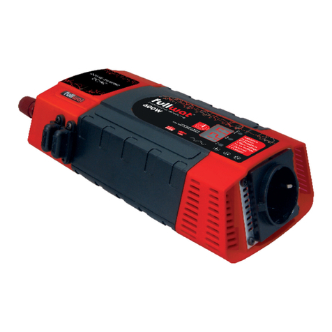
Fullwat PDA500SS User manual

5VDC=2.1A
PDA500SS / PDA700SS / PDA1200SS / PDA2000SS
Convertidor DC/AC
Power inverter DC/AC
Manual de instrucciones ........... página 3
User manual .............. page 12


- 3 -
1.INFORMACIÓN DE SEGURIDAD IMPORTANTE
Advertencias
Antes de instalar y utilizar el inversor debe leer atentamente la siguiente información de seguridad.
1.1 Precauciones generales de seguridad
1.1.1 No exponga el inversor a la lluvia, nieve, rocío o polvo. Para reducir los riesgos, no cubrir u obstruir las aberturas de ventilación.
No instale el convertidor en un compartimente sin espacio libre, podría provocar un sobrecalentamiento.
1.1.2 Para evitar el riesgo de incendios y choques eléctricos compruebe que el cableado existente esté en buenas condiciones
y que el tamaño de los cables no sea inferior al necesario. No hacer funcionar el convertidor con cables dañados o de
tamaño inferior al necesario.
1.1.3 Este equipo contiene componentes que pueden producir arcos o chispas. Para reducir el riesgo de incendio o explosión,
no instale el convertidor en un compartimento que contenga baterías o materiales inflamables, o en una ubicación que
necesite un equipo protegido contra ignición, esto incluye cualquier espacio que contenga maquinaria a gasolina, tanques
de combustible o juntas, accesorios u otra conexión entre los componentes sistema de combustible.
1.2 Precauciones cuando se trabaja con baterías
1.2.1 Si el ácido de la batería entra en contacto con la piel o la ropa, lave inmediatamente con agua y jabón. Si el ácido entra
en contacto con los ojos, lávese inmediatamente con agua fría durante al menos 20 minutos y acuda a un médico de
inmediato.
1.2.2. Nunca fume o provoque chispas o llamas en los alrededores de baterías o motores.
1.2.3 No deje caer herramientas metálicas sobre la batería. Las chispas o cortocircuitos resultantes en la batería u otra parte
eléctrica pueden causar una explosión.
1.2.4 Quítese los objetos metálicos personales como anillos, pulseras, collares y relojes cuando trabaje con una batería de plomo-
ácido. Una batería de plomo-ácido produce una corriente de cortocircuito suficientemente alta como para soldar un anillo
al metal, causando quemaduras graves.
2.CARACTERÍSTICAS
• Salida de onda sinusoidal pura ﹙THD<2%﹚.
• Admite interfaz de comunicación RS485, la distancia de control remoto puede alcanzar más de 1000m.
• Polaridad inversa controlada por MOS, sin fusible.
• Los parámetros se pueden configurar de acuerdo con los diferentes usos.
• Entradas y salidas de diseño completamente aislado.
• La pantalla LCD muestra el estado de funcionamiento y la condición de error.
• Capaz de impulsar cargas inductivas y capacitivas en el momento de arranque.
• Ventilador de enfriamiento controlado por carga y temperatura.
• Microprocesador avanzado incorporado que hace que la interfaz sea agradable para el usuario.
• Material ignífugo y responsable con el medio ambiente.
• Protección: alarma de baja tensión de entrada y apagado, sobrecarga, cortocircuito, sobretensión de entrada, sobrecalentamiento.
• Puerto de salida USB 5V 2.1A.
3.Diseño mecánico
Inversor de onda
sinusoidal pura de
1200W
nversor de onda
sinusoidal pura de
500W/700W
340,3
362,3
245,0
110,0
113,3
15,2
8,8
270,6
261,8
7,0
5,2
284,1
32,0
150,0
78,6

- 4 -
Inversor de onda
sinusoidal pura de
2000W
245,0
400,3
422,3
110,0
113,3
15,2
8,8
Accesorios
1
2
3
4
5
2 5
1
3 4
Puerto USB con PC
Puerto de conversión RS485 - USB
Indicador de potencia y datos de flujo del convertidor
﹙POWER: indicación de potencia RXD: indicación de
recepción de datos TXD: indicación de transmisión de datos﹚
Orificio para montaje
Puerto de comunicación
Inversor de onda
sinusoidal pura de
3000W
Inversor de onda
sinusoidal pura de
4000W
245,0
113,3 460,3
482,3
110,0
15,2
8,8
Función opcional:
Conexión RS485, puede monitorizar los
datos en tiempo real en el ordenador. G A B
245,0
113,3 520,3
542,3
110,0
15,2
8,8

- 5 -
4.Iconos de pantalla LCD
4.1 Botones
1. SET/OK: Botón de configuración, botón intro.
2. UP: Botón de configuración ﹙Arriba﹚.
3. DOWN: Botón de configuración ﹙Abajo﹚.
4. MENU/ESC: Botón de menú, botón salir.
5. ON/OFF: Interruptor de encendido/apagado.
4.2 Pantalla normal
Notas:
• Presionar ‘’ESC’’ para seleccionar la indicación del icono 3 ﹙Tensión de salida, corriente, potencia, frecuencia﹚. Presionar “Up”
para seleccionar o establecer el cambio automático de los datos del icono 3.
• Presionar y mantener los botones “UP” y “DOWM” al mismo tiempo durante 3s hasta que la luz de fondo de la pantalla
parpadee 3 veces y los parámetros se restablezcan a los valores predeterminados de fábrica.
• Cuando no hay errores, la luz de fondo de la pantalla LCD se apaga automáticamente cuando no se utiliza el botón durante
30s. Cuando hay un error o se toca el botón, la pantalla LCD se enciende automáticamente.
4.3 Pantalla de error
Cuando ocurren errores: el icono
2 indica el código correspondiente
y parpadea con un código de
advertencia, la luz de fondo de la
pantalla LCD siempre se mantiene
encendida.
4.4 Interfaz de configuración
Mantenga presionado “SET/OK” durante 5s para ingresar en la interfaz de configuración
que se muestra en la figura anterior. Mientras el icono 1 se mantiene fijo, el icono 3
parpadea para configurar los parámetros y el icono 2 parpadea para configurar el
código de interfaz.
Presione “UP” y “DOWN” para ajustar los parámetros, después presione “SET/OK” para
confirmar el ajuste.
Si desea restablecer los parámetros, presione brevemente “SET” hasta que el icono 1
parpadee.
Presione “ESC” para cancelar este paso y cambiar directamente a la siguiente interfaz
de configuración. Mantenga presionado “ESC” durante 5s para salir de la interfaz de
configuración a la interfaz principal. Si durante más de 10s no hay ninguna operación,
la interfaz volverá automáticamente a la interfaz principal.
POWER
FAULT
SET
OK
MENU
ESC
ON
OFF
DOWN
UP
23.1
v
BA TT
1
23 4
v
OU TP UT
~
100%
231
v
BA TT
1
23 4
v
OU TP UT
~
100%
6
5
1
v
BA TT
02
000
v
OU TP UT
~
100%
!
ERROR
5
0
1
v
BA TT
01
~
100%
NO Icon Function description
1N
231
v
BA TT
OIndica la tensión de salida de la batería
2
1
Indica los programas de configuración o códigos de alarma o
error. ﹙Cuando el producto funciona normalmente, el icono gira
en sentido horario; cuando el producto falla, muestra los códigos
de error.﹚
3
23 4
v
OU TP UT
Indica voltaje de salida, corriente, potencia, frecuencia
4Indica el nivel de la batería
5~DC/AC inversor funcionando
6
100%
Indica el porcentaje de nivel de carga
Error Código
Batería baja 01
Sobretensión de la batería 02
Temperatura alta en el circuito frontal 03
Temperatura alta en el circuito posterior 04
Temperatura alta en el circuito frontal y posterior 05
Sobrecarga en la salida 08
Cortocircuito en la salida 09

- 6 -
Notas
Valor de aviso de tensión baja = valor de cierre de tensión baja + 0.5V,
Valor de aviso de sobretensión = valor de cierre de sobretensión - 0.5V.
5.REALIZAR LAS CONEXIONES DE CABLEADO DC
Siga este procedimiento para conectar los cables de la batería a los terminales de entrada DC del inversor.
El cable debe ser lo más corto posible ﹙lo ideal es usar los cables de repuesto del fabricante﹚ para manejar la corriente requerida
de acuerdo con los códigos o regulaciones eléctricas. Unos cables que no tengan la sección adecuada ﹙demasiado pequeña o
demasiado grande﹚ reducirán el rendimiento del inversor, por ejemplo reducción de la capacidad de sobretensión y advertencias
frecuentes de baja tensión de entrada y detenciones. El aviso de protección por tensión baja se presenta debido a la caída de
tensión DC a través de los cables entre el inversor y las baterías.
Cuanto más largos o estrechos sean los cables, mayor será la caída de voltaje.
Aumentar la sección del cable DC ayudará a mejorar esta situación.
Advertencias
La instalación de un fusible debe realizarse en el cable positivo. Si no se coloca el fusible en los cables “+” que se extienden entre el
inversor y la batería, puede dañar el inversor y anulará la garantía.
6.SOLUCIÓN DE PROBLEMAS
Advertencia
No abra ni desmonte el inversor. Intentar reparar la unidad usted mismo supone un riesgo de descarga eléctrica o incendio.
7.MANTENIMIENTO
Debe limpiar el exterior de la unidad periódicamente con un paño húmedo para evitar la acumulación de polvo y suciedad. Al
mismo tiempo, apriete los tornillos en los terminales de entrada DC.
Interfaz de comunicación Código Rango
Valor de protección por tensión baja 01
12V Por defecto: 10.5 Ajuste: 10.0-11.0
24V Por defecto: 21.0 Ajuste: 20.0-22.0
48V Por defecto: 42.0 Ajuste: 40.0-44.0
Valor de recuperación de tensión baja 02
12V Por defecto: 12.0 Ajuste: 11.5-12.5
24V Por defecto: 24.0 Ajuste:23.0-25.0
48V Por defecto: 48.0 Ajuste: 46.0-50.0
Valor de protección por sobretensión 03
12V Por defecto: 15.3 Ajuste: 15.2-16.0
24V Por defecto: 30.6 Ajuste: 30.4-32.0
48V Por defecto: 61.2 Ajuste: 60.8-64.0
Valor de recuperación de sobretensión 04
12V Por defecto: 14.7 Ajuste: 14.5-15.0
24V Por defecto: 29.4 Ajuste: 29.0-30.0
48V Por defecto: 58.8 Ajuste: 58.0-60.0
Modo de cortocircuito de sobrecarga 05 Por defecto: 0 Ajuste: 0:bloqueado 1:reiniciar
Valor de ajuste de sobrecarga 06 Por defecto: 0 Ajuste: 0:bloqueado 1:reiniciar
Reinicio del valor de cortocircuito de sobrecarga 07 Por defecto: 10 Ajuste: 5-60S
Modo de alarma 08 Por defecto: 0 Ajuste: 0:Abierto 1:Cerrado
Comunicación 09 Por defecto: 1 Ajuste: 1-255
Fault Code Solution
Batería baja 01 Detenga el uso del inversor y cargue la batería; Reempla-
ce el cable de conexión por uno más grueso
Sobretensión de la batería 02 Verifique que la tensión de la batería sea la correcta;
Verifique el voltaje de carga
Temperatura alta en el circuito frontal 03 Mejore la ventilación; Asegúrese de que la temperatura
ambiente esté entre 0~40ºC; Reduzca o apague las
cargas un tiempo para bajar la temperatura
Temperatura alta en el circuito posterior 04
Temperatura alta en el circuito frontal y posterior 05
Sobrecarga en la salida 08
Haga que la potencia de la carga sea menor que la
potencia nominal (si las cargas inductivas o capacitivas
son varias veces superiores a la potencia nominal en el
arranque, reemplace por un inversor de mayor potencia)
Sobrecarga en la salida 09 Desconecte las cargas y compruebe si es un cortocircuito

- 7 -
Apéndice:
Instrucciones de la plataforma de monitoreo de la serie PX
1. Instalación de software:
Descargue los archivos de la web oficial de Fullwat www.fullwat.com:
PX Monitoring System V1.1.exe,
Como sigue:
2. Instalación del driver RS485 del convertidor aislado
(Si ya está instalado puede ignorar este paso):
Si es un convertidor de nuestra empresa, por favor
visite nuestra web para descargar, o busque la
siguiente figura del convertidor aislado RS485: archivo
CDM21224_Setup.exe, doble clic para instalar.
3. Plataforma de monitoreo de inicio de sesión:
Tras confirmar que el producto está conectado al
convertidor aislado RS485 y al PC, hacer clic en Start -
All Programs – PX Monitoring System V1.1, la interfaz es
como sigue:
Después de iniciar sesión, la interfaz de monitoreo es la
siguiente:
Doble clic en ,
para instalar
:
Complete el nombre de usuario y el
nombre de la empresa, clic en “Next”
para ingresar
Clic en “Next” para ingresar en la
pantalla siguiente.
Clic en “Change…” para confirmar la ruta de
instalación recomendada por defecto. En la
siguiente interfaz, clic en “Next”. Clic en “Finish”
para completar la instalación.
Acepte los términos y pulse “Next”
para ingresar en la pantalla siguiente.
Seleccione el número de puerto serie “ComNum” que
corresponda al convertidor RS485, haga clic en “OpenCom”
para abrir el puerto serie; para salir del sistema, haga clic en
“Salir” o “X” en la esquina superior derecha. La interfaz de datos
de monitoreo de operaciones se muestra a continuación:

- 8 -
Protocolo de comunicación
1.1 Descripción general
Este producto utiliza el protocolo de comunicación Modbus-RTU, interfaz RS485. El protocolo Modbus define el código de
verificación, la secuencia de datos, etc., todo esto es necesario para un intercambio de datos específico. El protocolo Modbus
utiliza una estructura de conexión maestro-esclavo ﹙half duplex﹚ en una línea de comunicación, lo que significa que la señal se
transmite en la dirección opuesta en una línea de comunicación separada. Primero, la señal del maestro se direcciona a un
único dispositivo terminal ﹙esclavo﹚, luego, la señal de respuesta enviada por el dispositivo terminal es transmitida al maestro en la
dirección opuesta.
El protocolo Modbus solo permite la comunicación entre el maestro ﹙PC, etc.﹚ y el esclavo, y no permite el intercambio de datos
entre esclavos independientes, de modo que cada dispositivo terminal no ocupe la línea de comunicación cuando se inicializan,
sino que responde a la señal de petición de la máquina local.
1.1.1 Método de transferencia
La transmisión de información es asíncrona, y la información de comunicación transmitida entre el maestro y el esclavo está
en bytes, incluyendo 1 bit de inicio, 8 bits de datos ﹙el bit menos significativo se envía primero﹚, sin paridad, 1 bit de parada.
1.1.2 Formato de la estructura de información
Código de
dirección Código de
función Área de datos Código de
vericación CRC
1 byte 1 byte n bytes 2 bytes
Código de dirección: El código de dirección está compuesto por un byte ﹙código binario de 8 bits﹚ al comienzo de la
estructura, y es un decimal de 1 a 255. Estos bits indican la dirección del dispositivo terminal especificado por el usuario que
será el que reciba los datos desde el máster. La dirección de cada esclavo debe ser única, y solo el terminal direccionado
responderá a la solicitud que contiene la dirección. Cuando el terminal devuelve una respuesta, los datos de la dirección del
esclavo en la respuesta le indican al maestro qué terminal se está comunicando con él.
Código de función: El código de función indica qué terminal está realizando qué función. La siguiente tabla enumera los
códigos usados en esta serie de instrumentos, así como su significado y función.
Área de datos: El área de datos contiene los datos requeridos por el terminal para realizar una función específica o los
datos recopilados por el terminal en respuesta a la consulta. El contenido de estos datos puede ser numérico, dirección de
referencia o un valor establecido. Por ejemplo, el código de función le pide al terminal que lea un registro, y el área de datos
necesita indicar en qué registro comenzar y cuántos datos leer. La dirección y los datos integrados varían según el tipo y los
diferentes contenidos entre los esclavos.
Código de verificación CRC: El campo de verificación de error ﹙CRC﹚ ocupa dos bytes y contiene un valor binario de 16
bits. El valor de CRC es calculado por el dispositivo de transmisión y después se agrega a la estructura de datos. El dispositivo
receptor recalcula el valor de CRC cuando recibe los datos, y después lo compara con el valor del campo CRC recibido. Si
estos dos valores no son iguales se produce un error
1.2 Leer registros de enumeración de datos
Esta característica permite al usuario obtener datos y parámetros del
sistema recopilados y registrados por el dispositivo. El máster puede leer
uno o más valores de registro y puede leer hasta 12 valores de registro
a la vez ﹙no puede exceder el rango de direcciones definido﹚.
El siguiente ejemplo son los datos
básicos recopilados de la lectura
de la máquina ﹙el marco de datos
ocupa 2 bytes por dirección﹚ tensión
de salida, corriente de salida,
frecuencia de salida, donde la
dirección de la tensión de salida es
0001H, la dirección de la corriente
de salida es 0002H, y la dirección
de la frecuencia de salida es 0003H.
Indicaciones
Tensión de salida ﹙V﹚: Convertir 0x00+0xE3 a decimal, igual a 227
Corriente de salida ﹙A﹚: Convertir 0x00+0xE6 a decimal, 230/100=2.3
Frecuencia de salida ﹙Hz﹚: Convertir 0x00+0x32 a decimal, igual a 50
Dirección de esclavo 1-255
Código de función 0x03
Dirección alta de inicio de registro 0x00
Dirección baja de inicio de registro 0-23
Longitud de registro alto 0x00
Longitud de registro bajo 1-12
Comprobación CRC bajo
Comprobación CRC alto
Dirección de esclavo 0x01
Código de función 0x03
Dirección alta de inicio de registro 0x00
Dirección baja de inicio de registro 0x01
Longitud de registro alto 0x00
Longitud de registro bajo 0x03
Comprobación CRC bajo 0x54
Comprobación CRC alto 0x0B
Dirección de esclavo 0x01
Código de función 0x03
Longitud de registro 0x06
Registro alto 0x00
Registro bajo 0xE3
Registro alto 0x00
Registro bajo 0xE6
Registro alto 0x00
Registro bajo 0x32
Comprobación CRC bajo 0x84
Comprobación CRC alto 0x81
- 9 -
1.3 Lista de parámetros de dirección
1.3.1 Tabla de correspondencia de registro de ajuste de modo
1.3.2 Tabla de correspondencia de registro de información de errores
1.4 Cableado de la interfaz de comunicación
Conecte la interfaz A de comunicación del producto a la interfaz A de comunicación del convertidor RS485, B a la interfaz de
comunicación del convertidor RS485 B; preste atención al cableado A y B cuando realice la conexión, de lo contrario no podrá
realizar la comunicación adecuadamente ﹙G es el bloque de terminales de la protección del cable de comunicación, se puede
conectar o no﹚.
Bit 15 14 13 ...... 5 4 3 2 1 0
Nombre Reservado
MODO1 MODO0
Reservedo
Bit Detalle
0-1 Reservedo
2MODO 0: Sobrecarga en modo de cortocircuito
0: Reinicio automático 1: Sin salida bloqueada, necesario reiniciar
3MODO 1: Modo de sonido de alarma
0: Aviso anticipado/sonido de error 1: Silencio
4-15 Reservedo
Dirección de registro Contenido de datos Descripción de los datos Tipo
0000 Tensión de la batería (Registro alto + registro bajo)/10 Palabra
0001 Tensión de salida Registro alto + Registro bajo Palabra
0002 Corriente de salida (Registro alto + registro bajo)/10 Palabra
0003 Frecuencia de salida Registro alto + Registro bajo Palabra
0004 Valor de retardo de reinicio Registro alto + Registro bajo Palabra
0005 Valor de protección de tensión baja Registro alto + Registro bajo Palabra
0006 Valor de recuperación de tensión baja Registro alto + Registro bajo Palabra
0007 Valor de protección contra sobretensión Registro alto + Registro bajo Palabra
0008 Valor de recuperación de tensión alta Registro alto + Registro bajo Palabra
0009 valor de ratio de sobrecarga Registro alto + Registro bajo Palabra
0010 Valor de ajuste de modo Ver la tabla de ajustes de modo para
más detalles Palabra
0011 Información de error Ver la tabla de información de errores
para más detalles Palabra
Bit Detalle
0-1 ERROR0: Error de sobretensión de la batería
00: Normal 01: Tensión baja 10: Sobretensión
2-3
ERROR1: Error de temperatura alta 00: Normal
01: Temperatura alta en el circuito frontal
10: Temperatura alta en el circuito posterior
11: Temperatura alta en la parte frontal y posterior
4-5 Reservedo
6-7 ERROR3: Error de salida
00: Normal 01: Sobrecarga 10: Cortocircuito
8-15 Reservedo
Bit 15 14 13 ...... 9 8 7 6 5 4 3 2 1 0
Nombre Reservedo ERROR2
Reservedo
ERROR1 ERROR0

- 10 -
Garantía
Los inversores FULLWAT son un dispositivo con de carácter industrial dotados de una compleja tecnología electrónica que requiere de
una instalación profesional o asistida por personal capacitado. Estos dispositivos son productos industriales destinados a formar parte
de una instalación eléctrica que proporcione energía alternativa y autónoma a la red principal.
Este aparato debe ser adquirido en un distribuidor profesional de electrónica o electricidad. Como bien de naturaleza industrial, su
garantía es de 1 año contado a partir de la fecha de compra, reflejado en la factura o tique de compra, los cuales son de obligada
presentación para que esta garantía sea efectiva. Durante el periodo de garantía, los materiales de reparación y la mano de obra de
reparación están cubiertos durante un año. Para ello se debe enviar el dispositivo defectuoso al establecimiento distribuidor junto con
la factura o tique de compra.
Esta garantía se considerará anulada si el equipo ha sufrido algún tipo de daño físico, manipulación o alteración interna o externa
acometidas por personal no autorizado o independiente a la organización de la marca FULLWAT. Tampoco se cubren daños debidos
a un mal uso del usuario o instalador, como conectar el equipo a fuentes de potencia inadecuadas para el mismo, o someterlo a
condiciones climáticas adversas e inapropiadas.
Es de extremada importancia seguir las recomendaciones de este manual para la instalación de estos inversores para evitar cualquier
manipulación o conexión inapropiada, especialmente en el caso de dispositivos que apliquen cargas inductivas al inversor. En este
caso, utilice siempre un inversor de onda sinusoidal pura.
Esta garantía es únicamente válida para este aparato: no se reparará o reemplazarán los aparatos que hayan podido ser dañados
como consecuencia del mal uso del convertidor.
Todos los convertidores de la serie PDA están cubiertos por un periodo de garantía de 1 año a partir de la fecha de compra por parte
del usuario final.
¿Qué cubre la garantía?
Nuestra garantía cubre todos los defectos del dispositivo debidos a problemas de fabricación.
¿Qué no cubre la garantía?
Todos los daños causados por el incorrecto uso del dispositivo. Es indispensable leer previamente el manual de instrucciones antes de
comenzar a usar el dispositivo. La garantía será cancelada si:
* Desaparece la etiqueta con el número de serie, está manipulada o arrugada.
* Hay signos evidentes de manipulación en los tornillos de la carcasa externa del aparato.
* Se han sustituido algunos de los componentes originales del inversor, como cables de conexión, tornillos, interruptores o similares.
* El fusible de entrada ha sido reemplazado por uno de mayor amperaje.
* El tique de garantía con la fecha y el sello del vendedor no es propiedad de UKAI, S.A.
* El inversor ha sido forzado a trabajar repetidamente con potencias superiores a la potencia nominal del mismo.
Importante
* El número de serie y la fecha de venta al distribuidor de cada convertidor se registran en nuestro sistema informático. Cualquier
retraso de más de 6 meses entre los datos registrados en nuestro sistema y los datos de la factura emitida por nuestros
distribuidores, se interpretarán como datos incorrectos y se cancelará la garantía. Solicite una factura o tique en el momento de la
compra. Para que la garantía sea efectiva en caso de necesidad de reparación, envíe el aparato con su factura o tique, donde
se muestre el número de serie original, y una nota con la descripción de los síntomas del daño.


- 12 -
1.IMPORTANT SAFETY INFORMATION
Warning
Before installing and using the inverter, you need to read the following safety information carefully.
1.1 General safety precautions
1.1.1 Do not expose the inverter to rain, snow, spray, bilge or dust.
To reduce risk of hazard, do not cover or obstruct the ventilation openings.
Do not install the inverter in a zero-clearance compartment, may result in overheating.
1.1.2 Do avoid a risk of fire and electronic shock. Make sure that existing wiring is in good electrical condition; and that wire size is not
undersized. Do not operate the inverter with damaged or substandard wiring.
1.1.3 This equipment contains components which can produce arcs or sparks. To prevent fire or explosion, do not install in
compartments containing batteries or flammable materials or in locations where require ignition protected equipment,
this includes any space containing gasoline-powered machinery, fuel tanks, or joints, fittings, or other connection between
components of the fuel system.
1.2.Precautions when working with batteries
1.2.1 If battery acid contacts skin or clothing, washes immediately with soap and water. If acid enters eye, immediately flood eye
with running cold water for at least 20minutes and get medical attention immediately.
1.2.2 Never smoke or allow a spark or flame in vicinity of battery or engine.
1.2-3 Do not drop a metal tool on the battery. The resulting sparks or short-circuits on the battery of other electrical part may cause
an explosion.
1.2.4 Remove personal metal items such as rings, bracelets, necklaces, and watches when working with a lead-acid battery. A lead-
acid battery produces a short-circuit current high enough to weld a ring or the like to metal, causing a severe burn.
2.FEATURES
• Pure sine wave output ﹙THD<2%﹚.
• Adopts RS485 communication interface, the remote control distance can reach more than 1000m.
• Reverse polarity controlled by MOS, without fuse burt.
• Parameters can be set according to different usage.
• Input & output completely isolated design.
• LCD displays operation status, and error condition.
• Capable of driving inductive & capacitive loads at the start moment.
• Loading and temperature controlled the cooling fan.
• Built in advanced microprocessor to make friendly interface with user.
• Flame retardant and environment friendly material.
• Protection: input low voltage alarm & shutdown, overload, short circuit, input over voltage, over temperature.
• USB output port 5V2.1A.
3.Mechanical drawing
Pure sine wave inverter
1200W
Pure sine wave inverter
500W/700W
340,3
362,3
245,0
110,0
113,3
15,2
8,8
270,6
261,8
7,0
5,2
284,1
32,0
150,0
78,6

- 13 -
Pure sine wave inverter
2000W
245,0
400,3
422,3
110,0
113,3
15,2
8,8
Accesories
1
2
3
4
5
2 5
1
3 4
USB port with PC
RS485 Converter USB port
Power and Data flow indicator of converter
﹙POWER: power indication RXD: reception indication
TXD: data transmission indication﹚
Mounting hole
Communication port
Pure sine wave inverter
3000W
Pure sine wave inverter
4000W
245,0
113,3 460,3
482,3
110,0
15,2
8,8
Optional function:
RS485 connection, can monitor
the real-time data on computer G A B
245,0
113,3 520,3
542,3
110,0
15,2
8,8

- 14 -
4.LCD Display Icons
4.1 The button
1. SET/OK: Setting button, enter button.
2. UP: Setting button ﹙UP﹚.
3. DOWN: Setting button ﹙DOWN﹚.
4. MENU/ESC: Menu button, exit button.
5. ON/OFF: Power on/off switch.
4.2 The normal display
Noted:
• Press ‘’ESC’’ to select the indication of the Icon 3 ﹙Output voltage, current, power, frequency﹚ Press “Up” to select or set auto
switch the data of Icon 3.
• Press and hold “UP” and “DOWM” button 3S at the same time until the display backlight flashes 3 times and the data parameters
are restored to the factory default values;
• When no fault , the LCD screen backlight automatically turns off when the button is not operated for 30s. When there is a fault or
touch the button, the LCD screen automatically lights up.
4.3 The fault display
When faults occur: the Icon 2
indicate the corresponding code,
and the flashing with warning code,
the LCD screen backlight is always lit.
4.4 The setting interface
Long press “SET/OK” for 5s, enter the setting interface as shown above, while Icon 1, Icon
3 flashing settings parameters, Icon 2 flashing settings interface code;
Press “UP” and “DOWN” to adjust parameters, then press “SET/OK” to confirm the
adjustment.
If re-set the parameter, short press “SET” to make Icon 1 flashing;
Pressing the “ESC” to cancel this step and switch to next setting interface directly.
Long press “ESC” for 5s, exit setting interface to the main interface; more than 10s
without any operation,the interface will automatically return to the main interface.
Noted
Undervoltage warning value = undervoltage closing value + 0.5V,
overvoltage warning value = overvoltage closing value - 0.5V.
POWER
FAULT
SET
OK
MENU
ESC
ON
OFF
DOWN
UP
23.1
v
BA TT
1
23 4
v
OU TP UT
~
100%
231
v
BA TT
1
23 4
v
OU TP UT
~
100%
6
5
1
v
BA TT
02
000
v
OU TP UT
~
100%
!
ERROR
5
0
1
v
BA TT
01
~
100%
NO Icon Function description
1N
231
v
BA TT
OIndicate battery output voltage
2
1
Indicate the setting programs or warning and fault codes
﹙When the product runs normally: the icon rotates clockwise;
when the product fails, display the fault codes.﹚
3
23 4
v
OU TP UT
Indicate output voltage, current, power, frequency
4Indicate battery level
5~DC/AC inverter working
6
100%
Indicate the percentage of load level
Fault Code
Battery low voltage 01
Battery over voltage 02
Front-end circuit over temperature 03
Back-end circuit over temperature 04
Front and backend over temperature 05
Output overload 08
Output short circuit 09

- 15 -
5.MAKING DC WIRING CONNECTIONS
Follow this procedure to connect the battery cables to the DC input terminals of the inverter. Your cable should be as short as possible
﹙ideally to use factory spare cables﹚ enough to handle the required current in accordance with the electrical codes or regulations
application. Cables are not an adequate gauge﹙ too narrow﹚ or too long will decrease the inverter performances such as poor surge
capability and low input voltage warnings frequently and shutdowns. UVP warning presents due to DC voltage drop across the cables
from the inverter to the batteries.
The longer or narrower the cables, the greater the voltage drop.
Increasing your DC cable size will help improve the situation.
Warning
The installation of a fuse must be on positive cable. Failure to place a fuse on “+” cables running between the inverter and battery may
cause damage to the inverter and will void warranty.
6.TROUBLE SHOOTING
Warning
Do not open or disassemble the inverter. Attempting to service the unit yourself may result in a risk of electrical shock or fire.
7.MAINTENANCE
You should clean the exterior of the unit periodically with a damp cloth to prevent accumulation of dust and dirt. At the same time,
tighten the screws on the DC input terminals.
Setting interface Code Range
Undervoltage protection value 01
12V Default: 10.5 Setting: 10.0-11.0
24V Default: 21.0 Setting: 20.0-22.0
48V Default: 42.0 Setting: 40.0-44.0
Undervoltage recovery value 02
12V Default: 12.0 Setting: 11.5-12.5
24V Default: 24.0 Setting:23.0-25.0
48V Default: 48.0 Setting: 46.0-50.0
Overvoltage protection value 03
12V Default: 15.3 Setting: 15.2-16.0
24V Default: 30.6 Setting: 30.4-32.0
48V Default: 61.2 Setting: 60.8-64.0
Overvoltage recovery value 04
12V Default: 14.7 Setting: 14.5-15.0
24V Default: 29.4 Setting: 29.0-30.0
48V Default: 58.8 Setting: 58.0-60.0
Overload Short Circuit Mode 05 Default: 0 Setting 0: lock 1:restart
Overload setting value 06 Default: 0 Setting 0: lock 1:restart
Overload Short Circuit Restart Delay Value 07 Default: 10 Setting: 5-60S
Alarming mode 08 Default: 0 Setting 0:Open 1:Close
Communication 09 Default: 1 Setting: 1-255
Fault Code Solution
Battery low voltage 01 Stop using the inverter and to charge the bat-
tery;Replace a thicker connection cable.
Battery over voltage 02 Check the battery voltage is right; Check the
charging voltage
Front-end circuit over temperature 03 Improve ventilation;Make sure the environment
temperature is between 0~40ºC; Reduce
or turn off the loads for a while to lower the
temperature
Back-end circuit over temperature 04
Front and backend over temperature 05
Output overload 08
Make the loads power is smaller than rated
power (Inductive or capacitive loads are seve-
ral times than the rated power when starting,
please replace higher power inverter)
Output short circuit 09 Disconnect the loads and check if it is short
circuit

- 16 -
Appendix:
PX series monitoring platform instructions
1. Software installation:
Download files from Carspa official website on location www.fullwat.com:
PX Monitoring System V1.1.exe,
As below:
2. RS485 Isolated converter driver installation
(This step can be ignored if it has already installed):
If it is a converter with our company, please go to our
website to download, Or, find the following figure from
RS485 isolation converte: CDM21224_Setup.exe file,
double click to install.
3. Login monitoring platform:
After confirming that product is connected to the RS485
isolation converter and PC, click: Start - All Programs - PX
Monitoring System V1.1, the interface is as follows:
After startup, login monitoring interface is as follows:
Dou
ble click to
install, enter the interface as follows:
Fill in the user name and company
name, click “Next” to enter following,
Click “Next” to enter following picture.
Click “Change...” to confirm the installation
path which is recommended to default.
Then the following interface will appear.
Click “Next” until installation is completed
Double click “°” to install, enter the
interface as fol
lows:
Select the serial port number “ComNum” corresponding
to the RS485 converter, click to open the serial port button
“OpenCom”, exit the system, click “Exit” or the upper right
corner “X”, the operation monitoring data interface is as
shown below:

- 17 -
Communication protocol
1.1 Overview
This product uses Modbus-RTU communication protocol, RS485 interface, Modbus protocol defines check code, data sequence,
etc., these are all necessary for specific data exchange. Modbus protocol uses master-slave acknowledgment connection
﹙half duplex﹚ on one communication line, this means that the signal is transmitted in the opposite direction on a separate
communication line. First, the signal of the host computer is addressed to a unique terminal device ﹙slave﹚, then, the response signal
sent by the terminal device is transmitted to the host in the opposite direction.
Modbus protocol only allows communication between host ﹙PC, etc.﹚ and terminal device, and does not allow data exchange
between independent terminal devices, so that each terminal device does not occupy the communication line when they initialize,
but only responds to the inquiry signal reaching the local machine.
1.1.1 Transfer method
Information transmission is asynchronous, and the communication information transmitted between the master and the slave is
in bytes, including 1 start bit, 8 data bits ﹙the smallest valid bit is sent first﹚, no parity, 1 stop bit.
1.1.2 Information frame format
Adress code Function code Data area CRC check code
1 byte 1 byte n bytes 2 bytes
Address code: The address code is composed of one byte ﹙8-bit binary code﹚ at the beginning of the frame, and the
decimal is 1 to 255. These bits indicate the address of the user-specified terminal device that will receive the host data from
it. The address of each terminal device must be unique, and only the addressed terminal will respond to the query containing
the address. When the terminal sends back a response, the slave address data in the response tells the host which terminal is
communicating with it.
Function code: The function code tells the terminal which terminal is performing what function. The following table lists the
function codes used in this series of instruments, as well as their meaning and function.
Data area: The data area contains the data required by the terminal to perform a specific function or the data collected by
the terminal in response to the query. The content of these data may be numeric, reference address or set value. For example,
the function code tells the terminal to read a register, and the data area needs to indicate which register to start and how
many data to read. The embedded address and data vary according to the type and the different contents between the
slaves.
CRC check code: The error check field ﹙CRC﹚ occupies two bytes and contains a 16-bit binary value. The CRC value is
calculated by the transmitting device and then appended to the data frame. The receiving device recalculates the CRC value
when receiving the data, and then compares it with the value in the received CRC field. If the two values are not equal,
it occurs error.
1.2 Read registers data enumeration
This feature allows the user to obtain data and system parameters collected
and recorded by the device. The host can read one or more register values
and can read up to 12 register values at a time ﹙cannot exceed the defined
address range﹚.
The following example is the basic data collected
from machine-readable 3 from the 01 ﹙the data
frame takes up 2 bytes per address﹚ output voltage,
output current, output frequency, where the output
voltage address is 0001H, the output current The
address is 0002H, and the address of the output
frequency is 0003H.
Indicate
Output voltage ﹙V﹚: Convert 0x00+0xE3 to decimal equal to 227
Output current ﹙A﹚: Convert 0x00+0xE6 to decimal equal to 230/100=2.3
Output frequency ﹙Hz﹚: Convert 0x00+0x32 to decimal equal to 50
Slave address 1-255
Function code 0x03
Start register address high 0x00
Start register address low 0-23
Register length high 0x00
Register length low 1-12
CRC Check low
CRC Check high
Slave address 0x01
Function code 0x03
Start register address high 0x00
Start register address low 0x01
Register length high 0x00
Register length low 0x03
CRC Check low 0x54
CRC Check high 0x0B
Slave address 0x01
Function code 0x03
Register length 0x06
Register high 0x00
Register low 0xE3
Register high 0x00
Register low 0xE6
Register high 0x00
Register low 0x32
CRC Check low 0x84
CRC Check high 0x81

- 18 -
1.3 Address parameter list
1.3.1 Mode setting value register correspondence table
1.3.2 Fault information register correspondence table
1.4 Communication interface wiring
Please connect product communication interface A to RS485 converter communication interface A; B to RS485 converter
communication interface B; be sure to pay attention
to the A and B wiring when wiring, otherwise it will not be able to communicate normally. ﹙G is the communication cable shield
terminal block, can be connected or not﹚.
Bit 15 14 13 ...... 5 4 3 2 1 0
Name Reserved
MODE1 MODE0
Reserved
Bit Detail
0-1 Reserved
2MODE0: Overload short circuit mode
0: Automatic restart 1: Lock no output, need to restart
3MODE1: Alarm sound mode
0: Early warning/fault sound 1: Silent
4-15 Reserved
Register address Data content Data description Type
0000 Battery voltage (Register high + register low)/10 Word
0001 Output voltage Register high + register low Word
0002 Output current (Register high + register low)/10 Word
0003 Output frequency Register high + register low Word
0004 Restart delay value Register high + register low Word
0005 Low voltage protection value Register high + register low Word
0006 Low voltage recovery value Register high + register low Word
0007 Over voltage protection value Register high + register low Word
0008 Over voltage recovery value Register high + register low Word
0009 Overload ratio value Register high + register low Word
0010 Mode setting value See the mode setting table for details Word
0011 Fault information See the fault information table for
details Word
Bit Detail
0-1 FAULT0: Battery over voltage error
00: Normal 01: Low voltage 10: Over voltage
2-3
FAULT1: Over temperature error 00: Normal
01: Front-end circuit over temperature
10: Back-end circuit over temperature
11: Both front and backend over temperature
4-5 Reserved
6-7 FAULT3: Output error
00: Normal 01: Over load 10: Shirt circuit
8-15 Reserved
Bit 15 14 13 ...... 9 8 7 6 5 4 3 2 1 0
Name Reserved FAULT2
Reserved
FAULT1 FAULT0

- 19 -
Warranty
FULLWAT inverters are an industrial device equipped with a complex electronic technology that requires professional or assisted handling
by trained professional personnel. These devices are industrial products suitable for an electrical installation that provides alternative and
autonomous energy to mains network.
This device must be purchased from a professional electronics or electricity distributor. As an industrial product, warranty is 1 year starting
from date of purchase, reflected in the purchasing ticket or invoice, which must be presented to make guarantee effective. During
guarantee period, repairing materials and labor cost to fix working defects are covered during first 1 year. To make guarantee effective,
defective device must be sent back to your dealer together purchasing ticket or invoice. This warranty will be considered void if device
has suffered any type of physical damage, internal or external alteration by unauthorized or independent personnel to FULLWAT brand.
Neither we will support damages due to misuse of the user or installer, such as connecting the equipment to inadequate power sources,
or undergo device to adverse and inappropriate climatic conditions. It is extremely important to follow the recommendations in this
manual for the installation of these inverters to avoid any manipulation or connection not provided for in this manual, especially in the
case of devices with inductive loads for the inverter. In this case always use a pure sine wave inverter.
This warranty is valid only for this device: the equipment which may have been damaged as a result of misuse of the inverter will not be
repaired or replaced.
All PDA series converters are covered for a 1 year warranty period from date of purchase by end user.
What does our guarantee cover?
Our warranty covers all defects of the device due to manufacturing problems.
What doesn’t the warranty cover?
All faults caused by improper use of the device. It is indispensable a previous reading of the instruction manual before device is started.
The guarantee will be canceled if:
* The label with serial number has disappeared, is manipulated or wrinkled.
* There are obvious signs of manipulation on the screws of the external housings of the appliance.
* Some of the original components of the inverter have been changed, such as connecting cables, screws, switches or similar.
* The input fuse has been replaced by a higher amperage one.
* The warranty card with the date and stamp of the seller is not held by UKAI, S.A.
* Inverter has been repeatedly forced to operate with powers higher than rated power of the inverter.
Important
* Serial number and date of sale to distributor of each converter are recorded in our computer system. Any delay higher than 6 months
between data registered in our system and data of the invoice issued by our distributors, will be interpreted as incorrect data and the
warranty will be canceled. Please ask for an invoice or legal ticket at the time of purchase. To make guarantee effective and in case
of need any repair, send back the device with your legal purchase invoice, where the original serial number must be specified, and a
note describing the symptoms of the fault.

Agente importador
A48.139.786
UKAI S.A.
Ribera de Elorrieta, 7C
48015 - Bilbao - SPAIN
Designed in EU - Made in PRC
fullwat.com
This manual suits for next models
3
Table of contents
Languages:
Other Fullwat Inverter manuals

Fullwat
Fullwat PDA400 User manual

Fullwat
Fullwat PDA-D Series User manual

Fullwat
Fullwat PDA300S User manual

Fullwat
Fullwat PDA5500-STATION User manual

Fullwat
Fullwat PDA1500-STATION Series User manual

Fullwat
Fullwat PDATROLY-1000 User manual

Fullwat
Fullwat PDA-SS-C Series User manual

Fullwat
Fullwat PDA300-LC Series User manual