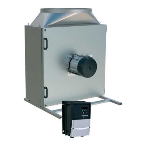
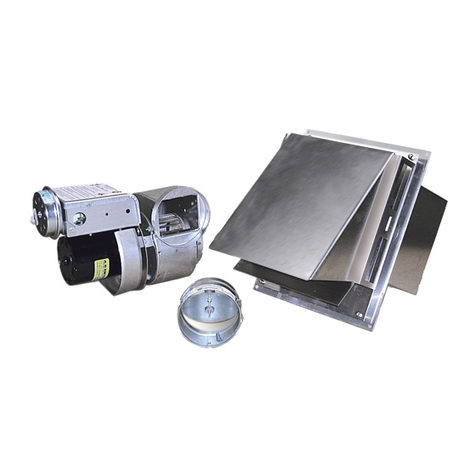
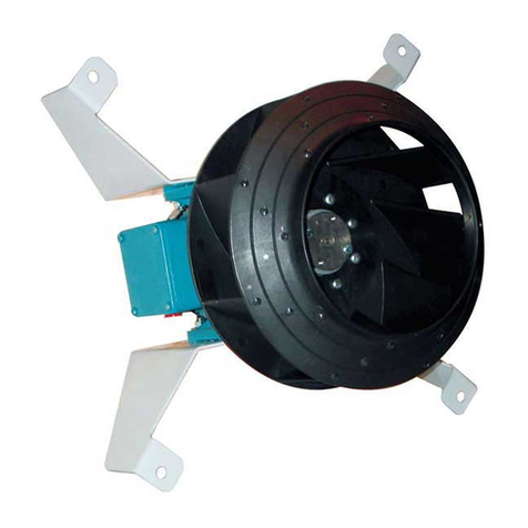
ENERVEX BESF Installation instructions

3002443 04.14 Installation & Operating Manual
USA
CAN
BESF Box Ventilator
ENERVEX Inc.
1685 Bluegrass Lakes Pkwy.
Alpharetta, GA 30004
P: 770.587.3238
F: 770.587.4731
T: 800.255.2923
www.enervex.com
Job Name:
Installer:
Installation Date:
Product Information
Mechanical Installation
Electrical Installation
Start Up and Conguration
Maintenance and Troubleshooting
........................ Chapter 1 + 2
......................... Chapter 3
............................. Chapter 4
.................. Chapter 5
...... Chapter 6
READ AND SAVE THESE INSTRUCTIONS!

2
3002443 04.14
1. Product Information
1.1 Function........................................................................................................................... 3
1.2 Components .................................................................................................................... 3
1.3 Shipping........................................................................................................................... 4
1.4 Warranty .......................................................................................................................... 4
2. Specications
2.1 Dimensions & Capacities................................................................................................. 5
3. Mechanical Installation
3.1 Positioning ....................................................................................................................... 6
3.2 Floor or Roof Mounting.................................................................................................... 6
3.3 Ceiling Mounting.............................................................................................................. 7
3.4 Connection to Duct .......................................................................................................... 7
4. Electrical Installaion
4.1 General............................................................................................................................ 8
4.2 Wiring Diagram................................................................................................................ 8
5. Startup & Conguration
5.1 System Testing ................................................................................................................ 9
5.2 Adjusting the Fan Speed ................................................................................................. 9
5.3 Adjusting the Proven Draft Switch ................................................................................... 9
6. Maintenance & Troubleshooting
6.1 Cleaning Intervals.......................................................................................................... 10
6.2 Cleaning ........................................................................................................................ 10
6.3 Troubleshooting ...............................................................................................................11
5. This unit must be grounded.
How to use this manual
This installation manual does not contain any system design
documentation. System design documentation is available from any
authorized ENERVEX representative.
Accessories, fans and variable frequency drives are not covered by
this manual. Please refer to these component’s individual manuals.
TO REDUCE THE RISK OF FIRE, ELECTRICAL SHOCK OR INJURY TO PERSONS,
OBSERVE THE FOLLOWING:
Caution: Indicates an imminent hazardous situation
which, if not avoided, may result in personal injury or
property damage.
Symbol Legend:
The following terms are used throughout this manual to bring attention
to the presence of potential hazards or to important information
concerning the product.
Danger: Indicates an imminent hazardous situation
which, if not avoided, will result in death, serious injury or
substantial property damage.
1. Use this unit in the manner intended by the manufacturer. If
you have questions, contact the manufacturer at the address or
telephone number listed on the front of the manual.
2. Before servicing or cleaning the unit, switch off at service panel
and lock service panel to prevent power from being switched on
accidentally.
3. Installationworkandelectricalwiringmustbedonebyaqualied
person(s) in accordance with applicable codes and standards.
4. Follow the appliance manufacturer’s guidelines and safety
standards such as those published by the National Fire Protection
Associations (NFPA), and the American Society for Heating,
Refrigeration and Air Conditioning Engineers (ASHRAE), and the
local code authorities.

3
3002443 04.14
1. Product Information
1.1 Function
Use ENERVEX Model BESF is a box ventilator that can be used for the movement of air in exhaust and air
supply systems where no explosive gases are present. The ventilator cannot be used for transport of
large particles. It is designed to provide a high capacity at a high static pressure. The ventilator is best
suited for indoor installations. Suitable uses include, but are not limited to: comfort ventilation, residential
kitchen ventilation, exhaust and air supply.
The exhaust temperature must be above 10°F (-12°C) but should not exceed 175°F (80°C). The ambient
temperature must be within -20°F (-30°C) and 105°F (40°C).
Construction Theventilatorhousingismadeofgalvanizedsteelandinsulatedwithberinsulation.Thecollarsare
ttedwithsiliconesealstoassureatightassembly.Themotorisadirectdrive,variablespeedclassB
insulated type. It has permanently lubricated, sealed ball bearings and is maintenance free.
Listings ENERVEX Model BESF is tested and listed to UL 705, Standard for Power Ventilators.
The BESF can be used as a component in a MCAS, Modulating Combustion Air System. The listings of
this system incorporates the BESF Box Ventilator.
Do not use with explosive gases. Do not use for transport of large particles.
1.2 Components
The box ventilator consists of the following components:
a. Housing f. Locking hinge
b. Access door g. Door handle
c. Motor h. Support legs with vibration dampers (2)
d. Centrifugal impeller i. Sheet metal screws (4)
e. Ventilator housing k. Door switch (optional)
Fig. 1

4
3002443 04.14
1.3 Shipping
Protection The ventilator is protected by a corrugated box. Do not place other products or items on top of the
box. After unpacking, the product must be handled in a way to prevent damaging the collars and the
ventilator housing.
Never operate the power venter with the access door open!
To open access door loosen screws on latch handles and raise handles.
Standard Packing The ventilator is shipped with motor installed on the access door. If other components are shipped,
these will appear on the shipment packing list.
NOTE:
All single phase fans are shipped with a capacitor and junction box connected via conduit. The capacitor
is located INSIDE the junction box. Please do not discard.
1.4 Warranty
Complete warranty conditions are available at www.enervex.com or request a copy at:
[email protected] or at tel.: 1-800.255.2923.
Fig. 2

5
3002443 04.14
2. Specications
2.1 Dimensions & Capacities
Capacity Chart
BESF 160
0 250 500 1250
0.0
0.4
0.2
0.8
0.6
1.2
1.0
1.6
1.4
2.0
1.8
750 1000
P
t
(inW.C.)
Volume (cfm)
1500
BESF 146
BESF 180
Model BESF 146 BESF 160 BESF 180
Fan Type Centrifugal Impeller (F-Wheel)
Motor Type TEFC
Voltage VAC 1x120
Amperage A 1.2 2.9 5.8
Motor Output HP 0.1 0.2 0.5
kW 0.08 0.16 0.35
RPM 1600
Weight lbs 28 38 60
kg 13 17 27
Duct Connection E in 7 8 8
mm 177 200 200
Dimensions A in 13.60 14.57 16.15
mm 345 370 410
B in 11.62 12.60 13.98
mm 295 320 355
C in 7.88 9.26 9.26
mm 200 235 235
D in 4.33 5.52 7.68
mm 110 140 195
G in 13.78 15.75 15.75
mm 350 400 400
H in 6.50 7.10 7.88
mm 165 180 200
J in 7.88 8.27 9.26
mm 200 210 235
K in 4.33 5.12 5.12
mm 110 130 130
R in 13.60 14.57 16.15
mm 345 370 410

6
3002443 04.14
3. Mechanical Installation
3.1 Positioning
The ventilator can be installed in many different positions. However, it should always be possible to open
the access door at least 80 degrees, and the locking bolts should always be accessible. Acceptable ventilator
positions are shown below in Fig. 3. Note that the ventilator motor can never point straight down as this could cause
condensation build-up around the shaft, which can shorten the product life.
Never install the power ventilator so the motor points down. This will shorten the life.
3.2 Floor or Roof Mounting
To minimize the transfer of noise and vibration the ventilator should be placed on a surface that is level, stable and
vibration-free. The ventilator does not need to be secured by any means. See Fig. 4 on page 7.Once the
installation location has been selected the support legs must be installed. For the standard position bolt holes are
pre-drilled so the legs should just be aligned and secured with the enclosed sheet metal screws.
For all other positions, the legs should be placed in a proper position and holes should be drilled prior to securing
the legs to the ventilator by means of the enclosed sheet metal screws. When placing the ventilator, make sure the
access door can open approximately 80°. See Fig. 5.
Fig. 3
Fig. 4 Fig. 5

7
3002443 04.14
3.3 Ceiling Mounting
The box ventilator can be mounted with plumber’s strap or threaded rod with nuts and washers, or it can be placed on support
legs (included). As Fig. 6 illustrates, the ventilator can be placed in virtually any position or direction, except with the motor
pointing down. When placing the venter on the support legs (1), the vibration dampers (4) should be used and secured by nuts
(2).Thesupportlegsareattachedtothebottomoftheventerusingtheenclosedsheetmetalscrews(3).Inthisconguration
the venter is typically placed on a shelf hung from a wall.
If hanging the venter from the ceiling, threaded rods should be used. Attach the support legs (1) to the bottom of the fan and
secure with the sheet metal screws (3). Do not use the vibration dampers. Instead use the holes on the top of the legs for the
threaded rods and secure these with the nuts (5).
3.4 Connection to Duct
In order to achieve optimal perfomance and energy consumption, the duct must be installed as shown in Fig. 7 and the
distances observed. If transfer of vibrations is a major concern special vibration dampening connectors (FLF) should be
installed. These are available from ENERVEX. If a duct is not connected, a safety screen (accessory), as shown in Fig. 8, must
be installed. Make sure the sizing of the ventilator takes the resulting static pressure loss into account.
Fig. 6
Fig. 7 Fig. 8

8
3002443 04.14
4. Electrical Installation
4.1 General
DANGER
Turn off electrical power before servicing. Contact with live electric components can cause shock
or death.
All electrical wiring must be in accordance with requirements of authority having jurisdiction or, in absence of such requirements,
with National Electrical Code NFPA 70 — latest edition. If an external electrical source is utilized, system must be electrically
grounded in accordance with requirements of the authority having jurisdiction or, in the absence of such requirements, with the
National Electrical Code NFPA 70 — latest edition.
The ventilators have a split capacitor motor with infinitely variable speed.
The fan speed control supplied is rated 1x120V/60 Hz and 5 Amps. It has an adjustable low voltage set point of min.
65 V +/- 5 V.
NOTICE
If any of the original wire supplied with the system must be replaced, use similar wire of the same
temperature rating. Otherwise, insulation may melt or degrade, exposing bare wire.
4.2 Wiring Diagram - BESF 146-180
Ventilator and motor specifications can be found on page 5. The ventilator can be equipped with a variable speed motor. Fig. 9
shows a typical wiring diagram for a BESF utilizing a Fan Speed Control.
Fig. 9
24V GAS VALVE
COM
TR
HOT
TH
PROVEN DRAFT
SWITCH
RED
WHITE
BLACK
GREEN
FAN
MOTOR
120/1/60
24 VAC
NOTES:
THE DISCONNECT MEANS AND CIRCUIT PROTECTION ARE TO
BE PROVIDED BY THE INSTALLER OF THIS DEVICE
1
All wiring must be in
flexible or rigid metal
conduit
LEGEND:
24 VAC
120 VAC
WEATHERPROOF BOX
N
L
FAN SPEED
CONTROL
ORANGE

9
3002443 04.14
5. Start-up and Conguration
5.1 System Testing
Before any adjustments are made to the system, follow these procedures:
1. Turn the fan ON and make sure that it is operating. Increase and decrease the speed of the fan by adjusting the fan
speed control to make sure it is operating properly.
2. Turn the fan OFF and make sure the pressure switch opens, so the power to the circuit, it controls, is disconnected.
DANGER
Check other heating appliances (water heater, furnace, fireplace etc.) for proper operation while
the ventilator is operating. Make sure no flue gases are spilling out as this can lead to carbon
monoxide poisoning.
5.2 Adjusting the Fan Speed
Start up all appliances. Use the fan speed control to set the speed of the ventilator so no back pressure is experienced
anywhere in the system. Check the system for flue gas spillage. Mark this setting on the fan speed control cover.
5.3 Adjusting the Proven Draft Switch Setting
Remove the snap-on cover from the conduit enclosure by loosening its retaining screw. Turn the slotted Adjustment Screw
clockwise to raise the set point pressure and counter clockwise to lower the set point.
Set the adjustment to its lowest position. With all appliances operating, reduce the speed of the fan to the set point, where the
appliance(s) starts to spill flue gas. Increase the speed of the fan gradually to the point where there is no more spillage. Raise
the switch’s set point so it opens. Return the fan speed to the original setting marked on the cover.
The system is now adjusted so the flue gas spillage will disconnect the heating appliance(s).
The procedure described here may not cover all Proven Draft Switches, so please review the Installation Manual for
the switch being used.

10
3002443 04.14
6. Maintenance & Troubleshooting
6.1 Cleaning Intervals
The ventilator is designed for prolonged use. It must be inspected and cleaned at least every 12 months. The need for
cleaning is dependent on the type of application and how the ventilator is operated.
6.2 Cleaning
Deposits should be removed from the impellers and the bottom of the ventilator:
1. Turn the fan off at the repair switch.
2. When the blower wheel no longer rotates, open the access door.
3. Clean the inside housing and the wheel with water containing a detergent.
4. Dry all parts with a cloth.
5. Close and secure the access door.
6. Turn the fan on.
If necessary, the blower wheel can be removed. Prior to removal, mark the position on the shaft. The placement of the wheel is
also shown on a label placed on the inside of the access door.
Do not remove the balancing weights on the impellers.
Vibration in the ventilator can be caused by a dirty impeller.
No other maintenance is required.
Fig. 10

11
3002443 04.14
Problem Probable Cause What to do
Fan is making too much noise. Ducting is too small for the volume of
the air.
Resize ducts.
Ducts/Filters are dirty/clogged. Cleanandinspectductsandlters.
Fan inlet or outlet is too close to the
customer.
Relocate duct or fan.
Fan is vibrating and making noise. Damaged during shipping or
installation.
See if blower wheel is damaged or
if motor shaft is bent. Replace if
damaged.
Dirt build-up on blower wheel. Clean wheel.
Fan and air ducts not installed with
vibration dampers.
Install vibration dampers.
Fan is not working Power is off. Switch on power to the fan.
Capacitor is not wired correctly. Rewire connection.
Fan speed control is bad. Bypass fan speed control. If fan now
operates at 100%, replace fan speed
control.
Fan is getting power, but will not
run.
Blower wheel is stuck due to dirt build-
up.
Clean blower wheel.
Fan speed control is set too low. Set fan speed control to highest setting
until fan is up to speed. Then reduce
speed.
Motor bearings have seized. (Refer to
section 1.1 “Use”.)
See that the fan is operating within its
design parameters. Replace the motor.
Motor capacitor has failed. (Refer to
section 1.1 “Use”.)
Please refer to Fig. 12 and insure
that capacitor is connected correctly.
Check amp draw with and without the
capacitor being connected. If amp
draw is the same, replace capacitor.
Fan is overheating and cycling on
and off.
Dirt build-up on blower wheel. Clean blower wheel.
Motor capacitor has failed. (Refer to
section 1.1 “Use”.)
Please refer to note in section above.
Motor windings or bearings are failing.
(Refer to section 1.1 “Use”.)
Check amp draw. If incorrect, replace
blower motor.
6.3 Troubleshooting

ENERVEX Inc.
1685 Bluegrass Lakes Pkwy.
Alpharetta, GA 30004
P: 770.587.3238
F: 770.587.4731
T: 800.255.2923
www.enervex.com
3002443 04.14
This manual suits for next models
4
Table of contents
Other ENERVEX Fan manuals

