manuals.online logo
Brands
  1. Home
  2. •
  3. Brands
  4. •
  5. ENFORCER
  6. •
  7. Door Opening System
  8. •
  9. ENFORCER SECO-LARM SD-961A-36SLQ User manual

ENFORCER SECO-LARM SD-961A-36SLQ User manual

®
The ENFORCER Illuminated Push-to-
Open Bar works with an external electric strike or maglock to
pro ide egress from a protected area. It can work in stand
-alone mode or as part of an access
control system, but also can be locked open by key. Buzzer, output timing, and LED function and
colors are also customizable.
SD-961A-36SLQ
Illuminated Push-to-Open Bar
Manual
Features:
•
Provides convenient on-door egress
•LED makes it easy to see the status
•Can be stand-alone or connected to an
access control system
•wo built-in non-latching (momentary), dual-
contact outputs (NO/NC/COM) rated at
≤5A@230VAC, adjustable 0.5~60 sec
•Dogging – standard dogging with hex key
•For 36" doors – actual length: 33
7
/
16
" (85cm)
•
Can be cut to fit smaller doors, minimum
23
5
/
8
" (60cm)
•Large LED shows red in standby and green
when triggered, but is programmable
red/green/blue by an access control panel
•Blinking LED and buzzer programmable for
relock warning
•Built-in buzzer indicate
s unlocked (selectable,
up to 92dB)
ENFORCER Illuminated Push-to-Open Bar
2SECO-LARM U.S.A., Inc.
1x
Illuminated push bar
5x
Machine screws
1x
Dogging key
1x
Keyhole cover
2x
Self
-
stick wiring
anchors
1x
Manual
Overview:
Specifications Parts List:
Specifications:
Parts List:
Please read the manual carefully before beginning installation.
1. Hold the push bar unit on the door at the desired
height, ensuring that there is sufficient space on
both ends as noted below. With a pencil, mark
the lower edge of the base and the edge of the
base end cap on the latch side of the door.
OTES:
•Leave at least 9/16" (1.5cm)
space between the door edges
and both ends of the base.
•Level with a bubble level.
•he height of the push bar from
the floor may be subject to
local regulations.
•Usually, the bar is centered but for wider
doors it can be closer to the latch side.
2. Remove the two screws from each of the push
bar end caps and remove the end caps.
If you need to cut the push bar to fit a door narrower
than 36" (91.4cm), skip to step 4.
3. For doors at least 36" (91.4cm) wide, mount the
bar to the door. Using the lines drawn in step 1,
hold the base in place and mark 4 mounting
screw holes (and the wiring hole if wiring runs
through a hollow door using an electric transfer
hinge). Drill holes, making sure not to go all the
way through the door and mount on the door.
P U S H TO E X I T
Installation:
33
7
/
16
" (850mm)
2
3
/
8
"
(61mm)
8
1
/
4
" (210mm)
1" (25mm)
*Dogging key
shown in use
(normally removed)
Cutaway View
LED Indicator
Push bar Dogging key*
Base end
cap (x2)
PCB
Spring loaded push
bar bracket (x2)
Push bar end
cap (x2)
2
3
/
8
"
(61mm)
Punchout for
Exposed wiring (x2)
Operating voltage 12~24 VDC
Power consumption 180mA@12VDC, 140mA@24VDC (max.)
Contact load ≤5A@230VAC
Outputs NO/NC/COM x2
rigger duration 0.5~60 seconds (adjustable) or dogged open
Buzzer Up to 92dB (adjustable)
LED
Indicator
Colors Stand-alone red/green, Controlled red/green/blue
Size 8
1
/
4
"x1" (210x25 mm)
Door width 36" (91.4cm), minimum 23
5
/
8
" (60cm)
Operating temperature 32°~150° F (0°~70° C)
Dimensions 33
7
/
16
"x2
3
/
8
"x2
3
/
8
" (850x61x61 mm)
Weight 4-lb 10-oz (2.1kg)
≥
9
/
16
"
(1.5cm)
ENFORCER Illuminated Push-to-Open Bar
SECO-LARM U.S.A., Inc. 3
Installation (Continued):
OTE: he wiring connection is normally on the
hinged side of the door.
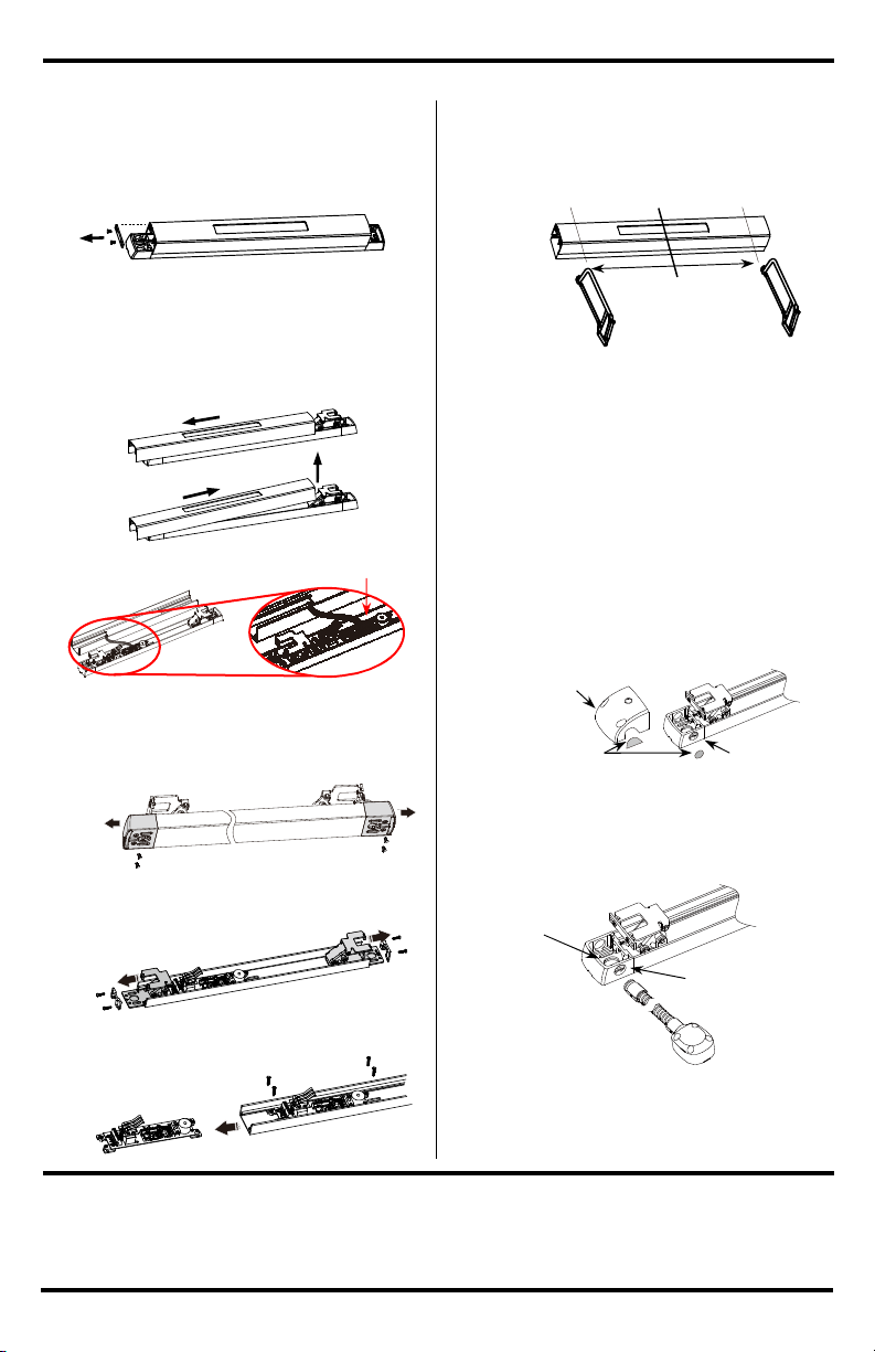
4. Remove the mounting bracket from one end of
the push bar.
5. Taking care not to damage the LED wiring
harness, slide the push bar in the direction of
the removed endplate until it is free of the
opposite push bar bracket, lift the free end,
and slide in the other direction until it is free.
6. Unplug the LED cable from the PCB.
If you do not need to cut the push bar, skip to step 8.
7. o cut the push bar to fit a narrow door:
a. Unscrew and remove both base end caps.
b. Remove the screws and slide the two push
bar brackets off the base.
c. Remove the screws and slide the circuit
board off the base.
d.
d. Measure the door width and subtract from
36" (91.4cm). Divide the result in half and
carefully mark the base and push bar to cut
an equal amount from each end of both.
OTES:
•he minimum cut length is 235/8" (60cm).
•Both push bar and base must be the same
length and the cuts must be at a 90° angle.
e. Replace the circuit board, push bar brackets,
and base end caps (reversing steps 7a~7d,).
Mount the base to the door as in step 3.
8. For exposed wiring or an armored cable, punch
out the scored wiring hole on the side of the
base end cap and the scored piece from the
corresponding push bar end cap.
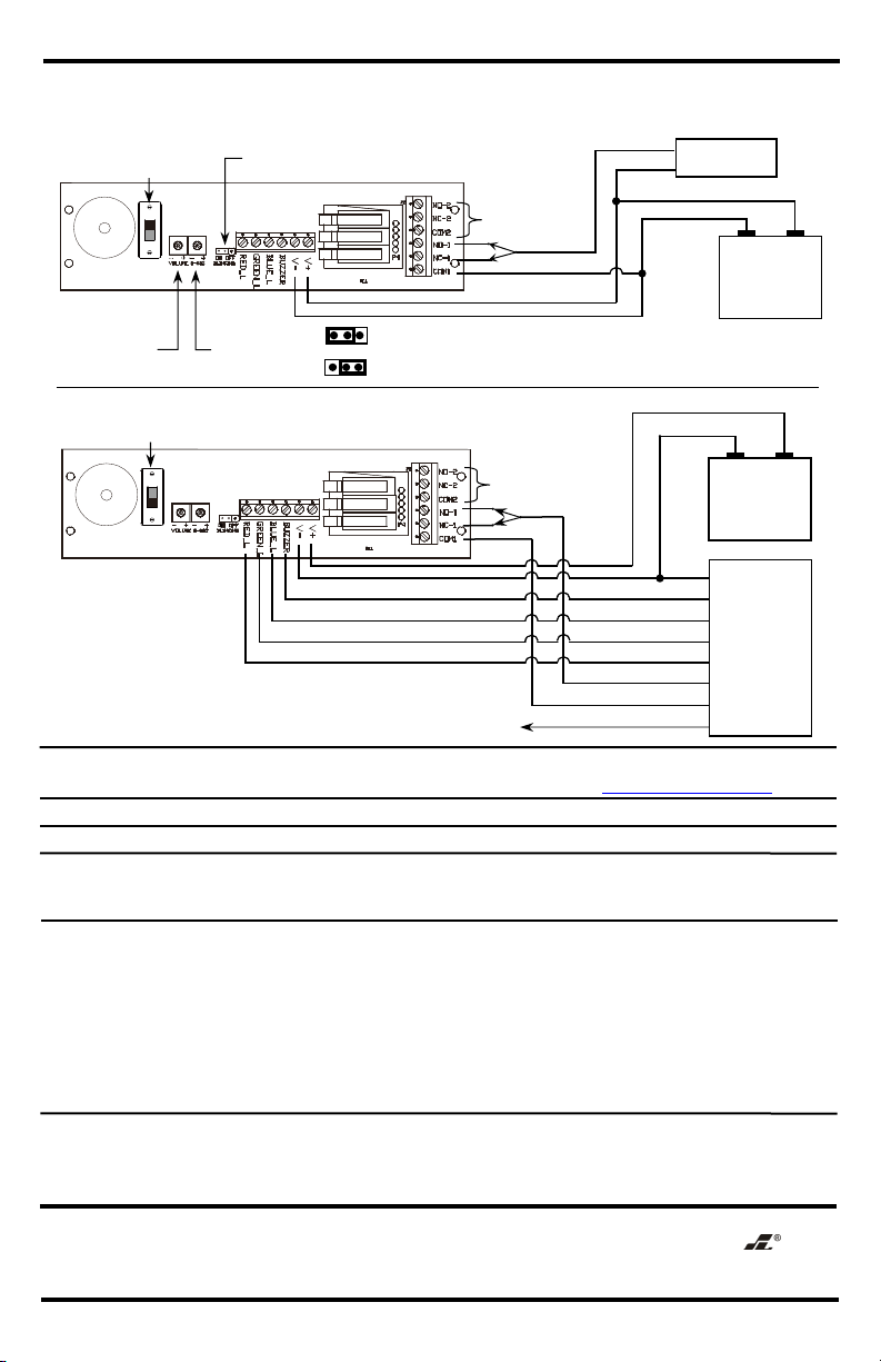
9. Run the wires through the base cap hole and
connect to the terminals (see Sample
Installations and Wiring Diagrams, pg. 4). If
using an armored cable, attach the cable.
10. Plug the LED wiring harness back in to the PCB,
replace the push bar, and reattach the end caps,
reversing steps 4~6.
PUSHTO
EXIT
Concealed wiring
hole (hollow door)
Exposed wiring or
armored cable hole
Wiring
punch outs
Base end cap
Bar end cap
Centerline



Included with the push bar is a
dogging
key. o lock the push bar closed (to allow two
-
way, uncontrolled
access to the protected area), remove the keyhole
cover, push the bar in all the way, and turn the bolt with the
dogging key. o release the bar, turn the bolt to its original position.
Lock
ing the Bar
Open
:
ENFORCER Illuminated Push-to-Open Bar
4SECO-LARM U.S.A., Inc.
Sample
Applications
and Wiring Diagrams:
SECO-LARM
®
U.S.A., Inc.
16842 Millikan Avenue, Irvine, CA 92606
Website:
www.seco
-
larm.com
Phone: (949) 261
-
2999 | (800) 662
-
0800
Email: sales@seco
-
larm.com
PI SW2
MI_SD-961A-36SLQ_210329.docx
OTICE
:
he SECO
-
LARM policy is one of continual development and improvement. For that
reason, SECO
-
LARM
reserves the right to change specifications without notice. SECO-LARM is also not responsible for misprints. All t
rademarks
are the property of SECO-LARM U.S.A., Inc. or their respective owners. Copyright © 2021 SECO-LARM U.S.A., Inc. All
rights reserved.
WARRA TY:
his SECO
-
LARM product is warranted against defects in material and workmanship while
used in normal
service for one (1) year from the date of sale to the original customer. SECO-LA
RM’s obligation is limited to the repair or
replacement of any defective part if the unit is returned, transportation prepaid, to SECO-LARM.
his Warranty is void if
damage is caused by or attributed to acts of God, physical or electrical misuse or abuse,
neglect, repair or alteration,
improper or abnormal usage, or faulty installation, or if for any other reason SECO-
LARM determines that such equipment
is not operating properly as a result of causes other than defects in material and workmanship. he sole
obligation of
SECO-LARM and the purchaser’s exclusive remedy, shall be limited to the replacement or repair only, at SECO-LARM
’s
option. In no event shall SECO-
LARM be liable for any special, collateral, incidental, or consequential personal or property
damage of any kind to the purchaser or anyone else.
IMPORTA T:
It i
s the responsibility of the installer and/or end
-
user customer to ensure the
Illuminated Push
-
to
-
Open Bar
meets all local regulations regarding the use of push bars for access security, including: s
uitability for doors accessed by
disabled persons and suitability for fire doors (the push bar is not fire-rated).
WAR I G:
he push bar is not weatherproof. Do not mount on exterior surfaces or where exposed to rain
.
IMPORTA T:
he height at
which the push bar is mounted
may be subject to local regulations.
California Proposition 65 Warning
:
hese
products may contain chemicals which are known to the State of California to
Stand-Alone Installation (Factory Default)
Security System Installation
Switch up for
stand-alone mode
Output duration
(0.5~60s,
default = 60s)
Buzzer v
olume
control
(default = min.)
Door Lock
–
+
12~24VDC
Power Supply
–
+
LED/Buzzer warning
mode jumper*
or
Switch down for
controlled mode
or
–
+
12~24VDC
Power supply
Auxiliary
output
†
–
Buzzer output
Blue ou
t
put
Auxiliary
output
†
†
Light, strobe, siren, alarm, etc.
Green out
put
Red output
Input (NO/NC
COM
o electric lock NO/NC
Control panel
Buzzer volume, output
duration, LED settings are
controlled by the alarm
control system.
Buzzer and LED colors are
all negative triggers.
*
he LED can be set to blink while the buzzer sounds
intermittently during the last 6 seconds of the output
as a warning that the door is about to relock.
OFF
ON
(default)
California Proposition 65 Warning
:
hese
products may contain chemicals which are known to the State of California to
cause cancer and birth defects or other reproductive harm. For more information, go to www.P65Warnings.ca.gov.

Other ENFORCER Door Opening System manuals

ENFORCER Enforcer E-942FC-600SQ User manual

ENFORCER

ENFORCER Enforcer E-942FC-600SQ User manual

ENFORCER SD-991A-E1Q User manual

ENFORCER

ENFORCER SD-991A-E1Q User manual

ENFORCER SM-4201-LQ User manual

ENFORCER

ENFORCER SM-4201-LQ User manual

ENFORCER SM-226LQ User manual

ENFORCER

ENFORCER SM-226LQ User manual

ENFORCER SD-961A-36GQ User manual

ENFORCER

ENFORCER SD-961A-36GQ User manual

ENFORCER Enforcer E-942FC-1K3SQ User manual

ENFORCER

ENFORCER Enforcer E-942FC-1K3SQ User manual

ENFORCER Enforcer Access SD-962AR-36A User manual

ENFORCER

ENFORCER Enforcer Access SD-962AR-36A User manual

ENFORCER SD-962AR-36G User manual

ENFORCER

ENFORCER SD-962AR-36G User manual

ENFORCER SM-4302-LQ/W User manual

ENFORCER

ENFORCER SM-4302-LQ/W User manual

Popular Door Opening System manuals by other brands

Lamp AZ-GD231 installation instructions

Lamp

Lamp AZ-GD231 installation instructions

GAL MOVFR How to connect

GAL

GAL MOVFR How to connect

BGates LT Installation and user manual

BGates

BGates LT Installation and user manual

Beninca ZED24 manual

Beninca

Beninca ZED24 manual

Assa Abloy Norton 9540 Series installation instructions

Assa Abloy

Assa Abloy Norton 9540 Series installation instructions

Henderson HUSKY 100 Fitting instructions

Henderson

Henderson HUSKY 100 Fitting instructions

Woelm HELM GT-L 50 installation instructions

Woelm

Woelm HELM GT-L 50 installation instructions

BFT FR95 Series manual

BFT

BFT FR95 Series manual

CAME FLY Series manual

CAME

CAME FLY Series manual

Assa Abloy Corbin Russwin PED5400 FE installation instructions

Assa Abloy

Assa Abloy Corbin Russwin PED5400 FE installation instructions

DOM GUARD Assembly and operating instructions

DOM

DOM GUARD Assembly and operating instructions

CDVI IPV1 manual

CDVI

CDVI IPV1 manual

GFA VR/TF2E instructions

GFA

GFA VR/TF2E instructions

Detex AO19-2 user manual

Detex

Detex AO19-2 user manual

Dormakaba ED50 installation instructions

Dormakaba

Dormakaba ED50 installation instructions

PDQ 6300 installation instructions

PDQ

PDQ 6300 installation instructions

Eco SR TS-61 B Assembly instruction

Eco

Eco SR TS-61 B Assembly instruction

Overhead door STANLEY quick start guide

Overhead door

Overhead door STANLEY quick start guide

manuals.online logo
manuals.online logoBrands
  • About & Mission
  • Contact us
  • Privacy Policy
  • Terms and Conditions

Copyright 2025 Manuals.Online. All Rights Reserved.