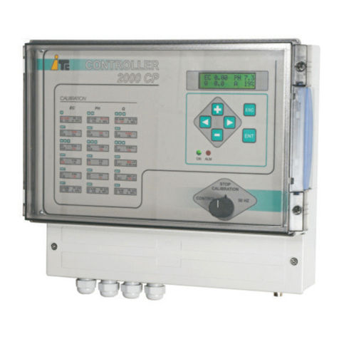
ITC VISIONS 3000 User manual

ENGLISH
WATER CONTROLLER 3000


WATER CONTROLLER 3000
INDEX
1. GENERALDESCRIPTION
1.1 Equipment description 4
1.2 Console description 4
1.3 Menu scheme 5
1.4 Fertirrigation menus 6
1.5 RS-485 communication port 6
2. INSTALLATION
2.1 Water Controller 3000 installation 7
2.2 Hydraulic scheme 8
2.3 Electric scheme 9
3. CONFIGURATION
3.1 SET UP 10
3.2 Irrigation pumps set up 10
3.3 Filters set up 11
3.4 Mixers set up 11
3.5 External activation of an irrigation program 13
3.6 Watering Factor 13
3.7 Irrigation program 13
3.8 Fertirrigation 15
3.8.1 Calibration menu 15
3.8.2Alarms 18
3.8.3Advanced control options 20
3.8.4Advanced Set Up options 23
3.8.5 Control mode 24
4. PROGRAMATION
4.1 Examples: Irrigation program 25
4.2 Example: Fertirrigation program 27
4.3 Errors regarding the programming 27
5. OPERATION
5.1 Switch functions 28
5.2 Remote stop 28
5.3 Manual activation of irrigation program 29
5.4 Stop an irrigation program 29
6. TECHNICAL FEATURES 30
7. MAINTENANCE 32
EC declaration of conformity 34
Warranty 36
USER'S MANUAL
3

1 GENERAL DESCRIPTION
Simplicity in irrigation control.
Control of 96 blocks through 50 irrigation programs with 15 daily starts up. Easy and intuitive programming allows the
user to avoid schedule problems such as valve overlaps. Automatic filters cleaning and pumps starter function are
available, as well as the Watering Factor to modify the duration of all the irrigation programs.
Precision in dosing.
Fertigation control by means of 48 programs, which can be linked to the watering programs. The PIQ algorithm
developed by ITC, can control the addition of 6 different products proportionally to water flow and simultaneously
according to EC and pH set points.
1. GENERAL DESCRIPTION
1.1 EQUIPMENT DESCRIPTION
WATER CONTROLLER 3000
SWITCH
RUN W+F : Irrigation + Fertirrigation
RUN W: Irrigation (calibration)
STOP (calibration)
CONSOLE
DOSING
PUMPS
OUTPUTS
SENSOR
INPUTS
OUTPUTS
FIELD ELECTROVALVES
PUMPS
FILTERS
1.2 CONSOLE DESCRIPTION
ESC
ENT
Start:12:45
12:55Tu (AC)
00:45
PH 7.5 EC 1.5mS
250m3h
Q5.4bar
MW09F02
Start time and
time left to finish
the program
EC, pH, Q (flow) and P, readings
flashing when alarm on
Day identification: A/B and C/D/E
C2 Communication with module 2 is lost. C2 flashes.
Cleaning Filters
INPUTS
IRRIGATION ACTIVATION
FILTERS CLEANING
MAIN SCREEN DESCRIPTION
DESCRIPTION OF THE KEYBOARD
Active irrigation and fertirrigation programs
+ / - to increase / decrease a value.
< / > menús broser
ESC To finish a menu without saving
ENT To enter a menu and to validate a value
Watering factor >100% ( ), <100% ( )
(M) Manual activation of the program
Filters cleaning
USER'S MANUAL
WATER CONTROLLER 3000
4

1.3 MENU SCHEME
1. GENERAL DESCRIPTION.
60" without pressing any key
USER'S MANUAL
Start:12:45
12:55Tu (AC)
00:45
PH 7.5 EC 1.5mS
250m3h
Q5.4bar
W09
Q
EC
PH
250
1.05
7.6
AF02
5.4bar
B
1
2
3
4
5
6
EC 31%
P 50%
P 100%
% 86%
M 50%
PH 93%
mS
m3h
ENT
250m3h
Q5.4bar
ENT ESC
F02
ENT
MAN
Start:12:45 00:45
Tu Th
CONF
Mo We Fr Sa Su
PROG
ESC
STOP
ESC
W09 F02
250m3h
Q5.4bar
Start:12:45 00:45
Tu Th
CONF
Mo We Fr Sa Su
PROG
STOP
W09 F02
MAN
250m3h
Q5.4bar
MAN
Start:12:45 00:45
Tu Th
01 02 05 06 08 22
CONF
Mo We Fr Sa Su
PROG
STOP
W09 F02
ESC
Manual activation menu
Programation menu
250m3h
Q5.4bar
MAN
Start:12:45 00:45
Tu Th
Mo We Fr Sa Su
CONF
PROG
STOP
W09 F02
250m3h
Q5.4bar
MAN
Start:12:45 00:45
Tu Th
CONF
Mo We Fr Sa Su
PROG
W09 F02
Configuration menu
Stop Program menu
STOP
MAIN SCREEN
IRRIGATION FERTIRRIGACIÓN
ENT
ESC
01 02 05 06 08 22
01 02 05 06 08 22
01 02 05 06 08 22
01 02 05 06 08 22
0 2 4 6 8 10
12 14 16 18 20 22
01 02 05 09
03 04 06 10
Program without fertirrigation
Program with fertirrigation
Date: 12.07.11
Next day
DAILY PLANNING
ESC
Q
EC
PH
250
1.05
7.6
A F02
5.4bar
B
CAL
PROG
ALM
CONT
HIST
AUX
mS
m3h
ENT
ENT
ESC
Calibration menu
ENT
Q
EC
PH
250
1.05
7.6
A F02
5.4bar
B
CAL
PROG
ALM
CONT
HIST
AUX
mS
m3h
ESC
Control menu
ENT
Q
EC
PH
250
1.05
7.6
A F02
5.4bar
B
CAL
PROG
ALM
CONT
HIST
mS
m3h
AUX
Auxiliar menu
Program menu
Alarm menu
History menu
ENT
WATER CONTROLLER 3000
5

1.4. FERTIRRIGATION MENUS
Q
EC
PH
250
1.05
7.6
A F02
5.4bar
B
CAL
PROG
ALM
CONT
HIST
AUX
mS
m3h
Q
EC
PH
250
1.05
7.6
A F02
5.4bar
B
12
EC 31% % 86%
mS
m3h
Readings Screen with
Outputs Display
Readings Screen with
Menus Display
Q
EC
PH
250
1.05
7.6
A F02
5.4bar
B
12
EC 31% % 86%
mS
m3h
Water Flow Reading
PH Reading
EC Reading
Pressure Reading
Active Programm
EC Control Channel
PH Control Channel
Output Control Number
Control mode
on the output
Output Value in percentage
1.5. RS-485 COMMUNICATION PORT
RS-485 port
Connection of a GATE, for a real time evolution of the readings of the sensors and the regulation of the dosing pumps.
RS-485
WATER CONTROLLER 3000
USER'S MANUAL
1. GENERAL DESCRIPTION.
GATE
6

2. INSTALLATION
2.1 WATER CONTROLLER 3000 INSTALLATION
WATER 3000 module
SMART DROP TECHNOLOGY
RCP/PCPM 3500
ESC
ENT
CONTROL
STOP
CONTROLLER 3000
TRANSPARENT
FORAT
CALIBRACION
STOP
CONTROL
WATER 3000 module
SMART DROP TECHNOLOGY
WATER 3000 module
SMART DROP TECHNOLOGY
WATER 3000 module
SMART DROP TECHNOLOGY
Console Module 1 Module 2 Module 3 Module 4
Output 1 ... 24 Output 25 ... 48 Output 49 ... 72 Output 73 ... 96
Module 1: Output 1...6 Output 7...12 Output 13...18 Output 19...24
CONNECTIONS
MODULE CONFIGURATION
1230Vac
2Common 24Vac outputs
324Vac outputs
Module 2: Output 25...30 Output 31...36 Output 37...72 Output 43...48
Module 3: Output 49...54 Output 55...60 Output 61...66 Output 67...72
Module 4: Output 73...78 Output 79...84 Output 85...90 Output 91...96
4Input 2:
Input 1:
RS-485: Module-module and módule -Controller 3000 communication.
5
6
Module 1: Cleaning filters (switch). Activated when contact closed.
Module 2: External activation of irrigation program. Close contact activation.
Module,3, 4: N.d.
Module 1: Irrigation Start / Stop. Activated when contact closed.
Module 2: External activation of irrigation program. Close contact activation.
Module 3, 4: N.d.
A B
C3000 Mod1 Mod2 Mod3 Mod4
AB AB AB ABAB AB AB AB
24561 3
2
1 3 2
1 3
USER'S MANUAL
Module 1 Module 2 Module 3 Module 4
WATER CONTROLLER 3000
2. INSTALLATION
7

2.2 HYDRAULIC SCHEME
WATER CONTROLLER 3000
USER'S MANUAL
2. INSTALLATION
OFF
ON
N
L
MOTOR
VENT
OFF
ON
N
L
MOTOR
VENT
OFF
ON
N
L
MOTOR
VENT
OFF
ON
N
L
MOTOR
VENT
FREQUENCY VARIATOR - INVERTER
INJECTION PIPE: 0 - 2 meters
Flow Inner
Diameter
DOSITEC: 0 -10 l/h 4 mm
DOSTEC: 0 - 80 l/h 6 mm
0 - 300 l/h 15 mm
0 -1000 l/h 32 mm
INJECTION PIPE: 0 - 10 meters
Flow Inner
Diameter
DOSITEC: 0 -10 l/h 4 mm
DOSTEC: 0 - 25 l/h 6 mm
0 - 80 l/h 15 mm
0 - 200 l/h 20 mm
0 - 300 l/h 25 mm
0 - 500 l/h 32 mm
0 - 750 l/h 50 mm
0 - 1000 l/h 65 mm
SUCTION PIPE: 0 - 2 meters
Flow Inner
diameter
DOSITEC: 0 -10 l/h 4 mm
DOSTEC: 0 - 50 l/h 6 mm
0 - 300 l/h 15 mm
0 -1000 l/h 40 mm
SUCTION PIPE
Flow Inner
Diameter
DOSITEC: 0 -10 l/h 4 mm
DOSTEC: 0 - 25 l/h 6 mm
0 - 100 l/h 15 mm
0 - 200 l/h 20 mm
0 - 300 l/h 25 mm
0 - 500 l/h 32 mm
0 - 750 l/h 40 mm
0 - 1000 l/h 70 mm
: 0 - 5 meters
Small filter
Elbows, Mixer
collector static
Water meter
...
Filter 100 mesh
EC PH
P
Q
MIXING
ELEMENT
20 x Diámetro 5 x Diámetro
DOSITEC
WATER 3000 module
SMART DROP TECHNOLOGY
8

2.3 ELECTRIC SCHEME
TERMINAL CONNECTION
WATER CONTROLLER 3000
USER'S MANUAL
2. INSTALLATION
LALM
pH ALM
EC ALM
Q
ALM
P
P+P- B
A
NOUT
24v RS-485
123456 7 8910 11 12 13 14 1516 17 1819 20 21 22 23
WATER CONTROLLER 3000-6/24
WATER CONTROLLER 3000-2/24
230 V AC
ALARMS
230V
OFF
ON
N
L
MOTOR
VENT
EC PH
17 9
18
112 13
111
P
Q
910
1
2
230V
OFF
ON
N
L
MOTOR
VENT
230V
OFF
ON
N
L
MOTOR
VENT
FREQUENCY REGULATORS -
INVERTERS
4
910
9
11
Q
EC
12 P
3x1,5mm
+1,5mm
56789
78
4
V1
W1
U1
230 V
230V
N
L
MOTOR
VENT
230V
3x1,5mm
+1,5mm
2x1,5mm
+1,5mm
24V AC
VENT.
Power 230 V AC +/- 20%, 50/60Hz
Alarm outputs. Relay outputs NO, 24V AC-1A máx
RS-485 output, for connection to a Gate.
Output 4-20 mA, nº1 (5 pins connector)
Output 4-20 mA, nº2 (5 pins connector)
Output 4-20 mA, nº3 (5 pins connector)
Output 4-20 mA, nº4 (5 pins connector)
Output 4-20 mA, nº5 (5 pins connector)
1Output 4-20 mA, nº6 (5 pins connector)
Input for flowmeter (3 pins connector)
Input for EC sensor (4 pins connector)
Input for pressure transmitter
Input for pH sensor (connector BNC)
24 Outputs 24Vac
Input 1 and 2
RS-485
2
3
4
5
6
7
8
9
10
11
12
13
DOSITEC
9
6
5
3
14
15
16
WATER 3000 module
SMART DROP TECHNOLOGY
230 V AC
1
14 15
16
13 PH
9

3. CONFIGURATION.
3.2. IRRIGATION PUMPS SETUP
PUMPS menu to configure pump outputs
Use “<” / “>” to navigate the menu. Press ENT to save and ESC for not saving.
OUTP: select outputs asing to pumps.
STARTING DELAY: delay time between the activation of two pumps to be activated at the same time.
ENT
Start:12:45
12:55Tu (AC)
00:45
PH 7.5 EC 1.5mS
250m3h
Q5.4bar
W09 F02 250m3h
Q5.4bar
MAN
Start:12:45 00:45
Tu Th
01 02 05 06 08 10 25 26
45 46 48
CONF
Mo We Fr Sa Su
PROG
STOP
W09 F02
ENT
ENT ENT
3.1. SET UP
SET UP menu
Use “<” / “>” to navigate menus and ENT to access selected submenu.
1.- Language: selects language for names of the days
2.- Date and time: modifies date and time
3.- PROGRAMS: number of programs to use (1-50)
4.- MODULES: number of Water 3000 modules installed (1-4).
5.- Reset time: when all the not activated programs are reset
CONFIG
PUMPS
FILTERS
WATERING FACTOR
SET UP
CONFIG
PUMPS
ENT
PUMPS
OUTP:
STARTING DELAY: 03 s
01
250m3h
Q5.4bar
Start:12:45 00:45
Tu Th
Mo We Fr Sa Su
PROG
STOP
W09 F02
CONF
MAN
01 02 05 06 08 10 25 26
45 46 48
Top amount of 6 outputs activated at the same time for module. If more than 6 outputs are
activated then lowest number of the outputs have higher priority.
USER'S MANUAL
WATER CONTROLLER 3000
3. CONFIGURATION
CONFIG
FILTERS
MIXERS
EXPRESS PROGRAM
WATERING FACTOR
SET UP
CONFIG
PUMPS
CONFIG
PUMPS
SET UP
MIXERS
WATERING FACTOR
FILTERS
EXPRESS PROGRAM
SET UP
06.10.2012 10:00
PROGRAMS: 50
MODULES: 1
RESET TIME: 00:00
ENG
10

3. CONFIGURATION.
3.3. FILTERS SETUP
FILTERS menu
1.- STOP WATERING: YES: stops irrigation while filters are cleaned.
NO: irrigation continues while filters are cleaned.
2.- WHILE WATERING: YES: cleans filters ONLY if there is irrigation.
NO: cleans the filters no matter if there is irrigation or not.
3.- OUT: outputs assign to filters (0-6).
4.- FREQ: Frecuency in hours:minutes to clean filters. If FREQ = 00:00, it will only clean when it is ordered through
the input of cleaning filters (Input2).
5.- CLEAN: duration of the cleaning in seconds.
6.- DELAY: delay time when activating two filters at the same time.
7.- ADD OUT: more outputs activated when a filters cleaning starts.
Use “<” / “>” to navigate the menu. Press ENT to save and ESC for not saving.
USER'S MANUAL
WATER CONTROLLER 3000
3.4. MIXERS
Mixers are linked to the fertirrigation program pumps.
MIXERS menu
Number of the dosing pump
Output of the mixer
Activation mode
Time on (minutes)
Frequency
Use “<” / “>” to navigate the menu. Press ENT to save and ESC for not saving.
Select an output for each mixer, each output will be linked to the dosing pump.
CONFIG
PUMPS
FILTERS
MIXERS
EXPRESS PROGRAM
WATERING FACTOR
SET UP
CONFIG
PUMPS
CONFIG
FILTERS
PUMPS
EXPRESS PROGRAM
WATERING FACTOR
SETUP
MIXERS ENT
MIXERS
1. -- - - - - - - -: - -
2. 12 MAN - - - -: - -
3. 15 PRE 01 - -: - -
4. 16 CON - - - -: - -
5. 17 DIS 01 00:10
6. -- - - - - - - -: - -
CONFIG
PUMPS
FILTERS
MIXERS
EXPRESS PROGRAM
WATERING FACTOR
SET UP
CONFIG
PUMPS
CONFIG
FILTERS
PUMPS
MIXERS
EXPRESS PROGRAM
WATERING FACTOR
SETUP
ENT
FILTER CLEANING
STOP WATERING: NO
WHILE WATERING: YES
OUT:
FREQ.: 00:00
CLEAN: 60 s
DELAY: 30 s
ADD OUT: _ _ +-:00:00
01
11

3. CONFIGURATION.
USER'S MANUAL
WATER CONTROLLER 3000
Activation mode of a mixer
Manual (MAN): It only activates if it is activated in the irrigation program. It´s not linked to the fertirrigation program.
Previous fertirrigation (PRE): if the fertirrigation program activates the pump linked to the mixer, in the pre irrigation
time the mixers will be activated the time programmed. If the time of the mixer is higher than the pre irrigation time,
mixer working time will overlap with the fertirrigation time.
Continuous (CON): if the fertirrigation program activates the dosing pump linked to the mixer, the mixer will be activated
in pre irrigation time and irrigation time.
Discontinuous (DIS): if the fertirrigation program activates the dosing pump linked to the mixer, the mixer will be
activated in the pre irrigation and irrigation time in a discontinuous working time. It will depend on the time (minutes),
and frequency (hh:mm) programmed.
NOTE: In the post irrigation time, all the mixers are off.
MIXERS
1. -- - - - - - - -: - -
2. 12 MAN - - - -: - -
3. 15 PRE 01 - -: - -
4. 16 CON - - - -: - -
5. 17 DIS 01 00:10
6. -- - - - - - - -: - -
3.5. EXTERNAL ACTIVATION OF AN IRRIGATION PROGRAM
For an external activation of an irrigation program it´s required to use the inputs of the module 2. One program for each
input.
CONFIG
PUMPS
FILTERS
MIXERS
EXPRESS PROGRAM
WATERING FACTOR
SET UP
CONFIG
PUMPS
ENT
CONFIG
FILTERS
MIXERS
EXPRESS PROGRAM
PUMPS
SET UP
WATERING FACTOR
EXPRESS PROGRAM
INPUT 1:
INPUT 2: 10
05
WATER 3000 module
SMART DROP TECHNOLOGY
RCP/PCPM 3500
ESC
ENT
CONTROL
STOP
CONTROLLER 3000
TRANSPARENT
FORAT
CALIBRACION
STOP
CONTROL
WATER 3000 module
SMART DROP TECHNOLOGY
WATER 3000 module
SMART DROP TECHNOLOGY
WATER 3000 module
SMART DROP TECHNOLOGY
Console Module 1 Module 2 Module 3 Module 4
Out 1 ... 24 Out 25 ... 48 Out 49 ... 72 Out 73 ... 96
2
1 3 2
1 3
In this example, when activating input 1, irrigation program 5 is activated.
12

3. CONFIGURATION.
USER'S MANUAL
3. ATERING FACTOR6. W
WATERING FACTOR menu allows to increase or decrease proportionally all the irrigation time of all the programs.
Pre-irrigation time and post-irrigation time are not afected by watering factor.
Use “<” / “>” to navigate the menu. Press ENT to save and ESC for not saving.
CONFIG
PUMPS
FILTERS
MIXERS
EXPRESS PROGRAM
WATERING FACTOR
SET UP
CONFIG
PUMPS
ENT
CONFIG
FILTERS
MIXERS
EXPRESS PROGRAM
PUMPS
SET UP
WATERING FACTOR
WATERING FACTOR: 100%
ENT
250m3h
Q5.4bar
MAN
Start:12:45 00:45
Tu Th
01 02 05 06 08 10 25 26
27 32 33 52 55 58 60 72
CONF
Mo We Fr Sa Su
81 82 83 84 85
PROG
STOP
W09 F02
ENT
ENT
250m3h
Q5.4bar
Start:12:45 00:45
Tu Th
Mo We Fr Sa Su
STOP
W09 F02
PROG
CONF
MAN
01 02 05 06 08 10 25 26
27 32 33 52 55 58 60 72
81 82 83 84 85
SAVE AS
M V S D x1 x2 x3
STA: 00:00 TIME: 00:00
15 FERT:02 05
PROG: 09
L
MJ
01 02 05 06 08 10 25 26
27 32 33 52 55 58 60 72
81 82 83 84 85
SAVE AS
M V S D x1 x2 x3
STA: 00:00 TIME: 00:00
15 FERT:02 05
PROG: 10
L
MJ
01 02 05 06 08 10 25 26
27 32 33 52 55 58 60 72
81 82 83 84 85
Start:12:45
12:55Tu (AC)
00:45
PH 7.5 EC 1.5mS
250m3h
Q5.4bar
W09 F02
B C
2011
1
NOV
A E
A D
2011
2
NOV
B C
B E
2011
3
NOV
A D
A C
2011
4
NOV
B E
Start:12:45
12:55 Ma (AE)
00:45
PH 7.5 EC 1.5mS
250m3h
Q5.4bar
W09 F02
WATER CONTROLLER 3000
3.7. IRRIGATION PROGRAM
PROGRAMATION menu.
1.- PROG: To go to a program using + or -.
2.- SAVE AS: Duplicates the program (New program will not be saved if ENT is not used)
3.- Irrigation days setup
M T W T F S S, weekly irrigation days, selectables with “+” and “-”.
x1: daily
x2: every two days (A/B).
x3: every three days (C/D/E)
For irrigation programs every two days (x2) or for irrigation programs every three days (x3), Water 3000 classifies the
days as A/B and C/D/E.
Use “<” / “>” to navigate the menu. Press ENT to save and ESC for not saving.
13

USER'S MANUAL
WATER CONTROLLER 3000

3. CONFIGURATION.
5.- TIME: irrigation duration.
6.- Outputs to activate in the program. 6 is the maximum number of output to activate at the same time for module,
includes pumps and filters.
7.- Pre irrigation time.
8.- FERT: Fertirrigation program to activate.
9.- Post irrigation time.
4.- START: time of irrigation start
Start times screen to configure up to 15 daily start up.
Priorities of the program to start are:
1.- Start time of the program.
2.- If the program only has mixer outputs.
3.- Índex of the starting time (If it is the first starting time of the program, the second, etc...).
4.- Lowest program number.
Limit of 6 outputs activated at the same time for module. If more are activated, outputs
with lower number have priority.
When an irrigation program starts, and two or more programs should be activated,
the program with lowest number has priority.
SAVE AS
L M M J V S D x1 x2 x3
STA: 00:00 TIME: 00:00
15 FERT:02 05
START TIMES 10
01: 08:00 02: 08:30
03: 09:00 04: 09:30
05: 10:00 06: 11:25
07: 12:05 08: 12:35
START TIMES 10
09: 13:00 10: --:--
11: --:-- 12: --:--
13: --:-- 14: --:--
15: --:--
PROG: 10
01 02 05 06 08 10 25 26
27 32 33 52 55 58 60 72
81 82 83 84 85
00:00
01: 08:00
(X8)
09: 13:35
+
14

Q
EC
PH
250
1.05
7.6
A F02
5.4bar
B
14
EC 31% PH 86%
mS
m3h Q
EC
PH
250
1.05
7.6
A F02
5.4bar
B
CAL
PROG
ALM
CONT
HIST
AUX
mS
m3h
To Calibrate, set the switch to STOP
ENT
PRES
TIME
PUMP
PH
EC
Q
PRES
TIME
PH
EC
Q
PUMP
PUMP
ENT
3.8.1 CALIBRATION MENU
1- 200 L / H 120 % A
2- 10 L / H 100 % A
3- 300 L / H 120 % S
4- 50 L / H 60 % S
5- 9 L / H 100 % A
6- 2 L / H 100 % A
Dosing Pump Rated Flow
Maximum Adjustment
Analogue Control Output
Change Values by pressing +/-, press <> to scroll on the Menu, and validate the Configuration of the 2 Outputs by
pressing ENT.
Rated Flow:
Introduce the Rated Flow at 50 Hz of the dosing pump.
Leave “--“ when the Output is V.
Maximum flow in %
%<100: Introduce a percentage lower than 100 to limit the 4-20mA Output to a value lower than 20mA, for example
due to an over sized pump or when an acid too concentrated is dosed.
%>100: Only for dosing pumps with frequency variator, when this is programmed to work at frequency higher than
50Hz. For maximum Frequency of 60 Hz the maximum Adjustment will be 120%.
Type of output:
A: Analogue independent Output: for Electromagnetic Pumps (Dositec) and Pumps with Electric Motor and Frequency
Variator (Dostec).
V: Analogue Master Output for a Variator in multihead Pump with Servos: to control the Output that regulates the
speed of the Motor of a multihead Pump (MF-Multifertic) provided with Servos for the independent Adjustment of each
Head.
Only one V-type Output can be configured, and there should be an Output configured as S.
S: Analogue Output for Servos in multihead Pump, with Adjustment of the Motor by Frequency Variator (V Output)
EXAMPLES OF DOSING PUMPS CONFIGURATION
3. CONFIGURATION
Multifertic 2 heads with servos
2 Dostec 1 Dositec.
Servo
Module
300 l/h
2
Servo
Module
200 l/h
3
Inverter
1
Dositec
2 l/h
6
Dostec
200 l/h
4
Dostec
50 l/h
5
PUMP
1- ---- L / H 120 % V
2- 300 L / H 120 % S
3- 200 L / H 120 % S
4- 200 L / H 120 % A
5- 50 L / H 120 % A
6- 2 L / H 100 % A
Dostec
300 l/h
1
Dostec
300 l/h
23
Dostec
100 l/h
4
Dositec
9 l/h
5
Dositec
2 l/h
6
Dostec
200 l/h
10
PUMP
PUMP
1- 300 L / H 120 % A
2- 300 L / H 120 % A
3- 200 L / H 120 % A
4- 100 L / H 120 % A
5- 9 L / H 100 % A
6- 2 L / H 100 % A
10
10
PUMP
1- ---- L / H 120 % V
2- 300 L / H 120 % S
3- 200 L / H 120 % S
4- 100 L / H 120 % S
5- 50 L / H 120 % S
6- --- L / H ----- -
Inverter
1
Servo
Module
300 l/h
2
Servo
Module
200 l/h
3
Servo
Module
100 l/h
4
Servo
Module
50 l/h
5
4 Dostec with frequency inverter
2 Dositec. Multifertic 4 heads with
Servos in each module.
3.8.1.1 DOSING PUMPS CONFIGURATION
WATER CONTROLLER 3000
USER'S MANUAL
3.8 FERTIRRIGATION
15
3.8.1.3.1 Calibration set up

Q
EC
PH
250
1.05
7.6
A F02
5.4bar
B
14
EC 31% PH 86%
mS
m3h Q
EC
PH
250
1.05
7.6
A F02
5.4bar
B
CAL
PROG
ALM
CONT
HIST
AUX
mS
m3h
ENT
ENT
3.8.1.2 FLOWMETER CALIBRATION
PRES
TIME
PUMP
PH
EC
Q
Change Units by pressing +/- and validate by ENT:
m3h: Water Flow in m3/h
Dosage Flow in l/h
gal: Water Flow in GPM
Dosage Flow in GPH
3. CONFIGURATION
K-Factor (pulses/litre or pulses/gallon):
Please refer to Manual Instructions of Flow Meter in accordance with the type and size of the pipes where it is
installed.
Change Value by pressing +/- and validate by ENT
W.COUNTER: liters/pulse of a water counter
Q=0: time when it´s considered there is no flow.
Q
EC
PH
250
1.05
7.6
A F02
5.4bar
B
CAL
PROG
ALM
CONT
HIST
mS
m3h
AUX
ENT
Change Units by pressing +/- and
validate by pressing ENT.
CTRL. PH: ACID/ALKALINE: defines if the pH Control is executed by adding Acid (ACID) or Base (ALKALINE)
EC:1.40: defines the EC buffer used. It can be modified by pressing +/-
PH: 4 Time 60s: defines the pH Buffer and the Stabilization Time for the Sensor Calibration.
3.8.1.3.1 Calibration set up
Q
EC
PH
250
1.05
7.6
A F02
5.4bar
B
CAL
PROG
ALM
CONT
HIST
AUX
mS
m3h
Q
EC
PH
250
1.05
7.6
A F02
5.4bar
B
14
EC 31% PH 86%
mS
m3h
3.8.1.3 EC AND PH CALIBRATION
WATER CONTROLLER 3000
USER'S MANUAL
K-factor
(pulse/liter)
Diameter(Inch)
Diameter (mm)
K-factor
(pulse/gallon)
32 75 160
40 90 200
50 110 250
63 125 315 400
12 ½ 61 ¼ 3 8
1 ½ 4 10
25 12 16
78.5 9.2 2.2
45 6.6 1.3
27.4 4.3 0.74
15.7 3.6 0.52 0.27
297 35 8.2170 25 4.8
104 16.3 2.8
59.5 13.6 2.0 1
Flowmeter Burkert 8020
Flowmeter GF 2536
32 75 160
40 90 200
50 110 250
63 125 315 400
12 ½ 61 ¼ 3 8
1 ½ 4 10
25 12 16
57 12.3 2.030 7.6 1.4
18.6 5.3 0.8
15.6 4.0 0.4 0.2
214 47 7.7
113 29 5.2
71.5 20 3.0
59 15.1 1.6 0.9
K-factor
(pulse/liter)
Diameter(Inch)
Diameter (mm)
K-factor
(pulse/gallon)
CHECK
FIRMWARE
SETUP
ENT
SET UP
Kp B: 10
CTRL. PH: ACID
NUM PROG.: 1
EC: 1.40
PH: 4 TIME: 60S
Kp A: 10
Q
Units:
Qtype: HIGH
K-Factor: 2.00
m3h
Q
Units: m3h
Qtype: HIGH
K-Factor: 2.00
Q
Units: m3h
Qtype:
K-Factor: 2.00
HIGH
To configure a water counter, select LOW.
Q
Units: m3h
Qtype:
W.COUNTER: 000.0 l/p
TIME Q=0: 300s
LOW
Q
Units: m3h
Qtype: LOW
W.COUNTER:
TIME Q=0: 300S
000.0 l/p
Q
Units: m3h
Qtype: LOW
W.COUNTER:000.0 l/p
TIME Q=0: 300S
Q
Units: m3h
Qtype:
K-Factor: 2.00
HIGH
16

3.8.1.3.2. .PH SENSOR CALIBRATION
PRESS ENT. WAIT
PH CALIBRATION
SAMPLE PH = 7
ENT
PRES
TIME
EC
Q
PUMP
PH
Introduce the
Sensor in the Buffer
of pH7, press ENT
and wait
WAIT
0% 100%
PRESS ENT. WAIT
PH CALIBRATION
SAMPLE PH = 4
Introduce the
Sensor in the Buffer
pH4, and press ENT
and wait
WAIT
0% 100%
CALIBRATION SUCCES
PRESS ENT
Validate the pH Calibration by pressing ENTER.
Q
EC
PH
250
1.05
7.6
A F02
5.4bar
B
CAL
PROG
ALM
CONT
HIST
AUX
mS
m3h
ENT
PRES
TIME
PUMP
PH
EC
Q
3. CONFIGURATION
Q
EC
PH
250
1.05
7.6
A F02
5.4bar
B
14
EC 31% PH 86%
mS
m3h
Q
EC
PH
250
1.05
7.6
A F02
5.4bar
B
CAL
PROG
ALM
CONT
HIST
AUX
mS
m3h
ENT
PRES
TIME
PUMP
PH
EC
Q
PRESS ENT. WAIT
EC CALIBRATION
SAMPLE EC= 0.00
ENT
PRES
TIME
Q
PUMP
PH
Leave the Sensor on
the air, press ENT and
wait..
WAIT
0% 100%
PRESS ENT. WAIT
PH CALIBRATION
SAMPLE EC = 1. 40
Introduce the Sensor in the
Buffer of 1.40mS, press
ENT and wait.
WAIT
0% 100%
CALIBRATION SUCCES
PRESS ENT
Validate the EC Calibration by pressing ENTER.
EC
3.8.1.3.3 EC SENSOR CALIBRATION.
Q
EC
PH
250
1.05
7.6
A F02
5.4bar
B
14
EC 31% PH 86%
mS
m3h
WATER CONTROLLER 3000
USER'S MANUAL
3.8.1.4 PRESSURE TRANSMITTER CALIBRATION
TIME
Q
PUMP
PH
EC
PRES 20 mA 4.0
PRESS
Units: bar
4 mA 0.0
ENT
Change Units by pressing +/-. Press > to scroll on the Menu and introduce the Pressure corresponding to 4mA and
20mA. Validate values pressing ENT.
PRES
TIME
PUMP
PH
EC
Q
17

Q
EC
PH
250
1.05
7.6
A F02
5.4bar
B
CAL
PROG
ALM
CONT
HIST
AUX
mS
m3h
PH+ 0.0 ----- s
PH - 0.0 ----- s
REARM: Y
STOP: T
ALM
EC
PRES
Q
PH
ALM PH
3.6.2.1 PH ALARM
ENT
ENT
Differential
Time
Reset
Stop
Change Units by pressing +/- and validate with ENT:
Differential: Value to add/ subtract from the Set Point, from which the Alarm is activated
Time: Time required for activating the Alarm
Reset: automatic Reset of the Alarm when the Reading returns to correct Values.
Y: Reset activated
N: There is no Reset. Press ESC to deactivate the Alarm
STOP: in case of Alarm it stops the Control of:
T: Total, stop all the dosing pumps
A: Pumps in Channel A
B: Pumps in Channel B
N: Nothing
Q
EC
PH
250
1.05
7.6
A F02
5.4bar
B
CAL
PROG
ALM
CONT
HIST
AUX
mS
m3h
3. CONFIGURATION
3.8.2. ALARMS
Q
EC
PH
250
1.05
7.6
A F02
5.4bar
B
14
EC 31% PH 86%
mS
m3h
EC+ 0.0 ----- s
EC - 0.0 ----- s
REARM: Y
STOP: T
ALM EC
Q
EC
PH
250
1.05
7.6
A F02
5.4bar
B
CAL
PROG
ALM
CONT
HIST
AUX
mS
m3h
ALM
EC
PRES
Q
PH
3.8.2.2 EC ALARM
ENT
Differential
Time
Reactivation
Stop
Change Units by pressing +/- and validate by ENT.
Differential: Value to add/ subtract from the Set Point, from which the Alarm is activated
Time: Time required for activating the Alarm
Reset: automatic Reset of the Alarm when the Reading returns to correct Values.
Y: Reset activated
N: There is no Reset. Press ESC to deactivate the Alarm
STOP: in case of Alarm it stops the Control of:
T: Total, stop all the dosing pumps
A: Pumps in Channel A
B: Pumps in Channel B
N: Nothing
Q
EC
PH
250
1.05
7.6
A F02
5.4bar
B
CAL
PROG
ALM
CONT
HIST
AUX
mS
m3h
ALM
PH
PRES
Q
EC
ENT
Q
EC
PH
250
1.05
7.6
A F02
5.4bar
B
14
EC 31% PH 86%
mS
m3h
WATER CONTROLLER 3000
USER'S MANUAL
18

Q
EC
PH
250
1.05
7.6
A F02
5.4bar
B
CAL
PROG
ALM
CONT
HIST
AUX
mS
m3h
ALM
EC
PRES
Q
PH
3.8.2.3 PRESSURE ALARM
ENT
Q
EC
PH
250
1.05
7.6
A F02
5.4bar
B
CAL
PROG
ALM
CONT
HIST
AUX
mS
m3h
M AX 0.0 ----- s
M I N 0.0 ----- s
STOP: T
ALM
PH
EC
Q
PRES
PRES
ENT
Change Units by pressing +/- and validate by ENT:
MAX: Maximum Pressure
MIN: Minimum Pressure
Time: Time required for activating the Alarm
STOP: in case of Alarm stops:
T: Total, stop all the dosing pumps and the irrigation program.
N: Nothing
3. CONFIGURATION
Q
EC
PH
250
1.05
7.6
A F02
5.4bar
B
14
EC 31% PH 86%
mS
m3h
ALM
PH
EC
PRES
Q
Q
EC
PH
250
1.05
7.6
A F02
5.4bar
B
CAL
PROG
ALM
CONT
HIST
AUX
mS
m3h
ALM
EC
PRES
Q
PH
3.8.2.4 FLOW ALARM
ENT
Q
EC
PH
250
1.05
7.6
A F02
5.4bar
B
1
2
3
4
5
6
EC 31%
P 50%
P 100%
% 86%
M 50%
PH 93%
mS
m3h Q
EC
PH
250
1.05
7.6
A F02
5.4bar
B
CAL
PROG
ALM
CONT
HIST
AUX
mS
m3h
ENT
Q=0: Alarm when there is no Flow and the Control is activated.
OUT RANGE: Alarm of Dosing Flow out of the capacity of the Pump.
Time: time required for activating the Alarm
STOP: in case of Alarm stops:
T: Total, stop all the dosing pumps and the irrigation program.
A: Pumps in Channel A
B: Pumps in Channel B
N: Nothing
Change Units by pressing +/- and validate by ENT.
STOP
Q=0: ---- s T
OUT RANGE: ---- s N
ALM Q
WATER CONTROLLER 3000
USER'S MANUAL
19

INJECTION POINT SENSOR
m/s
T delay
3.8.3 ADVANCED CONTROL OPTIONS.
3.8.3.1. REMOTE CONTROL: CONFIGURATION CHANNELS A/B.
Q
EC
PH
250
1.05
7.6
A F02
5.4bar
B
CAL
PROG
ALM HIST
AUX
mS
m3h
CONT
Change Units by pressing +/- and validate by ENT.
INPUTS: Configuration of the Remote Control Inputs in Channels A and B. It allows configuring each Input with its
Channel, and activating both Channels just by one Input.
A START: A. Activates pumps programmed A when 24Vac are used at the terminals of channel A.
A+B. Activates pumps programmedAor B when 24Vac are used at the terminals of channelA.
B START: A. Activates pumps programmed A when 24Vac are used at the terminals of channel A.
A+B. Activates pumps programmedAor B when 24Vac are used at the terminals of channelA.
INPUT A START A
INPUT B START B
OUTPUTS
Qtest = 0
A Tdelay 15s
B Tdelay 15s
PpH = 1
ENT
Q
EC
PH
250
1.05
7.6
A F02
5.4bar
B
CAL
PROG
ALM
CONT
HIST
AUX
mS
m3h
Configuration from channels Aand B.
3. CONFIGURATION
Q
EC
PH
250
1.05
7.6
A F02
5.4bar
B
14
EC 31% PH 86%
mS
m3h
OUTPUTS:
Delay Time Configuration in the System for Channels A and B, corresponding to the Time passed between two
consecutive Orders from the Controller (see System Start-Up).
A fixed Delay Time can be defined (Q Test=0) or proportionally inverse to the Flow.
Q Test=0: it allows establishing a Flow as Reference for defining the Delay Time (Tdelay) changeable by the Flow. If Q
Test =0 Delay Time is constant.
A Tdelay: 15s Delay Time in Channel A
B Tdelay: 15s Delay Time in Channel B
Example:
For 8” Pipe, Flow 100m3/h, water Speed is approximately 1m/s. If the distance between the Injection and Sensor
Point is 10m, the Delay Time of the System will be 10 seconds.
The Sensor will have a Reaction Time (approximately 10 seconds for the pH Sensor), which should be added to the
Delay Time of the System. Therefore, we should set a Tdelay = 20 seconds.
If there is a Filter between the Injection and Sensor Point, the Calculation of 10metersx1m/s = 10 seconds is no more
valid.
Therefore, TDelay changes when the Flow of the System change. To optimize the Adjustment, the TDelay can be
associated with a certain Flow (Q Test), so Controller 3000 changes TDelay according to Water Flow. TDelay is
limited from 5 to 120 seconds.
How to find Tdelay
1.-Start the irrigation make sure that there is no dosage of products.
2.-Wait until the readings of the sensors are stable.
3.-Start manually a dosing pump, for example fertilizer. In the same moment start a chronometer.
4.-After some time the reading of the sensor will start increasing up until its stable. In this moment the chronometer will stop,
and Tdelay is found.
3.8.3.2. PI CONTROL PARAMETERS
WATER CONTROLLER 3000
USER'S MANUAL
m3/h
20
Other manuals for VISIONS 3000
1
Table of contents
Other ITC Controllers manuals