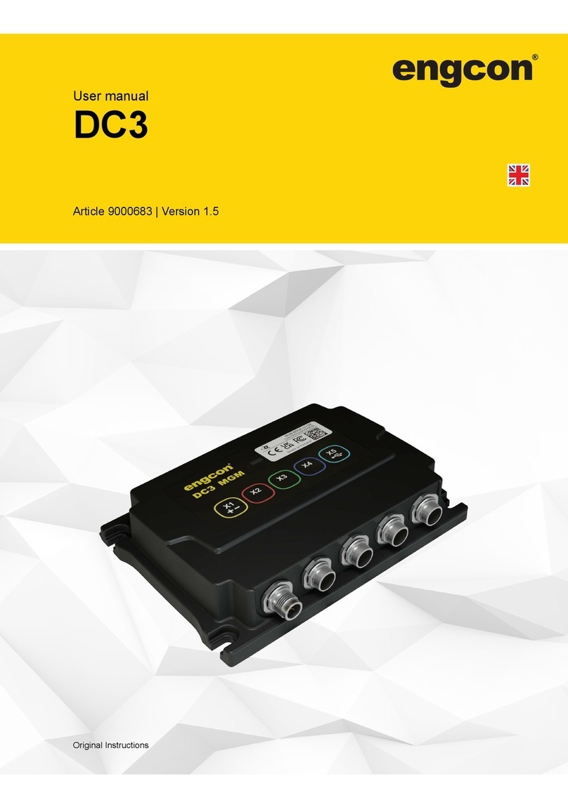
Engcon DC3 User manual

Installation instructions
DC3
Control systems
Article 9000695 | Version 1.2
Installation instructions in English

Preface
Preface
Dear Customer,
Thank you for choosing a product from engcon.
engcon is the market leader in tiltrotators and tools for excavators. We represent
innovation, knowledge and experience, and we develop our products with a focus on the
customer's needs. Please visit our website for contact information and details about the
rest of our product range.
www.engcon.com
2

Table of Contents
Table of Contents
1. Introduction
1.1. General............................................................................................................ 5
1.2. Scrapping and recycling.................................................................................. 5
1.3. Technical support and spare parts.................................................................. 5
1.4. Product approval............................................................................................. 6
1.4.1. Declaration of incorporation of partly completed machinery.................... 6
1.4.2. EU Declaration of Conformity.................................................................. 7
2. Safety
2.1. General............................................................................................................ 8
3. Installation
3.1. Responsibility...................................................................................................9
3.2. System overview DC3..................................................................................... 10
3.3. Hydraulics........................................................................................................ 11
3.3.1. Installing the ground pressure sensor..................................................... 11
3.4. Electronics....................................................................................................... 12
3.4.1. Electrical compound.................................................................................12
3.4.2. Cable marking..........................................................................................12
3.4.3. General Overview - Machine kit.............................................................. 13
3.4.4. Cable types..............................................................................................14
3.4.5. Overview – location of cabling in cab......................................................15
3.4.6. Install the electronics module (MGM)...................................................... 16
3.4.7. Installing the control panel (QPM)........................................................... 18
3.4.8. Install cabling (X1)................................................................................... 20
3.4.9. Install cabling (X2)................................................................................... 24
3.5. Constant flow...................................................................................................26
3.6. Decals..............................................................................................................27
3.6.1. Affix a decal in cabin............................................................................... 27
3.6.2. Update the base machine’s instructions for use...................................... 28
4. Starting the system
4.1. Read the DC3 instructions for use..................................................................29
4.2. eTT - engcon TechTool................................................................................... 29
4.2.1. Creating an account.................................................................................29
4.2.2. Download................................................................................................. 29
5. On completion
5.1. Document checks............................................................................................30
5.2. Documenting the installation........................................................................... 31
6. Decals
6.1. MGM................................................................................................................32
6.2. 9000672...........................................................................................................33
6.3. 9000678...........................................................................................................34
3

Table of Contents
7. Technical data
7.1. Electronics module - MGM..............................................................................35
7.1.1. Connector overview................................................................................. 35
8. Glossary
8.1. Abbreviations................................................................................................... 37
4

1 Introduction
1. Introduction
1.1. General
These installation instructions contain important information about how your product
is assembled and installed. Before you begin to assemble and use the product, it is
important that you read and understand the contents of the installation instructions,
especially the sections describing safety.
In addition to these installation instructions, you must read and understand the applicable
safety information for the relevant base machine as well as any other equipment.
Information, images, illustrations and specifications are based on the product information
available at the time of printing the installation instructions. Images and illustrations in the
installation instructions are typical examples and are not intended to be exact depictions of
different parts of the product. We reserve the right to make changes without prior notice.
Always make sure you have the latest version of the installation instructions. You can find
the latest version by logging in to www.engcon.com.
1.2. Scrapping and recycling
engcon makes constant efforts to reduce its environmental impact. engcon's products
comprise at least 99 per cent recyclable material. All assembly and service work must
take place in compliance with legislation and ordinances governing the environment,
health and occupational safety. This refers to all work with residual materials including
handling, storage and processing. To prevent contamination of soil and water, spillages
must be avoided. Should a spillage occur, it must be dealt with.
Hazardous waste may only be disposed of by those authorised to do so. All waste
produced must be disposed of in compliance with applicable legislation and ordinances:
- Metal and plastics to be recycled.
- Hydraulic hoses are normally used for energy recovery (sort as hazardous waste).
- Oils and greases are normally used for energy recovery (sort as hazardous waste).
- Electronic components to be recycled for materials (sort as hazardous waste).
- Packaging to be sorted at source and recycled for materials.
- Paper to be sorted at source and recycled for materials.
If in doubt, contact the environmental manager at engcon.
1.3. Technical support and spare parts
Contact information for support and spare parts can be found at www.engcon.com.
5

1 Introduction
1.4. Product approval
1.4.1. Declaration of incorporation of partly completed machinery
Product: engcon DC3 controlsystem
Manufacturer: engcon Nordic AB - Industricentragatan 4, 833 93 Strömsund, Sweden
THE OBJECTS DESCRIBED ABOVE IS IN CONFORMITY ITH
Applied and fulfilled essential requirements of 2006/42/EC.
Annex I - Essential Health and Safety Requirements
1.1.1
1.2.2
1.5.1
1.7.3
3.3.2
1.1.2
1.2.3
1.7.1
1.7.4
3.3.3
1.2.1
1.2.4.1
1.7.2
3.3.1
3.3.5
Technical documentation, 2006/42/EC: Compiled in accordance with part B of Annex VII.
Other relevant EU Directives: Radio Equipment Directive (RED) 2014/53/EU
(Further specified in separate EU Declaration of Conformity)
THIS DECLARATION OF INCORPORATION IS ISSUED UNDER THE SOLE RESPONSIBILITY OF THE
MANUFACTURER
Undertaking to transmit: The manufacturer will in response to a reasoned request by the national
authorities, transmit relevant information on the partly completed machinery. This shall be done without
delay via email and prejudice to any intellectual property rights of the manufacturer of the partly completed
machinery.
Terms: The partly completed machinery must not be put into service until the final machinery into which it is to
be incorporated has been declared in conformity with the provisions of Directive 2006/42/EC.
PERSON AUTHORISED TO COMPILE THE RELEVANT TECHNICAL DOCUMENTATION
Peter Huczkowsky – Product owner, Kanslihusgränd 2, 831 32 Östersund,Sweden
SIGNED FOR AND ON BEHALF OF
Krister Blomgren – Signatory, engcon Nordic AB
Strömsund, 2023-04-26
6

1 Introduction
1.4.2. EU Declaration of Conformity
Product: engcon DC3 controlsystem
Manufacturer: engcon Nordic AB - Industricentragatan 4, 833 93 Strömsund, Sweden
THE OBJECT DESCRIBED ABOVE IS IN CONFORMITY ITH
Relevant EU harmonisation legislation: Radio Equipment Directive (RED) 2014/53/EU
Harmonised standards (RED)
Article 3.1 a (Electrical safety):
EN ISO 60204-1:2018
Article 3.1 b (EMC):
EN ISO 13766-1:2018, EN ISO 13766-2:2018
Article 3.2 (Radio):
ETSI EN 300 328 v 2.2.2
THIS DECLARATION OF CONFORMITY IS ISSUED UNDER THE SOLE RESPONSIBILITY OF THE
MANUFACTURER
Object of the declaration: The object is a control system aimed to control equipment attached to an
excavator, as well as the excavator itself. The declaration concerns the control system fitted to the excavator
and not any interchangeable equipment that may be installed to the excavator, such as a engcon tiltrotator.
The object has radio connection features for setting and calibration purposes.
SIGNED FOR AND ON BEHALF OF
Krister Blomgren – Signatory, engcon Nordic AB
Strömsund, 2023-04-26
7

2 Safety
2. Safety
REMARKS
The stated safety information is independent of the base
machine and is directly concerned with the engcon DC2.
REMARKS
Other safety instructions can be found in the tiltrotator user
manual.
2.1. General
It is important that you read and understand all the warning texts before you begin
installing or using the product and any accessories supplied. The warning texts highlight
potential risks and how to avoid them. The following warning levels appear in these
installation instructions:
DANGER
Indicates that an accident will occur if the regulation is
not followed. Risk of personal injury or death.
WARNING
Indicates that an accident may occur if the regulation
is not followed. Risk of personal injury or death.
CAUTION
Indicates that an accident may occur if the regulation
is not followed. Risk of personal injury.
IMPORTANT
Indicates that an accident may occur if the regulation is
not followed. Risk of damage to property, process or the
surroundings.
REMARKS
Specifies additional information that may make performance or
understanding of specific operations easier.
8

3 Installation
3. Installation
It is important to check the necessary additional documentation before installation. At time
of delivery, your product and supplementary documentation are as far as possible adapted
to your base machine.
WARNING
If you have any doubts concerning the safety aspects
of your knowledge, the equipment or work, contact
a dealer or engcon Nordic AB. Incorrect installation
affect safety.
WARNING
Switch off power when working on the electrical
system and remove any live objects before starting
work Risk of personal injury.
IMPORTANT
Assembly and installation may only be carried out at a
workshop authorised by the manufacturer. Changes to the
assembly may not be carried out without the manufacturer’s
consent.
3.1. Responsibility
This installation kit is designed to be installed on machines specified by the kit and
installation instructions. The kit is designed to emulate a signal from a factory-installed
control device, control a valve connected in parallel or alternatively affect a valve already
installed on the machine.
In the event that the kit is a generic kit, the installer of the kit is responsible for ensuring
that the machine has maintained safety and that the machine kit when connected does not
change or otherwise affect the machine's procedure in the event of a fault.
The procedure for faults must be the same with the installation kit installed as for faults
on the original function or control unit. The procedure in the event of a fault is thus the
same, with or without the installation kit, and the installation kit thus has no additional
requirements for safety or hydraulic safety valve.
9

3 Installation
3.2. System overview DC3
EC
!
Position
Designation
1
Electronics module - MGM
2
Joystick- MIG2
3
Control panel - QPM
4
Ground pressure sensor
5
Electronics module - QLM
6
Connector - ILME
10

3 Installation
3.3. Hydraulics
3.3.1. Installing the ground pressure sensor
DANGER
Check that the boom is in contact with the ground
before installing the ground pressure sensor. Risk of
personal injury or death.
WARNING
The hydraulic system must be de-pressurised before
work on the system is begun. Risk of personal injury
and damage to property.
The ground pressure sensor measures the pressure in the boom cylinder and is used to
make sure the bucket has ground contact. Install the ground pressure sensor on the boom
cylinder block using the adapter kit supplied.
1
Position
Part number
Description
1
8001965
Ground pressure sensor
11

3 Installation
3.4. Electronics
WARNING
PWM signal emulation is not allowed on machines that
switch between auxiliary hydraulic control and wheel
control. Risk of injury or death.
3.4.1. Electrical compound
We recommend the application of electrical compound on all electrical contacts to prevent
corrosion. Remove any contamination before application.
Recommended compound:
We recommend the use of electrical compound without harmful or caustic properties;
intended for the prevention of corrosion.
3.4.2. Cable marking
It is useful to label cables with the stickers supplied to facilitate both installation and
troubleshooting.
Refer to the cable label sticker sheet on page 33.
12

3 Installation
3.4.3. General Overview - Machine kit
DC3 MGM
ECU
EC
!
C H H
C
C
O
H
H
F
D
DA
B
B
B
I
I
13

3 Installation
3.4.4. Cable types
Type
Description
A
Cable Bat -> DT-4S DC3
B
Cable DT-4P -> 2x DT-4S Y-splitter DC3
C
Cable DT-4P -> M12-5S DC3
D
Cable DT-4P -> DT-4S DC3
F
Cable DT-4P -> ILME DC3
H
Cable M12-5P -> M12-5S DC3
I
Cable M12-5P -> 2x M12-5S Y-splitter-DC2-DC3
O
Cable M12-5P -> M8-5S DC3
14

3 Installation
3.4.5. Overview – location of cabling in cab
QPM
MIG2
MIG2
MGM
ECU
15

3 Installation
3.4.6. Install the electronics module (MGM)
REMARKS
Remove the seat from the machine to make installation easier.
DC3 MGM
Install the electronics module in a suitable location using the installation kit supplied.
Part number
Description
8001500
Electronics module - MGM
8001987
Installation kit MGM
16

3 Installation
3.4.6.1. Assembly kit 8001987
1
3
7
5 64
2
Position
Part number
Description
1
1069556
Attachment plate
2
611817
Bolt K65 5x10H 10.9
3
611004
Washer BRB FZB 6.4x12x1.6
4
6000371
Bolt MF6S 5x16 10.9
5
611004
Washer BRB FZB 6.4x12x1.6
6
610920
Nut M6M M5 Lock
7
8001986
Magnet 32x7mm
17

3 Installation
3.4.7. Installing the control panel (QPM)
IMPORTANT
Installing the QSC panel (QPM) so that unintended operation of
the machine is avoided.
Install the QPM such that it is easily accessible to the operator using the installation kit
supplied.
18

3 Installation
3.4.7.1. Assembly kit 8000986
123
4
Position
Part number
Description
1
8000138
Electronics module QPM - QSC
2
1042165
Attachment plate to QPM; included in installation kit 8000986
3
1042177
Attachment fitting - tape attachment plate QPM; included in
installation kit 8000986
4
1027292
Thermoplastic bolt TPPT 25×10 fzb; included in installation kit
8000986
19

3 Installation
3.4.8. Install cabling (X1)
3.4.8.1. Cable routing and connectors (X1)
Position
Description
1
ILME connection
2
QLM connection
3
Connecting the ground pressure sensor
4
Power supply connection
5
MGM connection
20
Other manuals for DC3
2
This manual suits for next models
1
Table of contents
Other Engcon Control System manuals
Popular Control System manuals by other brands

LEGRAND
LEGRAND QMotion QzHub3 Guide

Roth
Roth Touchline SL Installation

Motorline professional
Motorline professional MPIE10 installer and user manual

CAME
CAME G5000 Installation, operation and maintenance manual

Honeywell
Honeywell Tradeline H1008D installation instructions

Proma
Proma MyPlasm CNC Installer manual

Evco
Evco Vcolor 318 M Installer manual

Topcon Positioning Group
Topcon Positioning Group NORAC UC5 installation manual

btsr
btsr WINDINGFEEDER operating manual

Crestron
Crestron CP2 Operation guide

NPI
NPI INR-01-T Operating instructions and system description

Tecnoalarm
Tecnoalarm TP8-64 BUS Installer manual