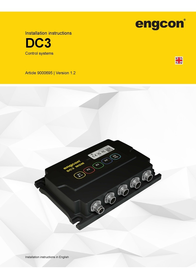
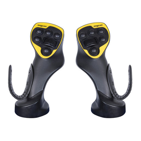
Engcon DC2 User manual

User manual
Constant flow
Article | 9000225
Language
Country
Original Instructions

Preface
Preface
Dear Customer,
Thank you for choosing a product from engcon.
engcon is the market leader in tiltrotators and tools for excavators. We represent
innovation, knowledge and experience, and we develop our products with a focus on the
customer's needs. Please visit our website for contact information and details about the
rest of our product range.
www.engcon.com
2

Table of Contents
Table of Contents
1. Introduction
1.1. General............................................................................................................ 4
1.2. Scrapping and recycling.................................................................................. 4
1.3. Technical support and spare parts.................................................................. 4
1.4. Product approval............................................................................................. 5
1.4.1. Declaration of Incorporation.....................................................................5
2. Safety
2.1. General............................................................................................................ 6
3. Operation
3.1. Programming sequence.................................................................................. 9
3.2. Activation sequence........................................................................................ 10
3.3. Deactivation of constant flow.......................................................................... 11
4. Troubleshooting
3

1 Introduction
1. Introduction
1.1. General
This user manual contain important information about your product's functions and
characteristics, and how to use it in the best way. Before you begin using the product, it is
important that you read and understand the content of these instructions, especially the
sections that address safety.
In addition to these instructions, you must study and understand the applicable safety
information for the relevant base machine as well as any other equipment involved.
The user manual is supplied with supplementary documentation providing more detailed
descriptions of the installation, fitting, operation and maintenance of control systems and
custom modifications for your specific product.
Information, images, illustrations and specifications used in the instructions are based
on product information that was available at the time of going to press. Images and
illustrations used in the instructions are typical examples and not intended to be exact
depictions of various part of the product. We reserve the right to make changes without
prior notice.
Always store the user manual together with any other supplementary information in a safe
manner and such that it is always available.
1.2. Scrapping and recycling
engcon makes constant efforts to reduce its environmental impact. engcon's products
comprise at least 99 per cent recyclable material. All assembly and service work must
take place in compliance with legislation and ordinances governing the environment,
health and occupational safety. This refers to all work with residual materials including
handling, storage and processing. To prevent contamination of soil and water, spillages
must be avoided. Should a spillage occur, it must be dealt with.
Hazardous waste may only be disposed of by those authorized to do so. All waste
produced must be disposed of in compliance with applicable legislation and ordinances:
- Metal and plastics to be recycled.
- Hydraulic hoses are normally used for energy recovery (sort as hazardous waste).
- Oils and greases are normally used for energy recovery (sort as hazardous waste).
- Electronic components to be recycled for materials (sort as hazardous waste).
- Packaging to be sorted at source and recycled for materials.
- Paper to be sorted at source and recycled for materials.
If in doubt, contact the environmental manager at engcon.
1.3. Technical support and spare parts
Contact information for support and spare parts can be found at www.engcon.com.
4

1 Introduction
1.4. Product approval
1.4.1. Declaration of Incorporation
The declaration refers to the engcon DC2 control system.
Upon reasoned request by a national authority, engcon will undertake to provide relevant information about the
machine.
The control system may not be put into operation before the machine it will be built into is in conformance with
Directive 2006/42/EG.
engcon hereby declares that the control system conforms to the below-mentioned basic safety requirements
as described in appendix 1, items1 and 3, in Directive 2006/42/EG, and that the relevant documentation as
described in appendix 7, section B has been compiled.
We hereby declare that the control system conforms with 2014/30/EC and 2006/42/EC.
Harmonized standards
Designation
SS-EN ISO 13849-1:2008
Safety of machinery – Safety-related parts of control systems –
Part 1: General principles for design
SS-EN ISO 12100:2010
Safety of machinery – General principles for design – Risk
assessment and risk reduction
SS-EN 474-1:2006+A3:2018
Earth-moving machinery – Safety – Part 1: General
requirements
SS-EN 474-5:2006+A4:2013
Earth-moving machinery – Safety – Part 5: Requirements for
hydraulic excavators
SS-EN 60204-1:2006
Safety of machinery – Electrical equipment of machines – Part
1: General requirements
SS-ISO 15998:2008
Earth-moving machinery – Machine-control systems (MCS)
using electronic components – Performance criteria and tests
for functional safety
SS-EN 13309:2010
Construction machinery – Electromagnetic compatibility of
machines with internal power supply
Stig Engström, CEO
Qualified person authorized to compile the technical documentation:
Peter Huczkowsky, CIO & Head of Control Systems
engcon Control Systems
5

2 Safety
2. Safety
REMARKS
The stated safety information is independent of the base
machine and directly concerns the engcon DC2.
REMARKS
Other safety instructions can be found in the tiltrotator user
manual.
2.1. General
It is important that you read and understand all warnings prior to installation work on this
product or before you use it and any accessories supplied. The warning texts highlight
potential risks and describe how to avoid them. The following warning levels are used in
this user manual:
DANGER
Indicates that an accident will occur if the regulation is
not followed. Risk of personal injury or death.
WARNING
Indicates that an accident may occur if the regulation
is not followed. Risk of personal injury or death.
CAUTION
Indicates that an accident may occur if the regulation
is not followed. Risk of personal injury.
IMPORTANT
Indicates that an accident may occur if the regulation is
not followed. Risk of damage to property, process or the
surroundings.
REMARKS
Specifies additional information that may make performance or
understanding of specific operations easier.
6

3 Operation
3. Operation
Make sure you have read and understood the entire chapter entitled Operation before
beginning the programming sequence.
The constant flow function in DC2 enables certain selected functions to run without
actively operating DC2 controls. When the constant flow function is installed according
to 9000224 Installation Instructions, selected functions can be activated to run without
operating the controls; all that is required is activation of constant flow. Activation/
deactivation of constant flow can be summarized as follows:
1. Programming sequence – specific functions and the specific flows they will have when
constant flow is activated are determined in the programming sequence.
2. Activation sequence – the activation sequence starts constant flow to selected
functions.
3. Deactivation – when constant flow is deactivated, all active functions that were started
in the activation sequence are stopped.
WARNING
If you have any doubts concerning the safety aspects
of your knowledge, the equipment or work, contact
a dealer or engcon Nordic AB. Incorrect installation
affect safety.
WARNING
Beware of moving parts. A lack of awareness may lead
to crush injuries. Risk of personal injury.
WARNING
Never attempt to increase the maximum capacity
of the equipment by modifications not approved by
the supplier. Risk of personal injury and damage to
property.
CAUTION
If constant flow is activated without activating a
function, the tiltrotator or tool may start unexpectedly
without any controls having been moved.
7

3 Operation
IMPORTANT
Maintenance and repair of the electrical system may only be
carried out by professionally qualified persons.
8

3 Operation
3.1. Programming sequence
1. Operate the desired function(s) using rollers or buttons: Extra1, Extra2, PWM5 or
PWM6. (Refer to the decal in engcon's user manual.) Example illustrated below when a
function is programmed to a roller and button:
EXTRA 2
2146492
2. Press the constant flow button; after 3 seconds a buzzer will sound in the DC2 cabin
module. Release the function roller/button:
- Speed and direction are locked for the constant flow functions in operation.
- The constant flow functions' speed and direction are saved.
WARNING
Beware of moving parts. A lack of awareness may lead
to crush injuries. Risk of personal injury.
9

3 Operation
3.2. Activation sequence
Can be operated immediately after the programming sequence without releasing the
button.
1. Hold down the constant flow button; selected functions are activated with the
programmed speed and direction.
2147270
2. After 3 seconds a buzzer will sound in the DC2 cabin module. If the operator releases
the button within 2 seconds after the audible signal (buzzer in the DC2 cabin module will
sound during these 2 seconds):
- The constant flow functions are activated.
- The audible signal is activated.
10

3 Operation
Check that constant flow is functioning (e.g. that the rotating brush is rotating).
Check that the indicator lamp is on.
1
8
1
916
2
2155148
Position
Description
1
Constant flow indicator lamp in the joystick button with LED. Same as the button
selected for constant flow activation.
2
Indicator lamp that lights up when constant flow is activated installed in a conspicuous
place in the cab
IMPORTANT
If the button is not released within 2 seconds, the constant flow
function will start and the activation sequence must then be
restarted.
WARNING
Beware of moving parts. A lack of awareness may lead
to crush injuries. Risk of personal injury.
CAUTION
If constant flow is activated without activating a
function, the tiltrotator or tool may start unexpectedly
without any controls having been moved.
3.3. Deactivation of constant flow
Constant flow is deactivated for all activated functions should any of the below occur:
- Any of the constant flow functions is activated manually by a button or roller (e.g. if
Extra1 on the roller is moved, constant flow is deactivated).
11

3 Operation
- The constant flow button is depressed.
- The safety gate is opened.
- Faulty constant flow button.
12

4 Troubleshooting
4. Troubleshooting
Description of fault
Possible cause(s)
Suggested action
The alarm ”CONST FLOW
BLOCKED BY SAFETY GATE”
will be shown in the cabin module
display and in Microconf when a
constant flow button is depressed.
1. Safety lock lever signal not
connected.
2. Safety lock lever signal
incorrectly connected/
incorrectly configured.
3. Safety gate open.
4. Safety gate closed at system
start.
1. Check that the safety lock
lever signal is installed.
2. Check that the safety lock
lever signal is correctly
connected and correctly
configured.
3. Close the safety gate.
4. Open and close the safety
gate.
After a 2-second audible signal
from the DC2 cabin module,
the selected function will stop
working.
Activation interval exceeded.
During the activation system,
the constant flow button must be
released within 2 seconds.
Nothing happens when a constant
flow button is held down for 3
seconds or more.
Constant flow incorrectly
configured.
Check the constant flow installation
and configuration according to
9000224 Installation Instructions.
When the program sequence
is complete and the activation
sequence is performed, nothing
happens on the programmed
function.
The programmed function is not
activated for constant flow.
Check that the constant flow
configuration on the selected
function is activated for constant
flow activation.
The alarm ”CONST FLOW
BLOCKED BY PARAMETER
ERROR” will be shown in the
cabin module display and in
Microconf.
Incorrect parameter entry in the
cabin module.
Contact support.
13

Notes
........................................................................................................................................
........................................................................................................................................
........................................................................................................................................
........................................................................................................................................
........................................................................................................................................
........................................................................................................................................
........................................................................................................................................
........................................................................................................................................
........................................................................................................................................
........................................................................................................................................
........................................................................................................................................
........................................................................................................................................
........................................................................................................................................
........................................................................................................................................
........................................................................................................................................
........................................................................................................................................
........................................................................................................................................
........................................................................................................................................
........................................................................................................................................
........................................................................................................................................
........................................................................................................................................
........................................................................................................................................
........................................................................................................................................

Version | 1.3
engcon North America Inc.
2666 State St. 9, Hamden, CT 06517
Phone +1 (203) 691 5920,
www.engcon.com
Other manuals for DC2
2
This manual suits for next models
1
Table of contents
Other Engcon Control System manuals