Engine Clean Solutions OIL RX-3000 User manual

OIL RX•3000
Dynamic Cleaning
Oil Lubrication Systems
Reference Manual

OIL SYSTEM SERVICE
TOPIC PAGE
SAFETY INFORMATION……………………………………………………3
INTRODUCTION……………………………………………………………..4
FIRST TIME OPERATION…………………………………………………..5
FEATURES AND CONTROLS................................................................6
CLEANING THE OILING SYSTEM……………………………………..….9
TROUBLESHOOTING GUIDE………………..........................…….......12
SYSTEM MAINTENANCE………………………………………………....14
OIL FILTER ADAPTER & PARTS….......................................................15
WARRANTY AND OWNER REGISTRATION….........................……....17
Page 2

SAFETY INFORMATION
This equipment is to be operated by qualied personnel. It should only be oper-
ated after reading the instruction manual and understanding the safety informa-
tion contained therein.
• Wear safety glasses when operating
• Do not smoke near the machine
• Do not inhale or breathe the fumes from the machine or the exhaust fumes
from the engine.
• Use in a well ventilated area
• Read and understand the material safety data sheet
• Immediately repair any leaks in the machine or adapters
• Immediately clean up any spills Keep a re extinguisher handy
• Keep the lines (hoses) from moving parts & hot objects
• Do not exceed the pressure for which the machine was set. To do so
could cause engine damage, possible personnel injury and void the war-
ranty.
• Do not use any cleaning solvent in this machine unless it is recommended
by the manufacturer
Page 3

INTRODUCTION
Simple and easy to operate, the OIL RX-3000, when used with authorized cleaning
solutions, removes carbon, sludge, varnish, gum, and other contaminants from the
engine’s oiling systems and related surfaces. This is accomplished by a connect
the machine’s oil inlet and return lines to the engine’s oil lter port.
The machine is powered by compressed air and the vehicle’s oil pump.
The engine’s oil is not required to be drained until after the cleaning process has
been completed.
While the engine is run at idle, a mixture of cleaning solution and motor oil is cir-
culated through the engine’s entire lubricating system, including the engine valve
covers, valve train and crankcase side walls and all oil-wetted surfaces. Sludge
and contaminants are removed from the engine by the machine’s 5-micron lter.
This lter is replaced after each service is performed.
An air ush feature is used to remove any leftover motor oil and cleaning solution
via the oil pan’s drain plug opening. The OIL RX-3000 series machines can also
measure the engine’s oil pump ow and oil pump pressure via a ow meter and a
pressure gauge. The OIL 3000 has a 64 ounce (1 LITER) reservoir for cleaning
solution.
NOTE: The machines new uid tube is used as a gauge to meter the precise
amount of cleaning solution into the oiling system’s oil stream.
When the timer has gone to zero the service is nished.
Two (2) lter bowls are available:
A 5” bowl for cleaning gasoline engines and a 10” bowl for cleaning diesel en-
gines.
The gas and diesel cleaning solution and lter kits are sold separately.
Page 4

FIRST TIME OPERATION
REFER TO FIGURES A, B, C, D, AND E
Read the safety instructions and this entire manual
1. Pour 32 or 64 ounces of cleaning solution in the oil solution reservoir (B)
through the ll spout
2. The Oil RX - 3000 operate s on a minimum of 50 psi of compressed air.
Connect air line to the port marked “air inlet” (2). Note the reading on the
air pressure gauge attached to the air pressure regulator. It should read
no more than 35 psi. If an adjustment is needed, pull down on the black
knob and adjust accordingly. Push up on the adjusting knob to re-lock the
regulator in position.
3. Make sure the pet cock located on the oil lter bowl is closed.
4. The Oil 3000 machine is now ready for service.
Page 5

MODEL OIL RX - 3000
FIGURE 3000
K - FILTER BOWL
B - NEW FLUID
FILL
C - FLOW METER
A - PRESSURE
RELIEF VALVE
E - TIMER
D - PRESSURE
GAUGE
I - INLET (RED)
J - RETURN (BLACK)
L - DRAIN COCK
G - AIR FLUSH
F - ADD SOLUTION
SWITCH
H - VACUUM RELEASE
PAGE 6
M - SHOP AIR
CONNECT

SYSTEM FEATURES
(A) Pressure Relief Valve - Add solution.
(B) New Fluid Fill - add up to 64 ounces (about 1 liter) cleaning solution
(C) Oil Flow Meter shows how much oil the engine’s oil pump Is delivering
back to the Oil 3000 ltering system.
(D) Oil Pressure Gauge shows how much oil pressure the engine’s oil pump
Is producing at idle.
(E) Timer, when elapses to zero, “O”, sounds a buzzer.
(F) Oil Solution Pump – Toggle switch transfers the EFX-601 cleaning solu-
tion to the oil lter bowl.
(G) Air Flush-Switch allows air into the engine’s oil galleys to remove any
residual oil/solution from the engine.
(H) Vacuum Breaker at the top of the lter bowl housing is pressed when the
lter bowl is to be removed.
(I-J) Inlet & Return Lines are color coded - red for inlet and black for return.
(K) Filter Bowl - with 5-micron sediment lter.
(L) Drain Cock - Open to drain uid prior to removing lter.
(M) Shop Air Connect - Connect to shop air
PAGE 7

CLEANING THE OIL SYSTEM
Overview
When cleaning the oiling system set engine speed at idle, or slightly above idle.
This is the most efcient and thorough method for cleaning the complete inside
of the engine’s oiling system including the hydraulic lifters, valve train, gear train,
oil pump, valve cover, crankcase sidewalls, oil galleys, and oil pan and any other
“oil-wetted” surfaces located inside the engine. Engines that are burning oil or
have other symptoms of low compression or poor mechanical condition should
not be cleaned.
• The machine’s lter must be replaced at each cleaning.
• The engine’s oil lter must be replaced at each cleaning.
• The engine’s oil must be changed after each cleaning.
The engine must be warm when starting the procedure. Since the engine is run-
ning during the procedure, an auxiliary heater is not required. The engine will
provide its own heat to insure a more thorough cleaning.
The cleaning cycle must be at least 10 minutes. The normal cleaning time is be-
tween 10 and 20 minutes, although some engines, including diesel, may require
longer times to completely clean the oil system.
During the cleaning process, cleaning solution mixes with the engine’s oil, as the
oil passes thru the oil lter mounted on the Oil 3000. The engine’s oil provides
lubrication for the engine and is the carrier for the cleaning compounds located in
the cleaning solution.
The cleaning solution/oil will circulate thru the machine, and the machine’s lter,
about 4 or 5 times per minute (average gasoline engine). The cleanig solution
will dissolve the sludge, varnish and tar inside the engine using the churning ac-
tion of the internal moving engine parts. The heavier contaminants, such as wear
metals and gasket particles, are ushed into the oil pan where they are picked
up by the engine’s oil pump and ltered out by the 5-micron lter located on the
machine.
At the end of the cleaning cycle, the oil is drained, and the engine is air ushed to
remove excess cleaning solution/oil that may be in the oil galleys, etc. Leaving a
small amount of cleaning solution in the engine is benecial, as it contains a seal
rejuvenating and oil conditioner.
Dispose of the old drain oil as you would regular drain oil.
PAGE 9

CLEANING THE OIL SYSTEM
Step 1: Make sure the oil level in the engine is at least at the low mark. Make sure that
the engine is warm. Pour EFX cleaning solution into the machine’s tube reservoir.
Empty the lter bowl and install a new lter. Make sure the pet cock is closed.
Step 2: Remove the oil lter from the engine and replace it with the correct oil lter
adapter, using appendix ”b” as a guide.
Note: the adapters will spin-on-easily – do not force
them. Hand tight only.
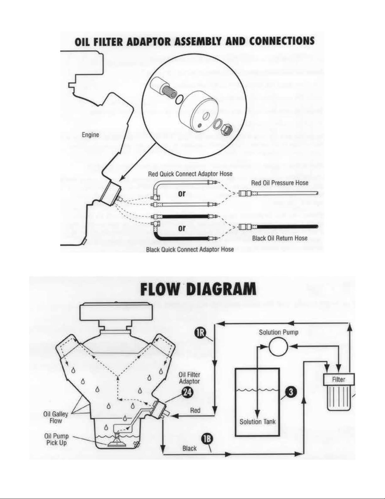
Attach the red oil line (1r) to the center port on the oil lter adapter and the
black line (1b) to the side port.
Note: the center port is threaded 12mm for the red adapter lead (24a) and the
side port is threaded 10mm for the black adapter lead (24b).
Make sure all the control buttons are in the off position; that is, they are in the
“down” position. Attach an air line to the port marked “air inlet” located on the
side or back of the machine.
Step 3: Flip up the red switch (4) until the desired quantity of cleaning solution is
injected into the oil lter port. Start the engine and let it idle. Observe that
there is oil ow thru the ow meter (5) and that the oil pressure gauge (7)
shows pressure. Set the timer from between 10 and 20 minutes and
turn on the buzzer switch (9). check for leaks.
Step 4: When the timer goes back to zero, turn off the buzzer and shut off the engine.
Drain out the old oil and cleaning solution. While the drain plug is out,
ip the (6) air ush switch. This will ush out any excess oil/solution from the
engine. About 30 seconds is sufcient. Install the drain plug, remove the oil
lter adapter, install a new oil lter and ll the crankcase with motor oil. Start
the engine, check for leaks and recheck the oil level.
PAGE 10

CLEANING THE OIL SYSTEM
Drain the oil lter bowl by opening the pet cock and pressing the vacuum breaker
button (10) located on the top of the oil lter bracket. Once the oil level has
dropped enough to remove the bowl without spilling oil, remove it and drain it.
Install a new 5-micron lter element and replace the bowl. Use the wrench pro-
vided to tighten the lter bowl.
Shop Notes: the oil ow meter oat should be at the top of the meter anytime
the engine is running. If it is not, it could be an indication of a plugged oil pump
pick-up screen, a weak oil pump or a plugged lter on the machine. To determine
which problem is present, slightly increase the idle speed. If the ow meter goes
to the top, then the oil pump is weak (at Least at idle speed). If the ow meter
does not go to the top at increased idle speed, turn off the engine and replace
the 5-micron lter. If the problem persists, then the oil pump pick-up screen is
plugged.
If there is no ow, stop the Engine and repair the problem. If there is some ow,
the cleaning process will probably clean the screen, unless there is a substantial
amount of gasket material or silicone sealer in the oil pan.
Do not rely on the oil pressure gauge by itself to determine the condition of the oil
pump and the pick-up screen. The oil ow meter is a more reliable indicator.
Warning: use only genuine engine clean lters. Other lters will not t and can
result in engine damage. Under no Circumstances can you use a “string wound”
lter in this machine.
Reorder lters by using these numbers:
Gasoline engines – no. 50022 (5” 5-Micron gradient rated)
Diesel engines – no. 50023 (10” 5-Micron gradient rated)
PAGE 11

Solution pump does not function:
1. Low inlet air pressure - machine requires at least 50 psi to operate.
2. If no air pressure - check air line connection.
3. Check air pressure on gauge located inside machine. Psi should read 30 to 35 psi. If
low pressure, adjust the gauge accordingly.
4. If air pressure check is OK, then check air inlet to machines air pump by removing air
line going into pump. Turn on solution pump switch and check for air ow. If ow is
OK, replace pump.
No oil pressure and no oil ow:
1. Kinked return or pressure hose.
2. Check oil level in engine. Engine oil level must be to the low level mark on the dipstick.
3. Check for oil coming from inside machine at the hole in the bottom of the machine
housing.
4. Wrong adapter being used. Check for proper adapter in adapter application guide
Low oil pressure and low oil ow:
1. Partially kinked return and/or pressure hose.
2. Dirty lter - change machines lter before each cleaning.
3. Dirty screen in the machine lter head. Remove vent valve and blow air thru the screen
with the lter and bowl removed from the machine.
4. Weak engine oil pump - increase engine rpm and observe if the ow and pressure
increase. If ow and pressure increase the engines oil pump is weak at idle. If ow
pressure does not increase go to step 5.
5. Partially plugged engine oil pump pickup screen - let screen hot soak in the cleaning
solution for 15 minutes with the engine off. Then retry.
6. Engine oil is very thick and engine is cold. Disconnect machine and run engine until the
engine block is warm to the touch. Re-connect the machine and retry.
PAGE 12
TROUBLE SHOOTING GUIDE

SYSTEM MAINTENANCE
The Oil-3000 is designed to give many years of trouble-free operation and there
is virtually no maintenance required.
Periodically check for loose ttings and chafed lines and hoses. Replace any
damaged hoses or components.
Replace the oil lter O-ring, when needed. Avoid using pliers on the lter bowl.
Use the wrench provided.
Do not overtighten the oil lter adapters and leads. They are designed to be
hand tightened only.
The air pressure regulator, located on the side of the cabinet, is to be set at 30 to
35 psi. Periodically check the air pressure gauge, mounted on the air pressure
regulator, to insure the air pressure is 30 – 35 psi. (Adjust the air pressure regu-
lator by pulling out the adjusting knob to adjust the air pressure). Do not exceed
the 30-35 psi which is the factory recommended setting.
PAGE 13

LIMITED WARRANTY
This product is warranted by ENGINE CLEAN SOLUTIONS, INC. to be free
of defects in workmanship and materials for a period of one year from date of
purchase by original purchaser. If the product fails within this period, it will be
repaired or replaced at seller’s option; provided (1) the product is submitted with
proof of purchase date and (2) transportation charges are prepaid to the nearest
Service Center. Liability under this warranty is expressly limited to repairing or
replacing the product or parts thereof. This warranty does not apply to product or
parts broken by accident, negligence, overload, abuse, or if they have been tam-
pered with in any way. This warranty does not apply to service hoses and adapt-
ers that may need replacing do to normal wear. If this warranty does not apply,
then the purchaser shall pay all costs for labor, material and transportation. Note:
The use of this apparatus for any purpose other than the services described will
render this warranty null and void. No other warranties are expressed or implied.
PAGE 14
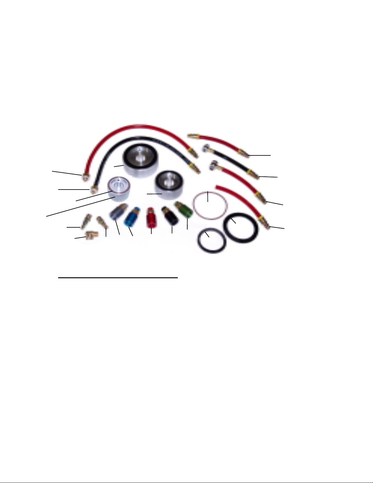
STANDARD ADAPTER PARTS
12
11
10 9
8
14
15
# Part No. Description
1 52310 3.5” / 4.0” Adapter Housing W/52311 Seal Ring
2 52300 3” Adapter Housing W/52301 Seal Ring
3 52320 22-1.5mm Threaded Adapter, Silver, W/Nut & Seal Rings
4 52330 20-1.5mm Threaded Adapter, Blue, W/Nut & Seal Rings
5 52340 18-1.5mm Threaded Adapter, Red, W/Nut & Seal Rings
6 52350 3/4-16” Threaded Adapter, Black, W/Nut & Seal Rings
7 52360 13/16-16” Threaded Adapter, Green, W/Nut & Seal Rings
8 52221 Adapter Lead, Red, 12mm Banjo, W/Large Plug End, 6”
9 52231 Adapter Lead, Black, 10mm Banjo, W/Large Plug End, 6”
10 52276 Adapter Lead, Red, 12mm Straight, W/Large Plug E RXnd, 18”
11 52286 Adapter Lead, Black, 10mm Straight, W/Large Plug End, 18”
12 80761 Open End Adapter w/3/8” Plug End
13 80941 Double End Connector W/3/8” Plug End
14 81370 1/4 male air chuck
15 20430 1/4 X 1/4 90-degree street elbow
16 20350 1/4 male air chuck
17 50301 O-Ring for lter housing (viton)
18 52301 Seal Ring for 3” Adapter (52300)
19 52311 Seal Ring for 3.5”-4” Adapter (52310)
20 52305 2.5” Adapter Housing W/52374 Seal Ring
21 52374 Seal Ring For 2.5” Adapter Housing (52305)
2
20
34567
17
18
19
13
1
16
21
PAGE 15
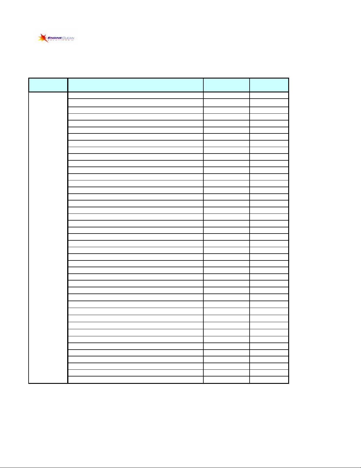
OIL FLUSH MACHINE ADAPTERS
CANISTER TYPE ADAPTERS (CLM)
PRICE LIST - 09/01/17
MFG P/N
ACURA LEGEND & SPORT COUPE (1986 & 87) 52400
AUDI AUDI-- 3.2L TT 52464
AUDI--S4, 8A, All TERRAIN 52467
BMW BMW--IL6, 2.5 & 2.8L. IL4, 2.8L 52410
BMW--L6 3.0, 3.2 & 3.5L -Two Adapters 52411
BMW--IL4 1.8 & 1.9L 52412
BMW--V8 3.0 & 4.0L. V12 5.0 & 5.6L 52413
BMW--V8 4.0 & 4.4L. V12, 5.4L 52414
BMW--3L DOHC 16 (330I) 52461
CITROEN CITROEN 52512
FORD FORD 6.0 DIESEL 52460
GM CADILLAC / SATURN 3.0L V6 52403
CHEVROLET/BUICK/OLDS 2.5L - FILTER IN PAN 52406
CADILLAC CTS 3.2 L 52510
HYUNDAI HYUNDI 3.3 L 52570
OLDS 3.5 V6 INTRIGUE 52418
LEXUS LEXUS-IS 250/350 52458
LEXUS- GS 300 52459
MBZ MBZ--IL4, 2.2 & 2.3L. IL6, 2.8, 3.0, 3.2 & 3.6L 52380
MBZ--V6, 2.8 & 3.2L. V8, 4.3 & 5.5L 52383
MBZ--V8, 4.2L, 5.6L 52386
MBZ--V8, 5.0L, 8.2L & E-Class 4.3L 52390
MBZ DIESEL--L4, L5, L6 52384
MBZ DIESEL--L4 & L5 52412
MBZ DIESEL--V6 52417
MAZDA MAZDA 6 52466
MINI MINI-COOPER/COOPER S 52465
PORSCHE PORSCHE--H6 3.2 & 3.6L 52388
LAND ROVER RANGE ROVER--V8-4.4L 52474
SATURN SATURN--L SERIES, V6-3.0L (2000 UP) 52403
SATURN--L4 2.2L 52449
TOYOTA AVALON 52468
TOYOTA 4 CYL 52475
TOYOTA 4-6 CYL 52476
TOYOTA 8 CYL 52477
TOYOTA 6 CYL INTL 52478
VOLVO VOLVO--ALL WITH FILTER IN OIL PAN 52389
VOLVO--2004 LATER 52462
VW VW--DIESEL, L4 1.9L GAS L4 1.8L 52379
VW--V6 2.8L (2000 & Older) 52402
VW-- 3.6L PASSAT (06/07) 52463
VW--2.5BTLE/JETA2.0LGOLF/GTI-R-32/JETA/PAS 52464
VW--V8 4.2 L 6.0L PHAETON 52467
PRICES ARE FOB BALDWIN PARK, CA
APPLICATION
Table of contents


