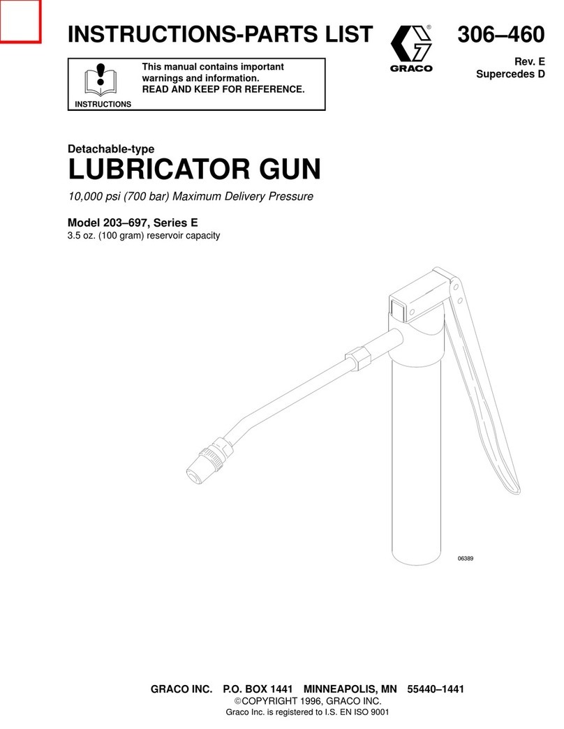
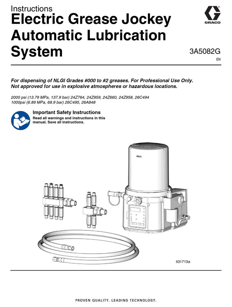
Graco Progressive Series User manual

COMPONENT INSTALLATION•
TUBING AND PIPE CLEANING•
SYSTEM LUBRICANT PREFILLING•
Series Progressive Lubrication

Series Progressive Lubrication Systems Installation Guide L40000
Page 2
INTRODUCTION
When installing a Series-Progressive lubrication system,
the installer must have a copy of the lubrication schematic
diagram that was developed when the system was designed.
The schematic diagram illustrates the approximate layout
of the components, their relationship to each other, and is
the authoritative and guiding document to be followed and
referred to during the installation process. It should include
specifications for the lengths and diameters of the tubing,
pipes, and hoses that were calculated into the overall system
design, as well as the types and styles of the fittings to be
used for the hydraulic connections. This Installation Guide
segment addresses lubrication system installations in general
terms with recommendations specific to Series-Progressive
centralized lubrication systems where applicable.
Depending upon the individual application requirements,
some system components are assembled at the factory prior
to shipment while others require assembly at the installation
site during the installation process. For instance, a series-
progressive system divider valve may be shipped fully
assembled and ready for assembly whereas some peripheral
accessories, such as limit switches, performance indicators,
proximity switches, etc., may be packed separately to reduce
risk of damage during shipment. Refer to the lubrication
schematic to determine the location of each component and
accessory. For those components and accessories that are
shipped un-assembled, refer to the literature that accompanies
each of them for specific instructions regarding their assembly
and installation.
System installation procedures for specific components utilized
in a series-progressive lubrication system are detailed in the
following paragraphs in this Installation Guide:
General Installation Guidelines•
Mounting the Pump•
Mounting Divider Valves•
Installing Check Valves•
Installing Tubing, Pipes, and Hoses•
Cleaning Tubing and Pipes•
Lubricant Filtration Requirements•
Prefilling the System with Lubricant•
Whenever possible, these guidelines and recommendations
should be followed during installation of the Series-Progressive
lubrication system by the machine manufacturer or any other
installer. This will enable the final customer or user to con-
veniently monitor and maintain the system integrity and
trouble-free operation efficiently and economically.

Series Progressive Lubrication Systems Installation Guide L40000
Page 3
a check valve and plug, should be installed at the highest
point of the header line, i.e., at the end point furthest from
the pump. See Figure 1.
If lubrication points are located on a portion of the6.
equipment that is moving, the divider valves should be
located to minimize the number of connecting hoses that
are required to be moving and flexing. See Figure 2.
Keep the lengths of installed tubing, pipes, and hoses7.
as short as possible in order to minimize the total line
volume/capacitance. Large line volumes increase the
time necessary to build up to system operating pressure
when the pump is activated, resulting in a slower system
response time. The system response time delay may
cause lube system fault indications when the allotted time
to achieve lubrication of all lube points (Monitor Time) is
exceeded. Therefore, designing and installing the system
overall configuration to minimize the total line lengths
and size is very important in optimizing the system
performance capabilities and minimizing response time.
See Figures 1 and 2 for examples and diagrams of these
general system configuration guidelines.
Installation Guide
GENERAL INSTALLATION GUIDELINES
The positioning and orientation of components relative to each
other is essential to ensure the correct function and operation
of any centralized lubrication system. Even if the proper
components have been selected, improper positioning may
make it more difficult to purge air out of the total system when
air-bleeding procedures are performed. Any trapped air left in
the lines or components of the lubrication system will impede
and degrade performance and response time capabilities.
The basic rules to be followed for proper component placement
are:
Place the pump at the lowest point in the system.1.
In smaller systems with only one or two lubrication zones,2.
position the master divider valve at the same level as the
pump, or slightly higher.
Place the master divider valve as close to the pump or3.
header line as possible.
Place the secondary divider valves above the master4.
divider valve(s), but below the majority of lubrication
points. Ideally, all of the secondary divider valves should
be located above all of the master divider valve(s), but
below all of the lubrication points.
In larger systems with multiple lubrication zones, a header5.
line may be used. In this case, the header should be
configured to rise up-ward from the pump connection
with a continuous positive slope. Also, a convenient means
of purging air out of the line, such as a T-connector with
Figure 1 Figure 2

Series Progressive Lubrication Systems Installation Guide L40000
Page 4
MOUNTING DIVIDER VALVES
The following recommendations apply when locating and
mounting divider valve blocks and should be adhered to as
closely as possible to assure that the lubrication system will
operate efficiently and accurately:
The divider valve assembly should be oriented so that the•
lube inlet port is at the top 12:00 o’clock position in order
to make the purging/ bleeding procedures easier and
more efficient.
The divider valve assembly should be oriented so that the•
spools in the working-valve sections operate parallel to
the floor. Avoid mounting the divider valves in such a way
that they are tilted relative to the floor plane or perpen-
dicular to it (see Figure 4).
Figure 3
MOUNTING THE PUMP
All pump and reservoir package combinations incorporate a
method for attaching them to a suitable mounting surface.
The pump should be located such as to make it the lowest
component in the lubrication system. Considerations for
placement of the pump include:
Mount the pump/reservoir package in a location that•
allows the reservoir to be easily accessible for observation
of its lubricant level and for easy refilling.
Locate the pump and reservoir in an area that is not•
subjected to heavy traffic and/or heavy debris or by-
products from the machine it is located on (see Figure 3).
Figure 4

Series Progressive Lubrication Systems Installation Guide L40000
Page 5
MOUNTING DIVIDER VALVES (continued)
Avoid locating the divider valve assembly in locations that•
restrict access to it. The ports on the front of the divider
valves should be accessible for prefilling and purging
procedures (see Figure 5).
The inlet and end sections of each divider valve have two
holes each to enable the installer to attach it to an appropriate
surface with properly-sized bolts. The valves may be attached
directly to one of the machine surfaces if the surface can be
drilled and tapped, but the mounting surface should be flat in
order to prevent the divider valve from being deformed. Other
mounting variations may require the use of a mounting plate
interface. Graco has several styles of mounting plates available
for straightforward installations. Also, a customized design
can be developed for those installations that require special
considerations and hardware.
CAUTION
If a weld-in-place mounting plate is being installed, the plate
should be welded in place prior to mounting the divider valve
assembly in order to prevent damage to the internal 0-rings by
heat generated during the welding operation.
Figure 5
be placed as close as possible to the final lubrication point (see
Figure 6). This prevents drainage of lubricant from the lube
lines should disassembly be required. However, systems using
grease as the lubricant may not experience lubricant self-flow
when components are removed and, therefore, may not require
lube point check valves.
INSTALLING CHECK VALVES
After the divider valves have been located, the check valves
should be installed with each one oriented so that it faces
toward the particular divider valve outlet port that supplies it
with lubricant. This helps to determine the minimum length of
connecting tubing or hose.
There are several locations within any lubrication system that
benefit from the use of a check valve, including the outlet of
the pump and the ends of all lube lines. The check valve should
Figure 6

Series Progressive Lubrication Systems Installation Guide L40000
Page 6
INSTALLING CHECK VALVES
In systems utilizing header lines, check valves should be
placed upstream and in close proximity to all Zero-Leak
solenoid valves that control the lubricant input to the master
feeder valve assemblies. This prevents the lubricant in the
line from draining out should a lubrication point fitting require
loosening or disconnecting (see Figure 7).
It is usually not necessary to install check valves at the outlet
of distribution assemblies. Series-Progressive divider valves
incorporate an integral check valve internally located at each
outlet port, which is effective in preventing lubricant backflow
through the feeder. However, it is important to note that the
pressure will eventually equalize due to metal-to-metal seal
not being “bubble-tight”. Therefore, if it is desired to retain
normal operating pressures within the lubrication lines for long
periods of time without running the pump, soft-seat or garter
check valves should be used at the divider valve outlet (see
Figure 8). This also applies to Series-Progressive systems.
Figure 7
Figure 8

Series Progressive Lubrication Systems Installation Guide L40000
Page 7
INSTALLING TUBING, PIPES, AND HOSES
The lubrication system schematic diagram specifies the type of
tubing, pipes, or hose to be used to connect the various system
components. The basic rule to remember and follow is to
keep all lines as short as possible with a minimum number of
bends that are consistent with ease of installation and removal.
Adhering to this strategy reduces the cumulative pressure drop
in any type of system and results in reduced stress upon all of
the system components. Some additional related guidelines
offered by the manufacturers of the components are:
Avoid straight short runs of tubing. These require a bend•
to facilitate removal and to allow it to compensate for the
strains generated in a pressurized system. Figures 9, 10,
and 11 illustrate some examples of suggested methods of
bending tubing to conform to given conditions.
Figure 9
Figure 11
Figure 10

Series Progressive Lubrication Systems Installation Guide L40000
Page 8
INSTALLING TUBING, PIPES, AND HOSES (continued)
Keep tubing away from walkways or areas where it could•
present a safety hazard or be damaged by pedestrian or
vehicular traffic (see Figure 12). When installing the tubing,
take into consideration how the machine will be operated and
serviced.
Use as many tube clips as necessary to keep tubing securely•
in place (see Figure 13).
When installing hose on a moveable component, cycle the•
component to both extremes of its range of travel. Then use
anchor blocks or swivel fittings to ensure that the hose is not
crushed or severely bent when the machine is operating (see
Figure 14).
Bend tubing so that it conforms as closely as possible to the•
contour of the surface or object it is mounted on. Avoid free-
standing tubing or hose that might cause interference or be
subject to damage due to increased vulnerability (see Figure
15).
Figure 12
Figure 13
Figure 14 Figure 15

Series Progressive Lubrication Systems Installation Guide L40000
Page 9
INSTALLING TUBING, PIPES, AND HOSES (continued)
Use a deburring tool to remove all burrs from the bore of all•
tubing sections that have been cut (see Figure 16).
Make sure all fittings are properly tightened to recommended•
torque levels to prevent small leaks or weeping of lubricant.
Several manufacturers of tubing and pipe fittings offer detailed
training regarding proper installation practises should additional
information be desired or required.
Figure 16
CLEANING TUBING AND PIPES
When installing any type of fluid system, including lubrication
systems, thorough cleaning of tubing and pipes is essential
in order to ensure proper functioning and reliable operation.
The most critical time in the life of a fluid system is the initial
operating period. Any component manufacturing debris or
any contaminants added during the installation process that
are not cleaned out of the system before the first operating
period will be available for transport to other components,
bearings, etc. Depending upon the amount and size, the debris
that has not been cleaned out of tubing or pipes and any
particulate contamination that has not been filtered out of the
fluid can potentially cause immediate damage, or else cause
future operating problems via cumulative degradation of any
components damaged during the first operating period of the
system. Therefore, to avoid any partial or complete failure
of the equipment when it is placed in operation, conductors
and other system components must be thoroughly cleaned
and inspected prior to the system installation, assembly, and
operation.
There are two recommended procedures for properly cleaning
tubing:
Pickling and Passivating Procedure•
This method removes contamination such as corrosion, scale,
slag, and weld spatter from pipes or tubing. The pickling
process uses an acidic solution that chemically loosens the
contaminants. This process should be used after any hot
bending, brazing, silver soldering, or welding without anti-slag
gas.
NOTE: The pickling process is the preferred method of cleaning
pipes and tubing. However, due to the acidic chemicals and
detailed procedures required for performing the cleaning
operation properly, it is recommended that pickling be
performed only by an experienced professional pickling
service.
Component Flushing Procedure•
The flushing method is designed for cleaning tubing before
its assembly into a system. This procedure is especially
recommended for use after brazing tube fittings onto a piece of
tubing. The process mechanically loosens contaminants from
the inside of the tubing. High-pressure fluid is then applied to
flush out the loosened contaminants. This process is described
in greater detail in Component Flushing Procedure.

Series Progressive Lubrication Systems Installation Guide L40000
Page 10
Component Flushing Procedure
This procedure is designed to flush each piece of tubing free
of contaminants before it is installed into the system. The
procedure consists of the following seven steps:
Use a properly-sized stiff stainless steel wire brush1.
to loosen existing contaminants from the tube inside
diameter, extending as far as possible into any bends in
the tubing (see Figure 17).
After loosening the contaminants by brushing from both2.
ends of the tubing, blow out the loose debris with a
compressed air gun using clean, filtered air (see Figure
18).
Clean the inner surface of the tubing by injecting fluid3.
into both ends with a high-pressure (approximately 500
psi) water jet gun similar to those used at a self-serve car
wash (see Figure 19).
Figure 17
Figure 18
Prepare a cleaning fluid mixture by adding four ounces4.
of Bemite 136 to one gallon of water. This mixture will
clean the tubing, neutralize any acidic residue and provide
temporary surface protection for a period of up to four
weeks.
Flush the tubing by performing one of these procedures:5.
Pump the cleaning fluid through the tubing at a•
velocity of 20 ft/sec or greater for a minimum of 30
seconds.
Cap one end of the tubing and fill it to approximately•
3/4 full. Then cap the remaining open end and slosh
the cleaning fluid from end to end vigorously several
times before draining it. Repeat the sloshing process
a second time (see Figure 20).
Figure 19
Figure 20

Series Progressive Lubrication Systems Installation Guide L40000
Page 11
Component Flushing Procedure (continued)
Coat the I.D. of the tubing with a clean rust inhibitor such6.
as WD 40 or SP-350. This is best accomplished by filling
the tubing with the fluid and then allowing it to drain out
(see Figure 21).
NOTE: It is not necessary to wait for the tubing to become dry
after Step 5 since the rust inhibitors recommended in Step 6 are
water displacing types.
Figure 21
Cap the open ends of the tubing. If the capped tubes are7.
to be stored before installation, this prevents humid air,
dirt, and airborne contaminants from entering the clean
tubes. During installation leave the caps on the tubes as
long as possible to minimize the risk of contamination.
If the tubing is installed directly onto a machine after
the cleaning operations, cap any open ends during the
installation process until all connections are made and
checked in order to prevent humid air and dirt or dust
gaining access to the cleaned surfaces.
The above procedures will completely clean tubing of all
contaminants except for any rust that may be present in the
bends and middle portion of the tubing where the brush may
not have been able to reach. The rust inhibitors will provide
protection for up to six months of storage.
Proper filtration of the lubricant is essential if system
and equipment damage is to be avoided. Some machine
components, such as high-speed bearings, may require higher
levels of lubricant filtration than others. Filters are available
in several micron and pressure ratings to satisfy a variety of
system filtration requirements. It is recommended that the
lubricant in any lubrication system should be filtered to the
minimum level recommended by the Society of Automotive
Engineers (SAE) which corresponds to the ISO Standard 4406
ratings/specifications of ISO 18/14. It should be noted that
although Series-Progressive system components are designed
to tolerate contamination levels worse than ISO 18/14,
individual components in the machine may require even higher
levels of cleanliness and filtration.
LUBRICANT FILTRATION REQUIREMENTS
System problems often caused by contaminated fluid can be
avoided. Potential sources of fluid or lubricant contamination
are:
Contaminated new oil•
Built-in contamination resulting from inadequate•
component cleaning procedures before or during system
installation
Ingressed contamination from open reservoir vents and fill•
ports, inadequate or worn seals, or components left open
during maintenance procedures
Graco lubrication system components are designed and
manufactured to high standards intended to maximize
tolerance to particulate and chemical contaminants. However,
Graco’s products, as well as those provided by other
manufacturers of fluid-handling components, can operate
at their optimum design capability only when supplied with
properly cleaned and filtered fluids and lubricants.

Series Progressive Lubrication Systems Installation Guide L40000
Page 12
Figure 22
LUBRICANT FILTRATION REQUIREMENTS (continued)
Figure 22 demonstrates several examples of the types of filters
recommended for use in lubricant dispensing systems and their
proper locations within the system. Proper selection and location
of filters will ensure compliance with the bearing or machine
tool manufacturer’s cleanliness requirements for maintaining the
operating specifications and warranty.

Series Progressive Lubrication Systems Installation Guide L40000
Page 13
Filling the lines connecting the master divider valve to the•
secondary divider valves.
Filling the master divider valve.•
These three procedures should always be performed as a
complete group in the sequence listed in order to ensure
that every component in the system is completely filled with
lubricant prior to machine start-up.
CAUTION
Use only clean oil filtered to the SAE recommended
cleanliness level of ISO 18114 (ISO Standard 4406)
when prefilling a system. The manufacturers of the
machine tool and its component bearings should be
consulted to ensure that the ISO 18114 cleanliness level
is adequate.
PREFILLING THE SYSTEM WITH LUBRICANT
Once the lubrication system installation has been completed,
it is necessary to prefill all of the lines (tubing/pipes/hoses)
and all of the divider valves before operation of the lubrication
system can be started. Proper adherence to the following
procedures will help to reduce and alleviate machine start-up
problems caused by residual air in the lubrication system lines
and components during their installation process. Leaving
entrapped air in the lube lines could prevent lubricant from
gaining access to the lube points during the critical initial start-
up period. Proper prefilling of the lubrication system will insure
that lubricant is immediately available to every lube point upon
machine startup, protecting them from any potential damage.
In order to simplify prefilling, it is divided into three separate
procedures:
Filling the lines connecting the secondary divider valves to•
the lube points.
divider valve assembly and for any other secondary
divider assemblies in the system.
NOTE: Do not replace any of the performance indicators or
port plugs removed in Step 1 until the line-filling procedure
described in Filling Master-to-Secondary Lube Lines has also
been completed.
Filling Secondary-to-Lube Point Lines
Refer to Figure 23 when performing this procedure:
Remove the port plugs or performance indicators from all1.
of the indicator ports on the front of the secondary divider
valves.
Connect a hand pump filled with clean, filtered lubricant2.
to the indicator port closest to the first line to be filled that
corresponds to the output port that is feeding the line to
be filled.
In order to verify when the lubricant is flowing and has3.
reached the end of the lube line, loosen the connector at
the lube point of the line that is to be filled.
Stroke the hand pump until air-free lubricant is observed4.
flowing from the end of the lube line.
Tighten the lube line connector at the lube point, but do5.
not replace the port plugs or performance indicators into
the ports on the front of the working section.
Repeat Steps 1 through 5 for each of the other lube lines6.
connected to the other outlet ports in the secondary
Figure 23

Filling The Master Divider Valve
Refer to Figure 25 when performing this procedure:
Verify that all port plugs or performance indicators have1.
been removed from all indicator ports in the master
divider valve.
Verify that the system pump is properly connected to the2.
inlet port of the master divider valve.
Cycle the system pump sufficiently to fill the main feeder3.
line between the pump and the master divider valve, and
lubricant is observed being discharged from all of the
indicator ports on the front of the master divider valve
with no evidence of included air.
Reinstall the master divider valve port plugs or4.
performance indicators into their respective positions.
NOTE: If any maintenance procedures requiring loosening
or disconnecting of any connectors or fittings are performed
subsequent to completion of the prefilling procedures described
above, but prior to machine start-up, the prefilling procedures
should be repeated to assure that the lubrication system is
completely filled with lubricant and is air-free. Since the most
critical operating period for a newly installed machine, in terms
of potential for being damaged by unremoved/unfiltered lubricant
contaminants and lack of adequate lubrication, is the initial start-
up and operation, compliance with the recommended prefilling
procedures is crucial for attaining a problem-free start-up of the
machine tool and continued reliable long term operating capability.
Filling Master-to-Secondary Lube Lines
Refer to Figure 24 when performing this procedure:
Remove the port plugs or performance indicators from1.
all of the indicator ports on the front of the master divider
valve.
Connect a hand pump filled with clean, filtered lubricant2.
to the indicator port closest to the lube output port that is
feeding the line to the secondary divider valve.
Stroke the hand pump to fill the line between the master3.
divider valve and secondary divider valve.
Continue to stroke the pump until the lubricant purges all4.
of the air out of the internal passages of the secondary
divider valve and lubricant flows freely from all indicator
ports with no evidence of included air.
Reinstall the port plugs or performance indicators in their5.
respective positions in the secondary divider valve. Do not
replace the port plugs or performance indicators in the
master divider valve yet.
Repeat Steps 1 through 5 for each of the other lube lines6.
between the master divider valve and all other secondary
divider valves.
Do not replace any of the performance indicators and port7.
plugs removed in Step 1 from the master divider valve
assembly until the air-purging procedure described in
Filling the Master Divider Valve has also been completed.
Figure 24 Figure 25
All written and visual data contained in this document are based on the latest product information available at the time of publication. Graco reserves the right to make changes at any time without notice.
Contact us today!
To receive product information or talk with a Graco representative,
call 800-533-9655 or visit us online at www.graco.com.
©2006-2009 Graco Inc. Form No. L40000 Rev. B 3/09 Printed in U.S.A. All other brand names or marks are used for identification purposes and are trademarks of their respective owners. All written and
visual data contained in this document are based on the latest product information available at the time of publication. Graco reserves the right to make changes at any time without notice.
Table of contents
Other Graco Lubrication System manuals

Graco
Graco GL-1 X Operation manual

Graco
Graco Manzel HP-50 User manual

Graco
Graco 25 User manual

Graco
Graco GREASE JOCKEY User manual

Graco
Graco 24Z764 User manual

Graco
Graco 203-697 E Series Operation manual

Graco
Graco Fire-Ball 425 Series User manual

Graco
Graco FIRE–BALL 300 Air Motor Muffler Kit Operation manual

Graco
Graco 309015B Guide

Graco
Graco 204867 User manual
Popular Lubrication System manuals by other brands

RelaDyne
RelaDyne LUBRIMATE Installation & operation manual

GUDEL
GUDEL FlexxPump4 B operating manual

Gruetzner
Gruetzner LUBRICUS LUB-V user manual

NTN-SNR
NTN-SNR Ready Booster 60 operating instructions

IMI NORGREN
IMI NORGREN L64C Installation & maintenance instructions

Bijur Delimon
Bijur Delimon SureFire II Quick start manual