YAMADA SGR-110A5 User manual

Doc. No. OSA 012U-02
OIL LUBRICATOR
SGR- 110A5 MODEL No.880635
WARNING
Prior to operating this pump, be sure to read this operation manual for safety. After reading the manual, please
keep it at hand any time for your quick reference.
INSTRUCTION


1/2
- Preface
Thank you for purchasing a Yamada Pump. This machine is a portable type oil lubricator to supply lubricant to
machines and vehicles. The machine is provided with a 110 type air-powered pump on a large cabinet with a capacity
of 50L, which is most suitable to supply a large volume of oil at a time.
The machine is also provided with a grip meter with flow meter in the standard specification, which permits grasp the
oil supply volume accurately.
<Note>
This machine, which is designed exclusively for oil, cannot be used for any substance other than lubricant.
- For Safe Operation
This manual describes the items that are important for the user to operate this product safely, correctly, and efficiently.
Before operating this product, read this manual thoroughly, in particular, “Warnings and Cautions” at the beginning of
this manual.
- Warnings and Cautions
For safe use of this product, be sure to note the following: In this document, warnings and cautions are indicated by
symbols. These symbols are for those who will operate this product and for those who will be nearby, for safe
operation and for prevention of personal injury and property damage. The following warning and caution symbols
have the meanings described below. Be sure to remember their meanings.
WARNING : This indicates the existence of potential hazard which, if not avoided, will
result in death or serious injury.
CAUTION : This indicates the existence of potential hazard which, if not avoided, may
result in bodily injury or in physical damage.
Furthermore, to indicate the type of danger and damage, the following symbols are also used along with those
mentioned above:
This symbol indicates a DON'T, and will be accompanied by an explanation on something you must not
do.
This symbol indicates a DO, and will be accompanied by instructions on something you must do in a
certain situation.
- Precautions on Use
The following warnings and cautions are very important. Be sure to observe them.
WARNING
- Some types of oil that you may use may inflame the skin. Read the precautions for handling the oil
given by the oil maker and handle the oil carefully.
- This machine cannot be used for gasoline, light oil, chemicals, solvents, etc. Gasoline is a high-volatility
fuel. Do not use it to wash the pump in any case. It may cause ignition or explosion.
- When operating the machine, electrostatic sparks may give a shock to the human body or cause death
or bodily injury due to a fire or explosion. Be sure to perform grounding securely by using a grounding
conductor according to the operating environment.

2/2
CAUTION
- The maximum supply air pressure of this machine is 0.7 MPa. Using the machine with a supply air
pressure exceeding this limit will lead to death or bodily injury or physical damage due to machine
breakage. Be sure to adjust the supply air pressure below 0.7 MPa.
- After the end of daily work, at night, and on holidays, namely, when the machine is not used for a long
time, be sure to shut off the supply air and open the discharge port valve to bleed the internal pressure
of the pump and hose. Any secondary accident such as pollution of installation, due to hose damage or
leakage from the valve without shutting off the supply air, shall be attributable to the user’s
responsibility.
- During machine operation or after completion of movement, be sure to lock the caster brake for locking.
A turnover of equipment may pollute the installation.
- When replacing any part at maintenance, be sure to stop the air supply to the machine beforehand to
avoid having fingers nipped because of a malfunction.
- Do not modify the pump in any case. Such modification may result in death or bodily injury, or an
equipment failure.
- Do not run the pump in idle form. An idle run will adversely affect the life of the pump.

Table of Contents
- Preface
- For Safe Operation
- Warnings and Cautions
- Precautions on Use
1. Names of Parts
1.1 Names of Parts.................................................................................................................... 1
1.2 Contents of Package ........................................................................................................... 1
2. Principles of Operation ......................................................................................................... 1
3. Preparations before Operation
3.1 Setting the Hose .................................................................................................................. 2
3.2 Setting Oil ............................................................................................................................ 2
3.3 Operating the equipment ..................................................................................................... 2
4. How to Operate the Machine ............................................................................................... 3
5. Maintenance and Inspection
5.1 Troubleshooting and Corrective Measures .......................................................................... 4
5.2 Maintenance and Inspection................................................................................................ 5
6. Disassembly and Assembly
6.1 Disassembling the Air Motor and the Lower Pump .............................................................. 5
6.2 Disassembling and Inspecting the Lower Pump .................................................................. 6
6.3 Disassembling the air motor ................................................................................................ 6
7. Parts Disassembly Drawing and Parts List
7.1 SGR-110A5 (880635) .......................................................................................................... 7
7.2 PD-110A5 Pump Assy (851755).......................................................................................... 7
7.3 Grip Meter Assy (801428).................................................................................................... 8
8. Specification
8.1 Specification ........................................................................................................................ 9
8.2 Performance Curve.............................................................................................................. 9
8.3 Dimensions.......................................................................................................................... 9
9. Limited Warranty .................................................................................................................... 10

1
1. Names of Parts
1.1 Names of Parts
1.2 Contents of Package
The main equipment and accessories are packed in different cases. Open the top part of the corrugated fiberboard
case and check if the pump assembly and oil tank are not damaged and if accessories are all contained in the
package.
2. Principles of Operation
The Yamada Air-powered Pump is a reciprocating type that is
driven by compressed air. The pump consists of an air motor to
drive the pump and a lower pump to draw up the material as shown
in the figure at right.
When compressed air is supplied from the compressor to the air
motor, the air piston starts its up/down motion by the function of the
air switching mechanism built in it.
This motion is transmitted to the piston of the lower pump by the
connecting rod that connects between the air piston of the air motor
and the piston of the lower pump, thereby giving the up/down
motion to it.
When the up/down reciprocating motion of the piston of the lower
pump is performed, the material is sucked into the lower pump and
fed out from the discharge port by pressure.
Lower pump
Connecting
rod
Air Motor

2
3. Preparations before Operation
3.1 Setting the Hose
1) Install the attached oil-proof hose and the grip meter at the oil discharge
port of the pump, and clamp the connecting portion securely.
2) Connect the attached air chuck to the air hose and fix it with a hose band.
(The air hose is separately available.) If the air chuck to be connected to
the compressor is not available, purchase it separately. (Fig. 1)
3.2 Setting Oil
1) Release the 3 clasps on the top of the oil tank, and the lid can be removed
together with the pump Assy.
2) Supply new oil in the oil tank. (Fig. 2)
<NOTE>
Take extreme care not to allow sand and dust to adhere on the suction
tube and float of the pump.
3) Put the lid on the oil tank as it was and fix the oil tank and the lid with the 3
clasps.
3.3 Operating the equipment
1) Turn the knob of the air regulator counterclockwise to reset the indicator of the pressure gauge to “0”. After that,
connect the air chuck to supply air.
<NOTE>
Using an air regulator permits adjusting the supply air pressure to the pump and reducing unnecessary pump
motion, thereby improving the work efficiency and extending the life of the pump.
When the knob of the air regulator is turned clockwise, the air pressure will be increased (the indicator of the
pressure gauge gradually goes from “0” to a larger number). When the knob is turned counterclockwise, the air
pressure will be reduced (the indicator of the pressure gauge goes back to “0”).
2) As the knob of the air regulator is gradually turned clockwise, the will be started when the supply pressure is 0.2 or
0.3 MPa.
3) The pump is operated for a while and then stops when the hose is filled with oil. If the gun lever is pulled in this
status, the oil lubricator can be used any time.
4) Set the supply air pressure to 0.5 to 0.7 MPa.

3
4. How to Operate the Machine
WARNING
- When the machine is operated, electrostatic sparks may give a shock to the human body or cause
death or bodily injury due to a fire or explosion. Be sure to perform grounding securely by using a
grounding conductor according to the operating environment.
CAUTION
- The supply air pressure should be 0.7 MPa or less. If the primary pressure is more than 0.7 MPa,
install an air regulator on the air line and adjust the pressure to 0.7 MPa or less.
- After the end of daily work or when the machine is not operated for a long time, be sure to shut off the
supply air and open the discharge port valve to bleed the internal pressure of the pump and hose.
Any secondary accident such as pollution of installation, due to hose damage or leakage from the
valve without shutting off the supply air, shall be attributable to the user’s responsibility.
- During machine operation or after completion of movement, be sure to lock
the caster brake for locking. A turnover of equipment may pollute the
installation. (Fig. 3)
- During oil change, take extreme care not to allow sand and dust to adhere on the suction tune of the
pump. If sand is mixed in the oil, it will give breakage to the pump and also damage to the important
machine.
1)Before starting oil supply, be sure to turn the knob of the grip meter
counterclockwise to reset to the “0” position. (If the short needle has not
been reset, turn the long needle to reset the short needle to “0”.)
2)The pump is operated by pulling the lever of the grip meter, and oil is
discharged. If the discharge oil pressure is so high as to cause splashes,
adjust the supply air pressure with the air regulator.
3)After completing the oiling work, be sure to shut off the air chuck and pull
the gun lever to bleed the internal pressure of the hose.
<NOTE>
On the attached grip meter, one turn of the long needle corresponds to 1
liter, and one turn of the short needle corresponds to 10 liters. Watching
the supply oil volume at hand, it is possible to supply 10 liters or more of
oil per minute.
[Oil Changing Work]
1) This machine is provided with an indicator to indicate the residual oil
volume. The indicator is positioned at 10 to 15 mm from the lid. As the
residual oil volume is running short, the indicator comes into contact with
the lid. At this time, supply oil additionally. (Fig. 5)
2) Release the 3 clasps on the top of the oil tank, and the lid can be removed
together with the pump Assy.
3) Supply oil directly into the oil tank (50 liters).
<NOTE>
Take extreme care not to allow sand and dust to adhere on the suction
tube and float of the pump.
4) Put the lid as it was and fix the oil tank and the lid with the 3 clasps.
Fig.3

4
5. Maintenance and Inspection
5.1 Troubleshooting and Corrective Measures
If the pump operation becomes unstable or trouble is caused to its oil discharge during operation, make a check
according to the following procedure.
Symptom Cause Contents of inspection and corrective measures
NO
The pump cannot be
operated.
Check if the air regulator
is normally operated.
Check if the valve on the
outlet on the pump side
is not closed.
Remove the lower pump
and operate the air motor
independently.
Check if the valve in the
course of piping is not
closed.
Clogging occurs in the
connecting hose, pipe,
outlet valve, or gun.
The lower
p
um
p
is fault
y
.
The packing seal of the
air motor is worn away.
Ask for servicing the
lower pump and see
P. 6 .
The pump is
continuously
operated without
stop.
Check if there is any
open valve on the
material output side.
Check if the material
does not leak at the
exhaust port of the air
motor.
The air motor is fault
y
.
Ask for servicing the
air motor.
When the outlet side is
closed, check if any leak
does not occur on the
pipe, connecting hose or
its connecting portion.
The valve of the lower
pump or the packing is
worn away.
The pump operated
but the material is
not fed by pressure.
The pump can be
operated but the
discharge volume is
insufficient.
The material vessel is
empty.
Check if the supply air
pressure is not lowered.
Check and re-supply, or
replace.
The air supply volume
to the pump is
insufficient. Replace
the air hose with a
thicker one or check
the air compressor.
Check
Check
Operable
Increase the pressure up
to 0.7MPa by the air
regulator. At this time, the
oil volume does not reach
the specified level.
The valve seat surface of
the lower pump, the
packing is worn away or
clogging is caused by
dust or foreign
substances.
NO
YES
NO
YES
Inoperable
YES
NO
YES

5
5.2 Maintenance and Inspection
For lubrication of the pump, perform oiling once every 10 days with
lubricating oil. (Fig. 6)
Supply the lubricating oil as following.
1) Remove the air regulator.
2) Inject a few drops of lubricating oil (approx. 0.5 mL) into the air supply
port as shown in the figure at right. Use turbine oil class 1 ISO (VG-32)
or equivalent as the lubricating oil.
[Inspection]
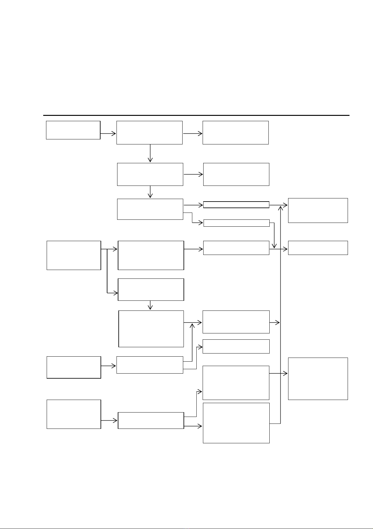
-Oil is a fluid and easily polluted. Keep it clean at all times.
-To protect the flow meter, a filter is installed between the pump and the
flow meter. If filter clogging occurs, the oil flow is get worse. Clean the
filter sometimes. (Fig. 7)
-The oil-proof hose is a consumable product. Check it periodically. If any
blemish or leakage is found, replace the hose a little earlier.
-The packing of the pump will be worn away. Check and replace it at
least once a year.
6. Disassembly and Assembly
-When the pump operation becomes defective or stops, do not disassemble the pump thoughtlessly, but refer to
the item on P.4 (Troubleshooting and Corrective Measures), and judge the condition carefully and disassemble
only the minimum necessary parts.
-The air motor is rarely touched directly, so its failure rate is very low. The air motor does not need to be
disassembled. If disassembling is required, ask the dealer to disassemble the air motor.
WARNING
- Gasoline is a high-volatility material. Do not use gasoline to clean the pump in any case, otherwise it
may cause ignition or explosion.
- Before starting disassembling or inspecting the machine, be sure to shut off the supply air and open
the outlet valve to release the internal pressure of the machine.
- When washing parts, do not use such a liquid as corrodes aluminum, copper alloy, iron, etc.
6.1 Disassembling the Air Motor and the Lower Pump
1) Shut off the air that is supplied to the pump and bleed the internal
pressure of the pump.
2) Remove the oil-proof hose and the air hose from the pump.
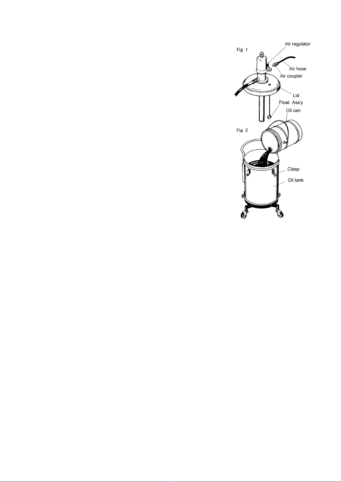
3) Release the 3 clasp on the top of the oil tank upward, and remove
the lid together with the pump.
4) Unscrew the 5 bolts (on the rear side of the lid) that fix the pump
Assy and the lid and separate the pump Assy from the lid.
Bleed the oil remaining in the tube by pushing up the ball in the
foot valve with a finger.
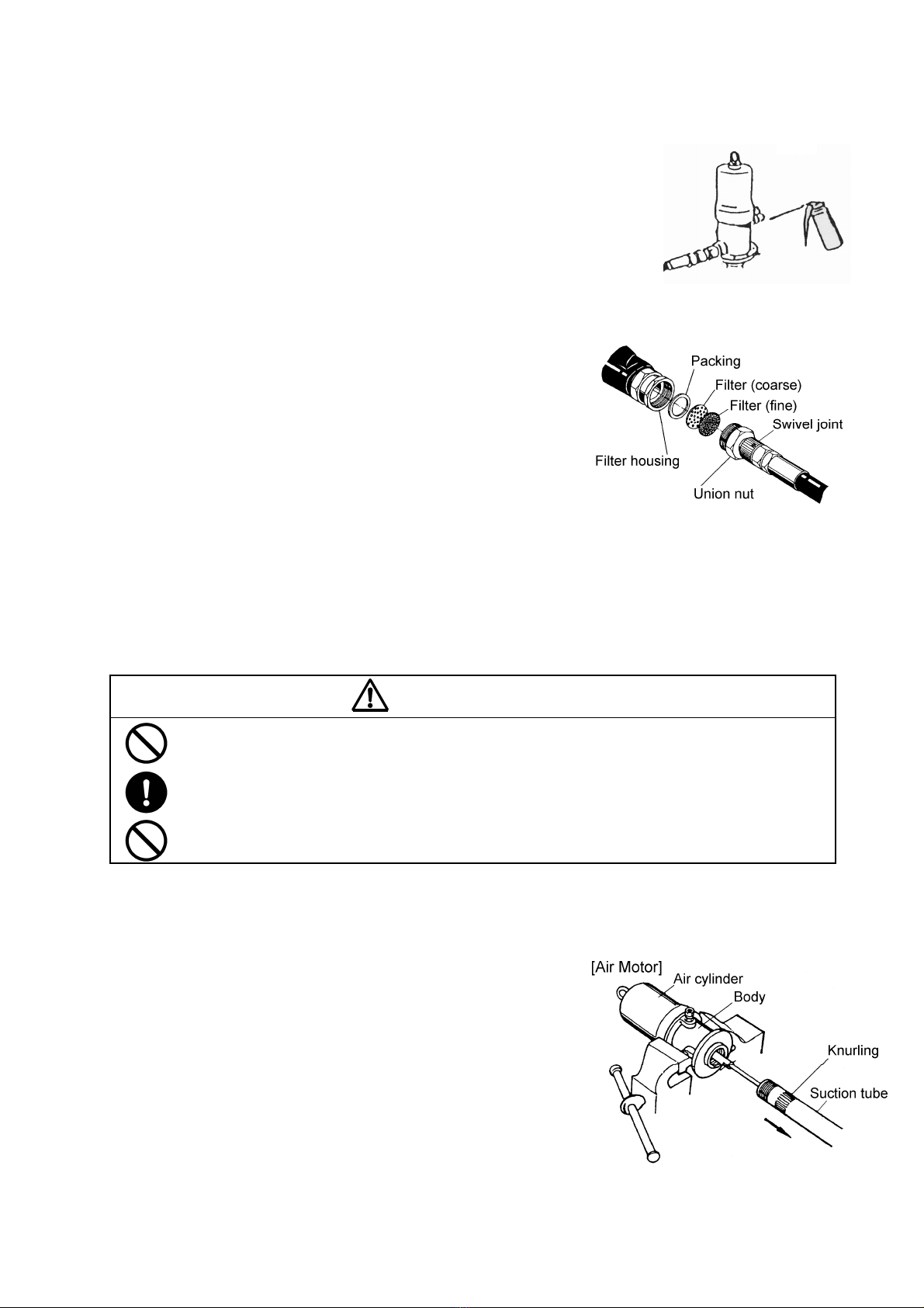
5) Fix the air motor body of the pump on the vise and set a pipe
wrench on the knurling section in the upper part of the suction
tube of the lower pump and unscrew it. (Fig. 8)
<NOTE>
The air cylinder is easily blemished. Do not fix it on the vise.
Fig.6
Fig.7
Fig.8

6
6) Pull out the suction tube, and the intake valve Assy becomes visible. At this time, take care not to cause the oil
remaining in the tube to flow on the floor. (Fig. 8)
6.2 Disassembling and Inspecting the Lower Pump
1) Set a pipe wrench on the knurling portion of the suction tube and
unscrew the foot valve. The foot valve is an assembly. (Fig. 9)
2) Pull out the spring pin between the piston rod and the connecting
rod, and the air motor can be detached.
3) Fix the housing of the intake valve Assy on the vise and set a
spanner on the valve body and unscrew it. The valve and the
U-packing can be disassembled. (Fig. 11)
4) Wash and check each disassembled part. If any blemish or wear
is found, replace the part with a new one.
5) Do not disassemble the housing and the connecting rod if possible.
If they are disassembled, assemble them so that the clearance
between the end of the connecting rod and the valve may be 3
mm, and then fix them with a locking nut. (Fig. 10)
6) For assembling, reverse the disassembling procedure and take
care about the up and down directions of the packing, etc.
6.3 Disassembling the air motor
-The air motor is not easily adjusted at assembly. If an air motor failure is found at maintenance and inspection,
ask the dealer to repair the air motor.
-For the user who intends to perform maintenance, the manual related to the disassembly and structure of the
motor is available as a separate volume. Ask the dealer for further information.
(Separately APP 001 U : Maintenance Manual for Oil Pump Type 110)

7
7. Parts Disassembly Drawing and Parts List
7.1 SGR-110A5 (880635)
7.2 PD-110A5 Pump Assy (851755)
<NOTE>
- If disassembly is required, ask the dealer to
disassemble the air motor.
- As for the specialist of the dissolution, refer
to the instruction manual.
(Separately APP 001U : Maintenance
Manual for Oil Pump Type 110 )
No. Parts No. Description Q'ty
1 802520 Air motor 1
2 632774 Spring pin 1
3 705577 Connecting rod 1
4 627016 Nut 1
5 705579 Housing 1
6 710925 Collar 1
7 686404 U-Packing 1
8 705580 Valve plate 1
9 710927 Valve seat 1
10 712018 Cylinder 1
11 683503 Nut 1
12 710912 Valve seat 1
13 712168 Collar 1
14 712175 Adapter 1
15 611101 Bolt 1
No. Parts No. Des cription Q'ty
1 851755 Pump Assy 1
2 682925 Air regulator 1
3 682924 Pressure gauge 1
4 680743 Air coupler 1
5 705582 Lid 1
6a 830112 Clasp 3
6b 701747 Pin cabinet 3
6c 680710 Snap pin 3
7 681769 Grounding conductor 1
8 680285 Hose adapter 1
9 695700 Hose 1
10 801151 Swivel joint 1
11 801428 Grip meter 1
12 801195 Non-drip hose 1
13 830745 Oil tank 1
14 830746 Base frame 1
15 680136 Caster 2
16 681767 Caster(with brake) 2
17 770532 Indicator 1
18 705593 Rod 1
19 770531 Float 1
- 790266 Caution-label 1
- 790677 Type & Model No-label 1

8
7.3 Grip Meter Assy (801428)
<NOTE>
If disassembly is required, ask the dealer to disassemble the Grip meter.
No. Parts No. Description
1 59628-001 Shroud Protector
2 58910-001 Shroud
3 55212-115 Screw, Shroud
4 59442-004 Knob Assembly, Preset
5 09665-002 Pointer, Inner Circle
6 711613 Dial Face
7 22602-002 Spring, Clutch Roller
8 04716-000 Clutch Roller
9 13560-000 Cam, ICP
11 18223-000 Gear, ICP
12 32593-000 Worm, UDP
13 59576-001 Setscrew, Worm
14 22562-006 Spacer
15 59310-001 Totalizer Assembly
16 55212-115 Screw, Totalizer Frame
17 59008-001 Packing Gland Kit, Buna N
18 13268-000 Cam, Standard, electronic
19 22872-001 Quad Ring, Buna N
20 58959-001 Screw, Sems Type
21 13263-001 Trigger Assembly, with lock
21 13259-002 Trigger Assembly, without lock
22 58618-001 Valve Assembly, Buna N
23 30099-000 Spring, Valve
24 58663-001 Screen
25 22973-002 Spindle, UDP
26 19438-003 Gear Train Assembly
27 19416-006 Chamber Complete
28 55300-223 O-Ring, Buna N
29 23686-002 Housing Cap, NPT Thrd
30 31132-051 O-Ring, Buna N
31 59648-001 Adapter Less Boss, NPT
Not
shown 62701-002 Viton Seal Upgrade Kit for
All Meters

9
8. Specification
8.1 Specification
8.2 Performance Curve (Only the pump) 8.3 Dimensions
<NOTE>
The continuous pump operation should be avoided if the
desired delivery is in the range shaded in the figure
below.
480
480
953
SGR-110A5
880635
5 x 1
FLUID CONNECTION DISCHARGE PORT Grip meter
AIR CONNECTION SUPPLY PORT Coupler plug(PS-20PM)
0.3 ~ 0.7 MPa
87.5 dB
ENV. TEMPERATURE 0 ~ 60 °C
MATER IAL TEMP. 0 ~ 8 0 °C
27.5 kg
Grip meter (801428)
Non-drip hose (801195)
Air regulator with coupler (802553)
Hose(695700)
ACCESSORIES
TYPE
MOD EL N o .
PUMP RATIO (NOMINAL)
OPERATING AIR PRESSURE
WEIGHT
AMB. TEMP. RANGE
MAXIMU M OP ER ATIN G N OIS E

10
9. Limited Warranty
If an abnormality occurs during normal operation in accordance with the operating instructions and other operating
cautions within the warranty period (12 months after date of purchase) that can be attributed to a manufacturing
defect, the defective parts of this product will be serviced or the product will be replaced free of charge. However, this
warranty will not cover compensation for incidental damage or any malfunction listed below.
1. Warranty period
This warranty will be valid for a period of 12 months after the date of purchase.
2. Warranty
If, during the warranty period, any of the material of the genuine parts of this product or the workmanship of this
product is found defective, and is so verified by our company, the servicing cost will be fully born by our company.
3. Exclusion
Even during the warranty period, this warranty does not cover the following.
1) Malfunction arising from use of parts other than manufacturer-specified genuine parts
2) Malfunction arising from misuse or operating errors, or lack of storage or maintenance care
3) Malfunction arising from use with a fluid that may cause corrosion, inflation or dissolution of the component
parts of the product
4) Irregularity arising from repair made by other than by our firm, our regional office, dealer or authorized service
personnel
5) Malfunction arising from modification of the product by other than authorized service personnel
6) Wear and tear of parts that must be regularly replaced in the course of normal operation, such as packings,
O-rings and hose.
7) Malfunction and/or damage due to use with incorrect voltage.
8) Malfunction and/or damage due to transportation, moving or drop page of the product after purchase
9) Malfunction and/or damage due to fire, earthquake, flood or other force majeure
10) Malfunction arising from use of compressed air that contains impurities or excessive moisture, or use of
gases or fluids other than the specified compressed air
11) Malfunction arising from use of excessively abrasive material or of inadequate grease.
Furthermore, this warranty does not cover the rubber parts, or other parts used in this product and its accessories,
which are subject to wear in normal operation.
・hoses ・packings ・cords
4. Parts
Parts for this product will be kept available for 5 years after discontinuation of production. Once 5 years have
elapsed after close of production, availability of parts for this product cannot be guaranteed.

YAMADA
EUROPE
B.V.
Aquamarijnstraat 50,7554 NS Hengelo (O),The Netherlands
PHONE : +31-(0)74-242-2032
FAX : +31-(0)74-242-1055
Manufactured by
YAMADA
CORPORATION
INTERNATIONAL DEPARTMENT
No.1-3, 1-Chome, Minami- Magome, Ohta-Ku, Tokyo, 143-8504, Japan
PHONE : +81-(0)3-3777-0241
FAX : +81-(0)3-3777-0584
201705 OSA012U
This manual suits for next models
1
Table of contents
Other YAMADA Lubrication System manuals