manuals.online logo
Brands
  1. Home
  2. •
  3. Brands
  4. •
  5. Graco
  6. •
  7. Lubrication System
  8. •
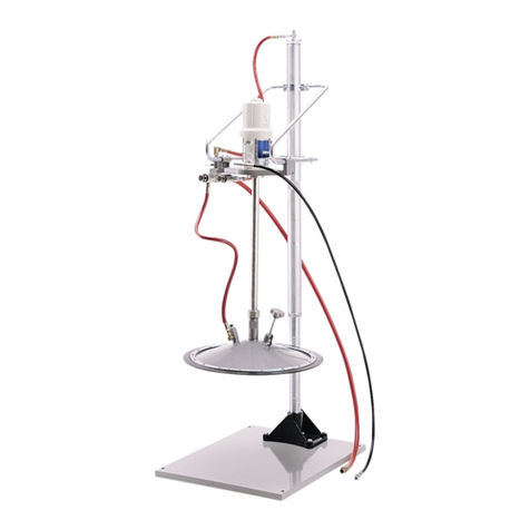
  9. Graco FIRE-BALL Series Operation manual

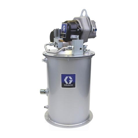
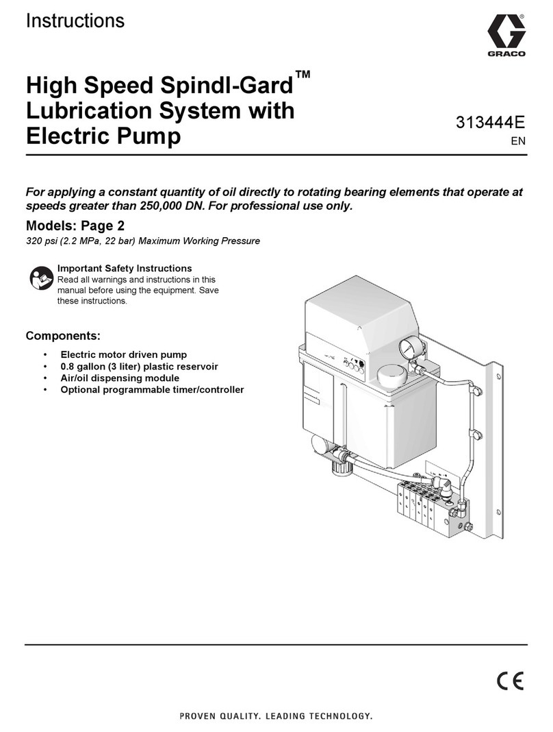
Graco FIRE-BALL Series Operation manual

Other manuals for FIRE-BALL Series

1

This manual suits for next models

5

Other Graco Lubrication System manuals

Graco Progressive Series User manual

Graco

Graco Progressive Series User manual

Graco Fire-Ball 425 Series User manual

Graco

Graco Fire-Ball 425 Series User manual

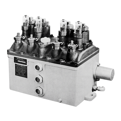
Graco Manzel HP-50 User manual

Graco

Graco Manzel HP-50 User manual

Graco 204867 User manual

Graco

Graco 204867 User manual

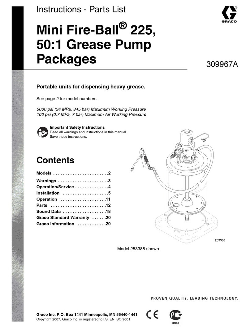
Graco Mini Fire-Ball 225 Series Operation manual

Graco

Graco Mini Fire-Ball 225 Series Operation manual

Graco G3 Series User manual

Graco

Graco G3 Series User manual

Graco Manzel HP-50 Guide

Graco

Graco Manzel HP-50 Guide

Graco 25 User manual

Graco

Graco 25 User manual

Graco 309015B Guide

Graco

Graco 309015B Guide

Graco 203-697 E Series Operation manual

Graco

Graco 203-697 E Series Operation manual

Graco 24Z764 User manual

Graco

Graco 24Z764 User manual

Graco 24Z764 User manual

Graco

Graco 24Z764 User manual

Graco 24W633 User manual

Graco

Graco 24W633 User manual

Graco GREASE JOCKEY User manual

Graco

Graco GREASE JOCKEY User manual

Graco Spindl-Gard 24B219 User manual

Graco

Graco Spindl-Gard 24B219 User manual

Graco FIRE–BALL 300 Air Motor Muffler Kit Operation manual

Graco

Graco FIRE–BALL 300 Air Motor Muffler Kit Operation manual

Graco FIRE-BALL Operation manual

Graco

Graco FIRE-BALL Operation manual

Graco GL-1 X Operation manual

Graco

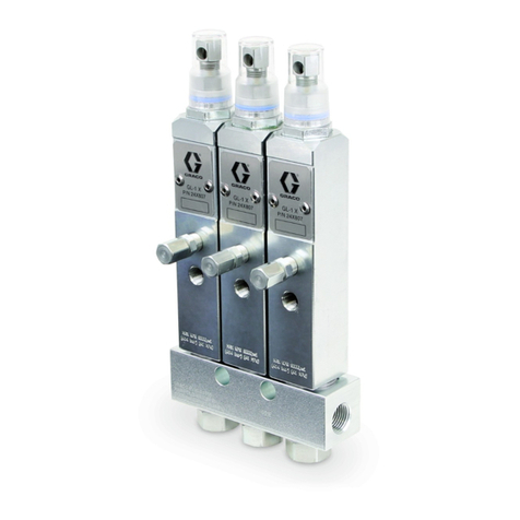
Graco GL-1 X Operation manual

Popular Lubrication System manuals by other brands

Atlanta BKI 109 e operating instructions

Atlanta

Atlanta BKI 109 e operating instructions

Viper Maxi MK 2 Assembly & operation manual

Viper

Viper Maxi MK 2 Assembly & operation manual

BEROTEC Mofessor manual

BEROTEC

BEROTEC Mofessor manual

Pressol PNEUMAxx operating instructions

Pressol

Pressol PNEUMAxx operating instructions

Lincoln QLS 421 Installation and operating instructions

Lincoln

Lincoln QLS 421 Installation and operating instructions

AUTOL ALP01 Series installation manual

AUTOL

AUTOL ALP01 Series installation manual

MEMOLUB HPS installation instructions

MEMOLUB

MEMOLUB HPS installation instructions

Perma PRO 250 operating instructions

Perma

Perma PRO 250 operating instructions

YAMADA SKR-55 880870 Instruction

YAMADA

YAMADA SKR-55 880870 Instruction

SKF LUBRILEAN Basic operating manual

SKF

SKF LUBRILEAN Basic operating manual

iSHAN YET-A1 Operation instructions

iSHAN

iSHAN YET-A1 Operation instructions

SKF UFD20 Series Assembly instructions

SKF

SKF UFD20 Series Assembly instructions

Groeneveld Multiline AC Series installation manual

Groeneveld

Groeneveld Multiline AC Series installation manual

MATO eHybrid-Greaser 230V operating instructions

MATO

MATO eHybrid-Greaser 230V operating instructions

Timken M-Power 300 installation instructions

Timken

Timken M-Power 300 installation instructions

MEMOLUB HPS instructions

MEMOLUB

MEMOLUB HPS instructions

IMI norgren Micro-Fog L68C Installation & maintenance instructions

IMI

IMI norgren Micro-Fog L68C Installation & maintenance instructions

Bijur Delimon L18P manual

Bijur Delimon

Bijur Delimon L18P manual

manuals.online logo
manuals.online logoBrands
  • About & Mission
  • Contact us
  • Privacy Policy
  • Terms and Conditions

Copyright 2025 Manuals.Online. All Rights Reserved.

Instructions – Parts List
GRACO INC.ąP.O. BOX 1441ąMINNEAPOLIS, MNą55440-1441
Copyright 1996, Graco Inc. is registered to I.S. EN ISO 9001
50:1 Fire-Ball
,50:1 President, and 75:1 President
400-lb. drum size
Topper Units 306556R
For use with lubricating products only.
Model 226013, 50:1 Ratio Fire-BallPump
5000 psi (34.5 MPa, 350 bar) Maximum Fluid Working Pressure
100 psi (0.7 MPa, 7 bar) Maximum Air Pressure
Model 226018, 50:1 Ratio PresidentPump
4000 psi (28 MPa, 280 bar) Maximum Fluid Working Pressure
80 psi (0.6 MPa, 5.6 bar) Maximum Air Pressure
Model 244637, 75:1 Ratio PresidentPump
4000 psi (28 MPa, 280 bar) Maximum Fluid Working Pressure
80 psi (0.6 MPa, 5.6 bar) Maximum Air Pressure
Model 204490, Elevator and Inductor
without pump or hose kit
0719
Important Safety instructions
Read all warnings and instructions in this manual.
Save these instructions.
2 306556
Table of Contents
Warnings 2. . . . . . . . . . . . . . . . . . . . . . . . . . . . . . . . . . . . . .
Installation 6. . . . . . . . . . . . . . . . . . . . . . . . . . . . . . . . . . . . .
Operation 10. . . . . . . . . . . . . . . . . . . . . . . . . . . . . . . . . . . .
Troubleshooting 11. . . . . . . . . . . . . . . . . . . . . . . . . . . . . . .
Service 12. . . . . . . . . . . . . . . . . . . . . . . . . . . . . . . . . . . . . .
Parts 13. . . . . . . . . . . . . . . . . . . . . . . . . . . . . . . . . . . . . . . .
Dimensions 18. . . . . . . . . . . . . . . . . . . . . . . . . . . . . . . . . . .
Sound Data 19. . . . . . . . . . . . . . . . . . . . . . . . . . . . . . . . . . .
Graco Standard Warranty 20. . . . . . . . . . . . . . . . . . . . . .
Graco Phone Number 20. . . . . . . . . . . . . . . . . . . . . . . . . .
Symbols
Warning Symbol
WARNING
This symbol alerts you to the possibility of serious
injury or death if you do not follow the instructions.
Caution Symbol
CAUTION
This symbol alerts you to the possibility of damage to
or destruction of equipment if you do not follow the
instructions.
WARNING
EQUIPMENT MISUSE HAZARD
Equipment misuse can cause the equipment to rupture or malfunction and result in serious injury.
This equipment is for professional use only.
Read all instruction manuals, tags, and labels before operating the equipment.
Use the equipment only for its intended purpose. If you are not sure, call your Graco distributor.
Do not alter or modify this equipment.
Check equipment daily. Repair or replace worn or damaged parts immediately.
Do not exceed the maximum working pressure stated on the equipment or in the Technical Data
for your equipment. Do not exceed the maximum working pressure of the lowest rated component
in your system.
Use fluids and solvents which are compatible with the equipment wetted parts. Refer to the Tech-
nical Data section of all equipment manuals. Read the fluid and solvent manufacturer’s warnings.
Handle hoses carefully. Do not pull on hoses to move equipment.
Route hoses away from traffic areas, sharp edges, moving parts, and hot surfaces. Do not expose
Graco hoses to temperatures above 66C (150F) or below –40C (–40F).
Wear hearing protection when operating this equipment.
Do not move or lift pressurized equipment.
Comply with all applicable local, state, and national fire, electrical, and safety regulations.
3306556
WARNING
SKIN INJECTION HAZARD
Spray from the gun, leaks or ruptured components can inject fluid into your body and cause extremely
serious injury, including the need for amputation. Fluid splashed in the eyes or on the skin can also
cause serious injury.
Fluid injected into the skin is a serious injury. The injury may look like just a cut, but it is a serious
injury. Get immediate surgical treatment.
Do not point the gun at anyone or at any part of the body.
Do not put your hand or fingers over the spray tip.
Do not stop or deflect leaks with your hand, body, glove, or rag.
Do not “blow back” fluid; this is not an air spray system.
Always have the tip guard and the trigger guard on the gun when spraying.
Check the gun diffuser operation weekly. Refer to the gun manual.
Be sure the gun trigger safety operates before spraying.
Lock the gun trigger safety when you stop spraying.
Follow the Pressure Relief Procedure on page 6 if the spray tip clogs and before cleaning,
checking, or servicing the equipment.
Tighten all fluid connections before operating the equipment.
Check the hoses, tubes, and couplings daily. Replace worn, damaged, or loose parts immediately.
Permanently coupled hoses cannot be repaired; replace the entire hose.
MOVING PARTS HAZARD
Moving parts can pinch or amputate your fingers.
Keep clear of all moving parts when starting or operating the pump.
Before checking or servicing the equipment, follow the Pressure Relief Procedure on page 6 to
prevent the equipment from starting unexpectedly.
4 306556
WARNING
FIRE AND EXPLOSION HAZARD
Improper grounding, poor ventilation, open flames, or sparks can cause a hazardous condition and
result in a fire or explosion and serious injury.
Ground the equipment and the object being sprayed. Refer to Grounding on page 6.
If there is any static sparking or you feel an electric shock while using this equipment, stop spray-
ing immediately. Do not use the equipment until you identify and correct the problem.
Provide fresh air ventilation to avoid the buildup of flammable fumes from solvents or the fluid
being sprayed.
Keep the spray area free of debris, including solvent, rags, and gasoline.
Do not smoke in the spray area.
TOXIC FLUID HAZARD
Hazardous fluid or toxic fumes can cause serious injury or death if splashed in the eyes or on the skin,
inhaled, or swallowed.
Know the specific hazards of the fluid you are using.
Store hazardous fluid in an approved container. Dispose of hazardous fluid according to all local,
state, and national guidelines.
Always wear protective eyewear, gloves, clothing, and respirator as recommended by the fluid and
solvent manufacturer.
5306556
Notes
6 306556
Installation
NOTE: Reference numbers and letters in parentheses
in the text refer to the callouts in the figures and the
parts drawing.
NOTE: Always use Genuine Graco Parts and
Accessories, available from your Graco distributor.
Grounding
WARNING
FIRE AND EXPLOSION HAZARD
Before operating the pump, ground the
system as explained below. Also read
the section FIRE OR EXPLOSION HAZ-
ARD on page 4.
Pump: Use a ground wire and clamp as shown in
Fig.1.
Air, and fluid hoses: Use only electrically conductive
hoses.
Air compressor: Follow manufacturer’s
recommendations.
Spray gun and dispensing valve: Ground through
connection to a properly grounded fluid hose and
pump.
Fluid supply container: Follow your local code.
Truck bed or platform: Follow your local code.
Solvent pails used when flushing: Follow your local
code. Use only metal pails, which are conductive,
placed on a grounded surface. Do not place the pail
on a nonconductive surface, such as paper or
cardboard, which interrupts the grounding
continuity.
To maintain grounding continuity when flushing or
relieving pressure, hold a metal part of the
dispensing valve firmly to the side of a grounded
metal pail, then trigger the valve.
To ground the pump, remove the ground screw (Z)
and insert through the eye of the ring terminal at the
end of ground wire (Y). Fasten the ground screw back
onto the pump and tighten securely. Connect the other
end of the ground wire to a true earth ground. See Fig.
1. To order a ground wire and clamp, order Part No.
222011.
Fig. 1 TI1052
Y
Z
Pressure Relief Procedure
WARNING
SKIN INJECTION HAZARD
Fluid under high pressure can be in-
jected through the skin and cause
serious injury. To reduce the risk of an
injury from injection, splashing fluid, or moving
parts, follow the Pressure Relief Procedure
whenever you
Are instructed to relieve the pressure
Shut off the pump
Check or service any of the system equipment
1. Close the pump’s air regulator
2. Close the supply pump’s bleed-type master air
valve (required in this system).
3. Hold a metal part of the dispensing valve firmly to
a grounded metal waste container and open the
dispensing valve until pressure is fully relieved.
If you suspect that the dispensing valve, extension, or
grease fitting coupler is clogged, or that pressure has
not been fully relieved after following the steps above,
VERY SLOWLY loosen the coupler or hose end
coupling and relieve pressure gradually, then loosen
completely, then clear the clog.
7306556
Installation
0721
mounting
holes
5’ (1524 mm)
supply lines
(through wall)
bleed-type
master air valve
high pressure
fluid shutoff valve
supply lines
(from ceiling)
3” (76 mm)
1” (25 mm)
6” (152.4 mm)
clearance
for plumbing
The Typical Installation shown above is only a guide
for selecting and installing this system. It is not an
actual system design. Contact your Graco
representative for assistance in designing a system to
suit your particular needs.
Positioning the Elevator
1. Position the elevator where the ceiling is at least
8 ft. (2.6 m) high. The elevator is 90 in. (2.4 m)
when fully raised; complete dimensions are shown
on page 18.
2. Provide adequate space in front of the elevator for
changing drums and in back and on the side for
plumbing.
Mounting the Elevator
1. Secure the elevator base (A) to the mounting base
(102), using the screws (104), lockwashers (103),
and nuts (105). See Fig. 3.
2. Bolt the mounting base (102) to the floor for
stability.
3. Be sure that the elevator is level. Loosen one or
two screws (104) on the elevator base and place
shims under the base, if necessary.
4. Place the inductor plate (2, 18, or 22) on the
mounting base (102).
5. Loosen the screws (68) of both support brackets
(83). Slide the support (64) down far enough to
allow installation of the pump in the inductor plate.
Tighten the bracket screws lightly.
8 306556
Installation
Mounting the Pump
Models 226013, 226018, and 244637
1. Mount the pump on pump support bracket (86).
2. Remove inductor plate nut (11 or 24), locking
ring (8 or 23) and O–ring (9). See Fig. 3.
3. In order, slide inductor plate nut (11 or 24), locking
ring (8 or 23) and O–ring (9) on pump riser tube.
4. Adjust the inductor plate on the pump so that the
pump intake is 0.12 in. (3.2 mm) above the
mounting base. Tighten the locknut (11 or 24)
securely. See Fig. 3 Detail. Continue with step 4
below.
NOTE: The full length of the pump intake slots must
be just below the bottom of the inductor cone as
shown in Fig. 3 Detail.
Model 204490
1. Lubricate the o-ring (20) in the inductor plate (18)
with light, waterproof grease. See Fig. 2.
2. Mount the pump on the pump support (64) so the
fluid outlet faces front. See Fig. 3.
3. Guide the pump intake valve as far as possible
into the inductor plate, then tighten the set-
screws (19). Continue with step 4 below.
All Models
4. Loosen the pump support clamps again and raise
the support (64) until it meets the pump base.
5. Secure the President or Fire-Ball pump to the
pump support mounting plates from the underside
with the screws.
6. Tighten screws (68) on lower pump bracket (83).
7. Slide the upper support bracket (83) up or down
(the tubing of the pump support [64] will flex
slightly) until the pump is in a true vertical position.
Tighten the screws (68) on the upper bracket.
0724
Fig. 2
18 20 19
0723
Fig. 3
DETAIL
0.12” (3.2 mm)
pump intake
slots
11 or 24
pump riser
tube
8 or 23
2 or 22
INDUCTOR PLATE for
Models 226013, 226018, and 244637
90
A
41
61
62
10
47
27
65
86 91 or 97
83 73
64
68
62 89 85
104,
103,
105 E102
2, 18, or 22
11 or 24
0722A
9306556
Installation
Installing the Hoses and Valves
NOTE: Use thread sealant on all male threads except
at the swivel unions.
1. Remove the plug from the top of the elevator cap,
and screw it into the air inlet (E) in the elevator
base. Screw the restrictor valve assembly (42) into
the elevator cap.
2. Screw the 1/4 x 1/8 npt adapter (85) into the
restrictor valve. Install the 1/4 x 3/8 npt adapter
(89). Connect one end of the 36 in.
(914 mm) hose into the adapter and the other hose
end into the snap-over valve’s (27) union (82).
Route the hose inside the arms of the pump
support (64) as shown in Fig. 3.
3. Screw the hex nipple (115 or 99) from the outlet
hose kit (91 or 97) to the pump outlet. Connect the
kit’s swivel union (96) to the adapterwith the
opening in the valve (94) facing down. Refer to the
Hose Kit parts drawing on page 18.
4. Install a bleed-type master air valve on the pump’s
air supply line. See the Typical Installation on
page 7.
WARNING
The bleed-type master air valve is required in your
system to relieve air trapped between this valve
and the pump after the air is shut off. Trapped air
can cause the pump to cycle unexpectedly and
cause serious injury, including splashing in the
eyes or on the skin. Position the valve close to the
pump.
5. Install a fluid shutoff valve on the fluid supply line
to shut off fluid to the pump.
6. Finish assembling the hoses and fittings as shown
in Fig. 3 and the Parts Drawing on
page 16.
10 306556
Operation
CAUTION
Always close the ball valve (65) as soon as the
inductor plate reaches the bottom of the drum,
indicating the drum is empty. Allowing the pump to
run without fluid will cause damage to the pump.
Installing a Drum
WARNING
To reduce the risk of serious injury whenever you
are instructed to relieve pressure, always follow the
Pressure Relief Procedure on page 6.
1. Relieve the Pressure.
2. Close the ball valve (65). The handle will be at a
90angle to the valve body.
3. Open the bleed-type master air valve (F).
4. Open the inductor plate vent by turning the
knob (10) counterclockwise.
5. Pull open the snap-over valve (27) to raise the
elevator.
NOTE: To adjust the elevator speed, turn the restrictor
valve screw (46) clockwise to decrease the speed or
counterclockwise to increase it.
6. Center an opened 400 pound drum under the
inductor plate so the drum bottom touches the
elevator base (A).
7. Make the top of the fluid concave by scooping fluid
from the center to the sides of the container.
8. Loosen the setscrews (73), holding pump
mounting plates to the mounting bracket (C). Align
the pump and inductor plate with the drum.
WARNING
Keep your fingers and hands away from the
sides of the drum or inductor plate to avoid
pinching them when raising and lowering the
pump.
9. Push in the snap-over valve (27) to lower the
pump while guiding the inductor plate into the
drum.
10. Press down on the pump and rock it back and
forth to seat the inductor plate. This helps
eliminate air trapped beneath the plate. Continue
this action until fluid appears at the vent
opening (D).
11. Be sure that the pump is aligned vertically, and
tighten the setscrews (73).
12. Close the inductor plate vent by turning the
knob (10) clockwise.
13. For Models 226013, 226018, and 244637 only:
Open the bleeder valve (94) at the pump outlet by
turning the thumbscrew counterclockwise. Open
the ball valve (65) until all air trapped in the pump
and under the plate are pumped through the valve.
Close the ball valve and the bleeder valve.
Regulate the pump speed with the ball valve
handle.
14. All Models: Always use the lowest possible pump
pressure necessary for good delivery. Higher
pressures cause premature pump wear and
usually do not produce better results.
Fig. 4
F
65
A
73
46
91
See hose kits
on page 18.
D
10
C27
47
0725B
94