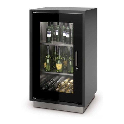
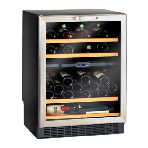
Enofrigo MIAMI B&R Programming manual

Code CT36900002_(MIAMI USA)_EN - 06/2018 - R02
International style
with Italian flavour
MIAMI MEDIUM MIAMI MINIMIAMIMIAMI B&R
INSTRUCTIONS FOR INSTALLATION,
OPERATION AND MAINTENANCE
MIAMI
Read this manual carefully before installing and using the product. Keep this manual with the product for future reference.
Refrigerated wine bottle display
cabinets
EN (USA)
Code

2
INTRODUCTION
Dear Customer,
Thank you for purchasing a product from
Enofrigo
.
The
MIAMI
model you have purchased is a high performance product characterised by advanced design and technology and excel-
lent reliability and quality.
We recommend that you entrust its maintenance and servicing to a qualified professional of your choice and insist on the use of
original spare parts, if required.
This manual contains important information and instructions that must be followed in order to install and operate the product cor-
rectly and efficiently.
RANGE
This manual refers to the following products:
MODEL CODE NEW CODE
MIAMI MINI T VT (TUBES) A1MIAMIMINIU/* MMINIU*
MIAMI MINI DR VT (DRAWERS) A1MIAMIMINIDRU/* MMINIDRU*
MIAMI MINI SH VT (SHELVES) A1MIAMIMINISHU/* MMINISHU*
MIAMI MEDIUM T VT (TUBES) A1MIAMIMEDVTU/* MMEDVTU*
MIAMI MEDIUM DR VT (12 DRAWERS) A1MIAMIMEDDRFVTU/* MMEDDRFVTU*
MIAMI MEDIUM MIX VT (2 TUBES 3 DRAWERS) A1MIAMIMEDMIXVTU/* MMEDMIXVTU*
MIAMI MEDIUM SH VT (SHELVES) A1MIAMIMEDSHVTU/* MMEDSHVTU*
MIAMI T VT (TUBES) A1MIAMIVTU/* MVTU*
MIAMI DR F VT (12 DRAWERS) A1MIAMIDRFVTU/* MDRFVTU*
MIAMI SH VT (SHELVES) A1MIAMISHVTU/* MSHVTU*
MIAMI MIX VT (2 TUBES 3 DRAWERS) A1MIAMIMIXVTU/* MMIXVTU*
MIAMI B&R T VT (TUBES) A1MIAMIBRVTU/* MBRVTU*
MIAMI B&R DR F VT(12 DRAWERS) A1MIAMIBRDRFVTU/* MBRDRFVTU*
MIAMI B&R MIX VT (2 TUBES 3 DRAWERS) A1MIAMIBRMIXVTU/* MBRMIXVTU*
MIAMI B&R SH VT (SHELVES) A1MIAMIBRSHVTU/* MBRSHVTU*
/* = # COLOUR
SYMBOLS USED IN THIS MANUAL AND THEIR MEANINGS
IMPORTANT!
Indicates particularly important information.
CAUTION!
Indicates particularly important or delicate operations.
WARNING!
Indicates actions that, if not performed correctly, may lead to accidents of a generic nature or cause malfunctioning or
damage to the product, and therefore require particular care and adequate preparation.
WARNING! RISK OF ELECTROCUTION!
Indicates actions that, if not performed correctly, may lead to electrical accidents and therefore require particular care and
adequate preparation.
STOP!
Indicates actions that MUST NOT be done.

3
CONTENTS
WARRANTY
This
Enofrigo
product benefits from a
conventional warranty
, valid from the date of purchase. The terms of this warranty are specified
in the GENERAL CONDITIONS OF SALE published on the website www.enofrigo.com.
CAUTION!
–The warranty is invalidated if the instructions provided in this manual are not followed.
–The warranty is also invalidated if the customer modifies the product or has others modify it without the approval of the
manufacturer or an authorised dealer or attempts to make repairs to the product himself.
–The product must only be used for the purpose for which it has been expressly designed and made by
Enofrigo
.
Enof-
rigo
cannot accept any responsibility, contractual or otherwise, for injury to persons or animals or damage to property
deriving from incorrect installation, operation, settings or maintenance.
1 General 4
1.1 General warnings and safety precautions 4
1.2 STOP! 4
1.3 Description of the appliance 5
1.4 Identification 5
1.5 Structure 6
1.6 Safety devices 7
1.7 Control panel 7
2 Installation 8
2.1 Receiving the product 8
2.2 Dimensions and weight 8
2.3 Place of installation 9
2.4 Installation 11
2.4.1 Moving 11
2.4.2 Fixing to the floor 11
2.4.3 Fitting the handle 13
3 Operation 14
3.1 Preliminary steps 14
3.1.1 Checks 14
3.1.2 Connecting to the electricity supply 14
3.2 Putting into service 15
3.2.1 Display indications 15
3.2.2 Changing the temperature setpoint 15
3.2.3 Defrosting 15
3.2.4 Restoring default settings 16
3.3 List of "F" parameters and possible settings 16
3.2.5 Turning the electronic controller ON/OFF 16
3.4 Alarm codes and resetting 17
3.4.1 Cancelling manual reset alarms 18
3.4.2 Resetting HACCP alarms 18
3.5 Interior equipment 18
3.5.1 Temperature distribution 18
3.6 Switching off 19
3.6.1 Switching off temporarily 19
3.6.2 Switching off for extended periods 19
4 Maintenance 20
4.1 Good practice 20
4.2 External cleaning 20
4.3 Cleaning the interior and important parts 20
4.3.1 Cleaning the interior of the cabinet 21
4.4 Regular checks 21
4.5 Extraordinary maintenance 21
4.6 Problems - Possible causes - Solutions 22
4.7 Technical assistance and spare parts 23
4.8 Disposal 23
5 Appendices 24
5.1 Functional electrical diagram 24
5.2 Declaration of conformity 26

4
1 GENERAL
1.1 General warnings and safety precautions
IMPORTANT!
–This manual is the intellectual property of
Enofrigo
. Copying its contents or transmitting them to others is strictly for-
bidden. All rights reserved. This manual is an integral part of the appliance. It must accompany the appliance at all times,
even if the appliance is sold or transferred to another owner, so that it can be consulted by the user or person responsible
for servicing or repair.
–Read this manual thoroughly before using the appliance in order to ensure safe operation.
–The appliance is delivered in a single pack. Check immediately that the appliance received conforms to the order, and
report any discrepancy to the local dealer from whom it was purchased.
–Report any damage to the appliance's packing to the carrier and supplier.
–This appliance is designed and made to cool drinks.
Enofrigo
cannot accept any responsibility, contractual or otherwise,
for injury to persons or animals or damage to property deriving from incorrect installation, operation, settings or main-
tenance.
–The appliance is not designed for installation and use in places where it is exposed to the weather.
–If you have any doubts concerning operating conditions and/or the functioning of the appliance or any of its component
parts, contact your local dealer for clarifications.
–If you notice any problems or malfunctions when you put the appliance into service, report them immediately to the
dealer who sold it.
–Check the condition of the power cable, plug and socket at regular intervals.
–If you are not going to use the appliance for an extended period of time, perform the following operations:
-Turn the appliance's main power switch “OFF”
-Remove the plug from the power socket. If the plug cannot be accessed easily, disconnect power to the socket to which the
appliance is connected by means of a double pole switch
-Empty the cabinet and clean all internal parts with a cloth damped in water or a neutral detergent.
–When the appliance is functioning, take care not to touch any steel surfaces inside the cabinet with wet or damp hands
as your skin could stick to the cold surface.
–Only load drinks that are already cooled or at least not hot into the cabinet.
–Only use original spares or parts approved by the manufacturer. Use of other parts may damage the appliance.
1.2 STOP!
STOP!
–Do not modify or attempt to repair the appliance yourself. All repairs must be referred to a qualified technician.
–Do not store flammable materials inside or near the appliance.
–Do not use electrical equipment of any kind inside the cabinet.
–Do not expose the appliance to the weather.
–Do not touch the appliance with damp or wet hands or while standing in bare feet. If you experience an electrical shock
on contact with a metal surface of the appliance, turn it off at the switch, disconnect the plug from the power socket and
contact an authorised dealer immediately.
–Do not allow children, differently able persons or persons with insufficient experience or knowledge to operate the ap-
pliance unless supervised by somebody who is suitably qualified and responsible for their safety.
–Do not dispose of packing material into the environment or leave it within reach of children as it can become a hazard.
Dispose of packing materials in accordance with applicable legislation.

5
1.3 Description of the appliance
MIAMI
refrigerated cabinets are extremely versatile units that represent the latest development in wine display. Excellent internal illu-
mination focuses attention on the bottles of wine stored inside. LED light units and a cleverly designed interior create an impression
of depth and produce reflections of light that enhance the presentation of bottles of wine.
Energy consumption is minimal thanks to LED lighting. Low noise and optimised functioning are guaranteed by a refrigeration system
with an automatic controller. The cabinet is also extremely efficient thanks to thick insulation and low emission double glazed doors.
Bottle display is particularly flexible: steel tubes can be fitted to display bottles reclined or even horizontal, and elegant wooden draw-
ers can also be used.
The static refrigeration version permits four different temperatures to be achieved within the same cabinet. This allows one cabinet to
be used for both red and white wines. The ventilated refrigeration version lets you select a uniform storage temperature.
A wide range of models is available to satisfy different space requirements, and to display different quantities of wine in different ways.
The range is divided into four sizes: MIAMI MINI, MIAMI MEDIUM, MIAMI and MIAMI B&R. Each size can be fitted with different internal
equipment: tubes (T), drawers (DR), shelves (SH) and mixed (MIX) (mixed is not available for MIAMI MINI).
1.4 Identification
MIAMI
refrigerated display cabinets are identified by a nameplate. The nameplate is located inside the cabinet, as shown in Fig. 1, and
declares the appliance's technical and performance and other mandatory details.
2
1
3
4
5
6
1
CE mark
2
Identity of manufacturer
3
Type of appliance
4
Serial number
5
Model
6
Technical specifications
Fig. 1
IMPORTANT!
If the nameplate or any other identifying information is defaced, removed or missing, correct installation and maintenance
of the appliance may be compromised.

6
1.5 Structure
1
15
16
17
9
11
10
19
18
8
7
6
5
14 13 12
4
2
3
MIAMI
MEDIUM
MIAMI
MINI
MIAMIMIAMI
B&R
1
Door
2
Handle
3
Lock
4
Glass
5
Base
6
LED light
7
Evaporator panel
8
Shelves
9
Structure
10
Fan switch (*)
11
Fan cover
12
Main switch
13
Control panel
14
Fan protection grille
15
Condenser coil
16
Adjustable flanged feet
17
Power cable and plug
18
Condensate collection tank
19
Motor protection grille
(*) Not available for MIAMI MINI models.
Fig. 2

7
1.6 Safety devices
MIAMI
refrigerated display cabinets are equipped with the following safety devices:
–Motor protection grille
–Fan protection grille
–Flanged feet for fixing to the floor
1.7 Control panel
13 2
1
MAIN SWITCH
2
FUNCTION KEYS
pPress for more than 5 s on power-up to access the pro-
cedure for resetting default parameters.
Press in conjunction with p+ufor more than 3 s to
cancel all manual reset alarms.
sPress for more than 1 s to view and/or change the tem-
perature setpoint. Press for more than 5 s to start man-
ual defrosting.
uPress for more than 3 s to switch the controller OFF.
Press for more than 1 s to switch the controller ON. In
parameter setting mode, press to increment the dis-
played value.
dPress for more than 1s to switch internal lighting on/
off. In parameter setting mode, press to decrement the
displayed value.
3
DISPLAY
0Compressor
ON: on. OFF: off. Flashing: standby.
1Fan
ON: on. OFF: off. Flashing: standby.
2Defrosting
ON: on. Flashing: standby.
5Light
ON: auxiliary power output (1 and/or 2) configured as
light on.
7HACCP
ON: HACCP function active. Flashing: HACCP alarm
logged (HA and/or HF).
8Service
ON: PROGRAMMING function active. Flashing: error/s
detected, e.g. EEPROM or sensor errors.
Fig. 3

8
2 INSTALLATION
2.1 Receiving the product
MIAMI
appliances are delivered in a single pack, inside a cardboard box.
1
1
The following material is also supplied, inside the cabinet:
–Installation, operation and maintenance manual
–Door handle and fixing screws
–Keys for the door lock
–Tubes for reclining bottle displays (cradles, shelves and drawers are pre-in-
stalled in the cabinet)
This manual is an integral part of the appliance. Read it thoroughly be-
fore installing the appliance or putting it into service. Keep it with the
appliance for future consultation and transfer it to any new owner or
user along with the appliance.
Fig. 4
STOP!
Do not dispose of packing material into the environment or leave it within reach of children as it can become a hazard.
Dispose of packing materials in accordance with applicable legislation.
2.2 Dimensions and weight
MIAMI B&R MIAMI MIAMI MEDIUM
MIAMI MINI
LD
H
LD
H
LD
H
LD
H
Fig. 5
Description MIAMI B&R MIAMI MIAMI MEDIUM MIAMI MINI
L (in-mm) 48 / 1220 32 1/4 - 820 24 - 610 24 - 610
D (in-mm) 19 3/4 - 500 19 3/4 - 500 19 3/4 - 500 19 3/4 - 500
H (in-mm) 77 1/2 - 1970 77 1/2 - 1970 77 1/2 - 1970 51 1/4 - 1300
Weight (lbs-kg) 540 - 245 330 - 150 276 - 125 110 - 50

9
2.3 Place of installation
The place of installation must conform to all applicable technical and health standards. Position the appliance in a dry, well ventilated
place. In particular:
–Do not position the appliance near sources of heat (radiators, ovens, cookers, etc.) or in draughts.
–Do not expose the appliance to direct sunlight.
When installing a
MIAMI
appliance as a replacement for an older product, perform the following checks:
–Check that the electrical power supply has been installed by a qualified electrician in conformity to applicable standards
–Check that the place of installation conforms to all applicable technical and health standards.
IMPORTANT!
To ensure optimal functioning of the appliance, the place of installation must conform to the following conditions:
–ambient temperature = 86°F (30°C)
–RH (relative humidity) = 55%
–climate class = 4.
IMPORTANT!
In installations at altitudes over 2950 feet (900 metres), a compensation valve must be installed in each double glazing
compartment. This must be specified AT THE TIME OF ORDER.
STOP!
–Do not use the appliance in places where there is a risk of fire/explosion due to the presence/development of dusts,
gases or flammable mixtures.
–Do not store flammable materials inside or near the appliance.
–Do not expose the appliance to the weather.
IMPORTANT!
Bear in mind the space necessary to access the various safety/control devices and power plug, also the space needed for
maintenance and proper ventilation (see Fig. 7).
F
ORBIDDEN positions
NO!
Narrow niche
Back against wal
l
NO!
I II
Fig. 6

10
C
AA
D
PERMITTED positions
B
I
A A
II
C
D
Fig. 7
Description MIAMI B&R MIAMI MIAMI MEDIUM MIAMI MINI
A (in-mm) 8 - 200 8 - 200 8 - 200 8 - 200
B (in-mm) 6 - 150 6 - 150 6 - 150 6 - 150
C (in-mm) 8 - 200 8 - 200 8 - 200 8 - 200
D (in-mm) 42 1/4 -1075 50 1/2 - 1280 42 1/4 -1075 42 1/4 -1075

11
2.4 Installation
2.4.1 Moving
Once the appliance has been removed from its packing, proceed as follows to move it into position:
–Move the appliance near the place of installation
–Pull out the drip tray (1) from the rear of the appliance, taking care not to damage the cable (2)
–Steer the forks (3) of a pallet transporter under the appliance, lift it just clear of the floor and remove the pallet (4)
–Lower the appliance back on to the floor and replace the drip tray (1), taking care guide the cable (2) back into its original position.
WARNING!
While moving the appliance, take great care to prevent it falling over.
1
21
2
3
4
Fig. 8
2.4.2 Fixing to the floor
IMPORTANT!
Appliance must be securely attached to the floor! Carefully follow the instructions below.
–Remove the screws (5) and remove the base (6) from the front
–Move the appliance into its final installation position, proceeding in small steps at a time
–Level off the appliance using the adjustable feet. Make sure that the door opens fully and smoothly (check all doors on multi-door
models)
–Mark the position of the holes in the foot flanges (7) on the floor
5
6
5
7
Fig. 9

12
–Move the appliance away from its final installation position, proceeding in small steps at a time
–Drill holes in the floor at the points marked and fit expansion bolts (8) (not supplied)
8
Fig. 10
–Move the appliance into its final installation position, proceeding in small steps at a time, until the holes in the foot flanges line up
with the holes drilled in the floor
–Check once again that the appliance is perfectly level and that the front door opens and closes properly (check all doors on multi-
door models)
–Fix the appliance to the floor using screws (9) (not supplied)
9
Fig. 11

13
–Fit the base (6) removed previously and fix it in place with the screws (5)
–Seal any gaps between the base and the floor with silicone.
5
6
5
Fig. 12
2.4.3 Fitting the handle
–Open the front door
–Position the handle (10) over the holes in the outside of the door
–Gently move away the seal (11) on the inside of the door to locate the holes. Fix the handle in place using the plastic spacers (12)
and screws (13)
–Return the seal (11) to its original position, taking care not to distort it
–Close the door then open and re-close the door to check that the handle is correctly secured.
10 11
13
12
13
13
13
12
12
1210
Fig. 13

14
3 OPERATION
3.1 Preliminary steps
3.1.1 Checks
Before switching the appliance on, perform the following checks:
–Check that the electrical power supply has been installed by a qualified electrician in conformity to applicable standards
–Check that the voltage of the appliance, as stated on the nameplate, corresponds to the voltage of the power socket
–Check that the power supply circuit has an efficient earth (ground) connection and a double pole switch with a residual current
circuit breaker
–Check that the power socket is of the right kind for the appliance's plug. Do not use extension cables or multi-socket adapters
–Check that the power socket is easily accessible after installation
–Check that the place of installation conforms to all applicable technical and health standards.
STOP!
Do not put the appliance into service immediately. Wait
AT LEAST TWO HOURS
from the time of unpacking. If the appli-
ance has been placed horizontally during transport, this time will be needed for the refrigerant to settle inside the cooling
system.
3.1.2 Connecting to the electricity supply
The appliance comes with the correct power plug for the country of destination.
Check that the power socket (1) is of the correct type for the appliance's plug (2), then push the plug into the socket.
21
Fig. 14
WARNING! RISK OF ELECTROCUTION!
If the socket is NOT suitable for the appliance's plug, do not force the plug into the socket. Contact your local dealer for
further information.
STOP!
Do not use extension cables or multi-socket adapters.

15
3.2 Putting into service
Once you have completed the operations listed in the section "
Preliminary steps", the appliance can be put into service.
To do so, proceed as follows:
–Turn the main switch (1) to "I - ON"
–The display (3) lights up and shows the current temperature
inside the refrigerated cabinet
–The refrigeration system starts up and continues running until
the temperature inside the cabinet falls to the temperature
setpoint
13
Fig. 15
NOTE:
If an error code appears on the display (e.g. HA) along
with a number (e.g. 44) refer to the "Alarm codes and reset-
ting" section on page17.
3.2.1 Display indications
Indications on the display inform the user of active procedures
(e.g. defrosting) or current settings.
The following table lists the possible indications that can appear
on the display.
Code Icon Description
--- - Sensor not enabled
dEF
2
Defrosting active
dFb Defrost start request
dFE Defrost end request
cc
6
Continuous cycle
ccb Continuous cycle start request
ccE Continuous cycle end request
HcP 7HACCP menu access
Ed1 - Defrosting of evaporator 1 ended by timeout
Ed2 - Defrosting of evaporator 2 ended by timeout
On - Switching to ON state
OFF - Switching to OFF state
rES -
Manual alarm reset
HACCP alarm reset
Temperature monitor reset
AUX - Auxiliary output power on request
d/1 - Defrost sensor 1 value
3.2.2 Changing the temperature setpoint
To change the SETPOINT "St" (default=32°F):
–Press sfor more than 1 s. The display reads out "Set" alter-
nating with the current value of "St"
Fig. 16
–Press uor dto set the desired value
–Press sto save the new SETPOINT "St".
Fig. 17
3.2.3 Defrosting
To activate the defrost function:
–Press sfor 5 s
–After 5 s, the defrost start message "dFb" appears on the dis-
play (for 3 s). The controller enters defrost mode and the icon
2appears on the display.
Fig. 18
To deactivate the defrost function:
–Press sfor 5 s
–After 5 s, the defrost end message "dFE" appears on the dis-
play. The controller exits defrost mode and the display returns
to its normal state.
Fig. 19
Note: The system can be programmed to defrost in an auto-
matic cycle. To do so, set the parameters "dl" (maximum time
between consecutive defrosts) and "dP1" (maximum defrost
time) as instructed in "List of "F" parameters and possible
settings".

16
3.2.4 Restoring default settings
To restore default (factory) settings:
–Turn the main switch (1) to "0 - OFF" to switch off the elec-
tronic controller
–Press and hold pwhile turning the main switch (1) to "I - ON"
in order to switch the electronic controller back on, and wait
for the display to read out “bn0”(after 5 s)
1
Fig. 20
–Release the key p
–Use the uand dkeys to set the value of "bnX", where X
depends on the model of cabinet (see the following table)
Model Value of "bnX"
Miami B&R bn2 (white wine section)
bn4 (red wine section)
Miami bn1
Miami Medium bn2
Miami Mini bn3
–Press s. The display reads out “Std”(after 2 s).
Fig. 21
NOTE:
This procedure cancels any changes you have made and
restores the original factory (default) settings.
3.2.5 Turning the electronic controller ON/OFF
To turn the electronic controller off:
–Press ufor 3s
–The message "Off" flashes for 3 s, then is displayed fixed, al-
ternating with the display's normal indications. The appliance
stops functioning normally but remains powered on.
Fig. 22
To turn the electronic controller on:
–Press ufor 1 s
–The message "On" appears for 1 s, then the display returns to
its normal indications.
Fig. 23
3.3 List of "F" parameters and possible settings
The most commonly used parameters (F parameters) can be changed by the user without having to enter a password.
Nevertheless, to avoid compromising the correct functioning of the appliance, certain of these parameters MUST NOT
BE CHANGED.
The following table lists the "F" parameters and their function.
Type
Parameter
Description Default Range U.M.
min. max.
Ctl 6
F St Setpoint 0.0 r1 (installer) r2 (installer) °C/°F
F rd Differential --- DO NOT CHANGE ---
Frt
Duration of current max and min temperature monitoring
session --- DO NOT CHANGE ---
F rH Maximum temperature measured --- DO NOT CHANGE ---
F rL Minimum temperature measured --- DO NOT CHANGE ---

17
Type
Parameter
Description Default Range U.M.
min. max.
dEF 2
Fdl
Maximum time between consecutive defrosts
0 = no defrosting 8 0 250 hour/min
F dt1 Sensor 2 end of defrosting temperature 4 -50 200 °C/°F
F dt2 Sensor 3 end of defrosting temperature (aux evaporator) 4 -50 200 °C/°F
F dt3 Sensor 4 end of defrosting temperature 4 -50 200 °C/°F
F dP1 Maximum defrost time 30 1 250 min/s
F dP2 Aux evaporator maximum defrost time 30 1 250 min/s
F dd Drip time after defrosting (fans off ) 2 0 15 min
Fd8
High temperature alarm exclusion time after defrosting (with
door open) 1 0 250 hour/min
F d/1 Defrost sensor 1 value - - - °C/°F
F d/2 View defrost sensor 2 - - - °C/°F
ALM p
FAL
Low temperature alarm threshold
If A1 = 0; AL = 0: alarm disabled
If A1 = 1; AL = -50: alarm disabled
0.0 -50 200 °C/°F
FAH
High temperature alarm threshold
If A1 = 0; AL = 0: alarm disabled
If A1 = 1; AL = 200: alarm disabled
0.0 -50 200 °C/°F
F Ad High and low temperature alarm delay 120 0 250 min
FAn 1
F F1 Fans on temperature (only if F0 = 1 or 2) 5.0 -50 200 °C/°F
F Fd After-drip time (fans off ) 1 0 15 min
To access the "F" parameters, view or change their settings:
–Press pone or more times to go to the normal display
–Press pfor more than 3 s. The display reads out "PS" and the
number "0"
Fig. 24
–Press s. The St parameter appears
Fig. 25
–Press uor duntil you reach the parameter you wish to
change. As you scroll through the parameters, different icons
appear on the display to indicate the category of parameter
displayed
–Press sto display the current parameter value
–Press uor dto set the desired value
–Press uor dto set the desired value
–Press sto enter the new value and return to the parameter
code display
–Press uor dto move on to the next parameter you wish to
change and repeat the steps given above to change it
–Press pfor 5 s to save all the changes you have made and
exit the parameter change procedure.
3.4 Alarm codes and resetting
If the appliance detects a malfunction, an alarm code appears
on the display and the icon pstarts to flash.
Fig. 26

18
3.4.1 Cancelling manual reset alarms
If one or more alarms fails to reset automatically, active alarms
can be cancelled manually. To do so proceed as follows:
–Press pand usimultaneously for more than 5 s
–The display stops showing the alarm code and reads out the
message "rES".
Fig. 27
NOTE: If an alarm persists after it has been reset, contact the
dealer who sold the appliance.
3.4.2 Resetting HACCP alarms
The HACCP function monitors operating temperature and re-
cords any anomalies due to voltage drops or increases in oper-
ating temperature (failures, critical operating conditions, operat-
ing errors, etc.). Two types of HACCP alarm may occur:
–HA alarms, caused by high temperature during operation
–HF alarms, caused by high temperature after a power failure
(blackout).
Alarms are identified on the display by a flashing 7icon and
the corresponding alarm code.
Fig. 28
To view logged HA/ HF alarms:
–Press sand dfor 3 s to access the HACCP menu
–Scroll through the list of alarms by pressing uand d
–Press sto select the alarm you want (up to three events are
logged and displayed from the most recent to the oldest)
–Press uand dto see a description of the alarm: year,
month, day, hour, minute of alarm event
–Press pto return to the previous display
From the HACCP alarm menu, you can also:
–cancel the display of the HACCP alarm by pressing sand
dsimultaneously for 5 s
–cancel the HACCP alarm itself and all logged alarms by press-
ing s, uand dsimultaneously for 5 s.
This displays the message rES, deletes all alarms from memory
and re-initialises the monitoring of HACCP alarms.
3.5 Interior equipment
MIAMI
refrigerated display cabinets are supplied with their inte-
rior equipment already installed. If certain compartments have
been specified with a "tube" display solution, the tubes (1) must
be fitted as shown in the figure.
1
Fig. 29
An LED lighting system illuminates the various sections of the
refrigerated cabinet to ensure an optimal view of the products
on display.
In the event of a malfunction or failure of the lighting system,
contact the dealer who sold the appliance.
3.5.1 Temperature distribution
Temperature distribution inside the refrigerated cabinet can be
changed to suit its use. There are two functioning modes:
–ventilated (*)
–static.
STATIC VENTILATED
+43
+46
+50
+43
Fig. 30
(*) Not available for MIAMI MINI models.

19
In ventilated mode, temperature is distributed uniformly
throughout the cabinet. In static mode, natural temperature
stratification occurs: the bottom section of the cabinet is cold-
est, the top warmest.
To use ventilated mode, switch on the fan using the switch (1)
located inside the cabinet, at the top.
1
Fig. 31
3.6 Switching off
3.6.1 Switching off temporarily
To switch the appliance off for a short time (e.g. for cleaning or maintenance) proceed as follows:
–Turn the main switch (1) to "0 - OFF". The refrigeration system and the display (2) switch off
–Pull the plug (3) out of the power socket (4) and turn the supply off at the double pole switch.
34
12
Fig. 32
3.6.2 Switching off for extended periods
If you need to switch the appliance off for an extended period (e.g. for holidays) proceed as follows:
–Turn the main switch (1) to "0 - OFF". The refrigeration system and the display (2) switch off
–Pull the plug (3) out of the power socket (4) and turn the supply off at the double pole switch
–Empty the cabinet completely, clean and dry it and leave the door partly open to prevent bad odours from forming inside.

20
4 MAINTENANCE
4.1 Good practice
It is good practice to clean the outside and inside surfaces of the cabinet at regular intervals. This guarantees correct functioning and
an extended working life.
4.2 External cleaning
Clean the outside of the cabinet and the inside of the door every day. Apart from keeping the cabinet looking attractive, this also helps
to ensure an extended working life.
CAUTION!
–Clean all external surfaces using only a cloth damped in a solution of warm water and neutral detergent. Rinse and dry
thoroughly with a soft cloth.
–To clean the door glass, use a glass cleaning spray or a solution of water and neutral detergent.
STOP!
–Do not use scouring powders, solvents or aggressive detergents that could damage the surfaces of the cabinet
–Do not use excessively hot water to clean cold glass parts. The difference in temperature could cause the glass to crack
or even shatter.
4.3 Cleaning the interior and important parts
WARNING! RISK OF ELECTROCUTION!
Before starting to clean the inside of the refrigerated cabinet, switch it off as instructed in "Switching off temporarily" on
page 19.
WARNING! RISK OF ELECTROCUTION!
Do not use water to clean electrical parts or the control panel.
STOP!
–Do not use scouring powders, solvents or aggressive detergents that could damage the surfaces of the cabinet
–Do not use excessively hot water to clean cold glass parts. The difference in temperature could cause the glass to crack
or even shatter.
The frequency at which the inside of the cabinet requires cleaning must be decided by the user. It is recommended to clean the inside
of the cabinet and all important parts as instructed below
at least once a month
.
Other manuals for MIAMI B&R
1
This manual suits for next models
48
Table of contents
Other Enofrigo Wine Cooler manuals
