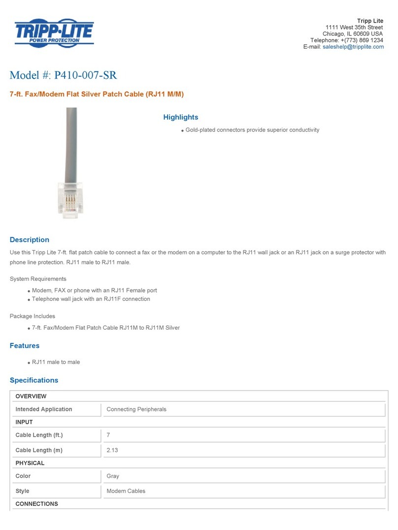
enphase Q-CONN-3P-10F User manual

QUICK INSTALL GUIDE (Models Q-CONN-3P-10F and Q-CONN-3P-10M)
Install the three-phase
IQ Field Wireable Connectors
© 2023 Enphase Energy. All rights reserved. Enphase, the e and CC logos, IQ, and certain other marks listed at
https://enphase.com/trademark-usage-guidelines are trademarks of Enphase Energy, Inc. in the US and other
countries. Data subject to change. Rev03/06-18-2023
PREPARATION
Check that you have IQ Field Wireable Connectors for three-phase IQ Cable as
needed for your installation. Both female and male connectors are sold in packs of
ten:
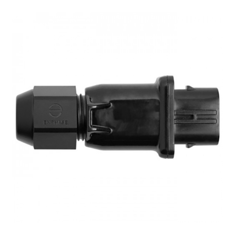
• IQ Field Wireable Connector for three-phase (female):
(Q-CONN-3P-10F)
• IQ Field Wireable Connector for three-phase (male):
(Q-CONN-3P-10M)
Make sure you have the following recommended tools:
• Screwdriver blade width 3.5 mm, PH1 screwdriver
• 30 mm wrench
Use IQ Field Wireable Connectors with three-phase IQ Cable or eld cable to:
• Easily connect three-phase IQ Cables without complex wiring
• Use a mated pair of connectors to end-feed the branch circuit with an AC connection
• Use mated pairs of connectors to connect with a remote part of the array
FEMALE CONNECTOR PARTS
MALE CONNECTOR PARTS
PARTS
*WARNING: Risk of equipment failure. Do not mix
male and female connector parts when assem-
bling connectors.
Technical data
Degree of protection IP66/IP68 (2m, 24h)
Nominal current
(Observe derating, see
graph below)
Conductor cross-section IEC/EN61984
6 mm235 A
4 mm232 A
2.5 mm224 A
Nominal voltage 690 V
Rated surge voltage 6 kV
Pollution degree 3
Operating temperature -40°C to 110°C
Material PPE
1. Cable gland
2. Seal
3. Housing
4. Contact carriers
1. Cable gland
2. Seal
3. Housing
4. Contact carriers
1
2
3
4
N
3
4
3
2
1
IEC/EN61984
Enphase Customer Support: https://enphase.com/contact/support

B) Connect the conductors to the contact carrier according to the
labels on the contact carrier.
* WARNING: Ensure that the correct connection for Line, Neutral,
Earth match according to the label on the contact carrier. In case
of mismatch, phase balance of system will be affected.
NOTE: For exible wires, we recommend using ferrules account to
DIN 46228 that are crimped with jointing clamp.
C) Torque the contact carrier screws to 1 N m.
D) Push the contact carrier into the housing until it snaps in audibly.
E) Tighten the cable gland to a torque of 4.5 N m.
* WARNING: Observe the permitted bending radius during installation.
The degree of protection might fail if the bend radius is exceeded.
A) Prepare the cable:
• Push the cable gland over the cable.
• If there are multiple seals, select a seal that ts your cable
diameter.
• Push the housing with a seal over the cable.
• Strip 50 mm of the outer jacket.
• Shorten conductors N, L1, L2, and L3 by 8 mm, but keep PE
(protection earth) at 50 mm.
• Strip 12 mm of the conductor insulation.
ASSEMBLY
Follow the steps to assemble IQ Field Wireable Connectors for three-phase connections.
FEMALE MALE
Loosening the cable
• Loosen the cable gland.
• Use the screwdriver to release the contact carrier on both sides.
• Pull the contact carrier from the housing.
• Loosen the screws on the contact carrier and loosen the wires.
B
AB
A
B
B
30
4.5 N m
rmin 4 xd
d
4.5 N m
30
CLICK !
CLICK !
N
3
Click
Click
1 N m
N
3
1 N m
N
3
8
12
50
8
12
50

- IQ FIELD WIREABLE CONNECTORS - THREE-PHASE
Safety Symbols
+DANGER: This indicates a hazardous situation, which if
not avoided, will result in death or serious injury.
*WARNING: This indicates a situation where failure to
follow instructions may be a safety hazard or cause
equipment malfunction. Use extreme caution and follow
instructions carefully.
;WARNING: Risk of burn. Failure to follow instructions may
result in burn injury.
✓NOTE: This indicates information particularly important
for optimal system operation.
SAFETY
IMPORTANT SAFETY INSTRUCTIONS.
SAVE THIS INFORMATION.
Follow all safety and assembly instructions when installing IQ
Field Wireable Connectors.
Safety Instructions
+DANGER: Risk of electric shock. Risk of re. Ensure that all
AC and DC wiring is correct and that none of the AC wires
are pinched, shorted, or damaged.
+DANGER: Risk of electric shock. Risk of re. Do not at-
tempt to repair or alter the IQ Field Wireable Connector.
+DANGER: Risk of electric shock. Risk of re. Make sure the
conductors are not damaged. If the exposed wires are
damaged, the system may not function properly.
*WARNING: Risk of equipment damage. Enphase male and
female connectors must only be mated with the matching
male/female connector.
*WARNING: Risk of equipment damage. This product is
intended for operation with a maximum operating temper-
ature of 110ºC.
*WARNING: When installing the cabling, secure any loose
cable to minimize tripping hazard.
*WARNING: Before installing or using the IQ Field Wireable
Connector, read all instructions and cautionary markings
in the technical description, on the Enphase System, and
on the photovoltaic (PV) equipment.
*WARNING: Never plug in or disconnect the connectors
under load. The connectors are not suitable for interrupt-
ing the current.
*WARNING: Without earthing connection.
✓NOTE: Maintenance and cleaning must be performed by
qualied personnel.
✓NOTE: Using unapproved attachments or accessories
may result in damage or injury.
✓NOTE: When looping the IQ Cable, do not form loops small-
er than 12 cm in diameter.
✓NOTE: Perform all electrical installations in accordance
with all applicable local electrical codes.
✓NOTE: To ensure optimal reliability and to meet warranty
requirements, install the IQ Field Wireable Connectors
according to the instructions in this guide.
✓NOTE: Protection against lightning and resulting voltage
surge must be in accordance with local standards.
✓NOTE: The connector is considered to be in compliance
only when assembled in the manner specied by these
assembly instructions.
✓NOTE: For exible wires, we recommend using ferrules ac-
count to DIN 46228 that are crimped with jointing clamp.
✓NOTE: Cable used with IQ Field Wireable Connectors must
meet the following requirements:
• Min/max outer insulation diameter (including the
clear second insulator): 8 mm/21 mm
• Wire size: 2.5 mm2to 6 mm2
DISCONNECT (if needed)
To disconnect three-phase IQ Field Wireable Connectors, release the
two connectors by pressing down the snap with a screwdriver. You can
then separate the connectors.
* WARNING: Never plug in or disconnect the connectors under
load. The connectors are not suitable for interrupting the current.
Enphase article number Enphase product SKU Type designation
150-00094 Q-CONN-3P-10F PRC 5-FC-FS6
150-00093 Q-CONN-3P-10M PRC 5-FC-MS6
Safety Instructions
+DANGER: Risk of electric shock. Do not use Enphase
equipment in a manner not specied by the manufacturer.
Doing so may cause death or injury to persons, or dam-
age to equipment.
+DANGER: Risk of electric shock. Be aware that installation
of this equipment includes risk of electric shock. Do not
use without rst removing AC power from the Enphase
System. Disconnect the power coming from the photovol-
taics before servicing or installing.
+DANGER: Risk of electric shock. Risk of re. Before mak-
ing any connections, verify that the circuit breakers are in
the off position. Double check all wiring before applying
power.
+DANGER: Risk of electric shock. Risk of re. Only use
electrical system components approved for wet locations,
including but not limited to conduit ttings.
+DANGER: Risk of electric shock. Risk of re. Only qualied
personnel should install, troubleshoot, or replace the IQ
Field Wireable Connector.
+DANGER: Risk of electric shock. Improper use of the IQ
Field Wireable Connector or its components may result in
a shock, re or explosion. To reduce these risks, discon-
nect all wiring before attempting any maintenance.
Note for third-party products:
Any third-party manufacturer or importer product(s) used to install or commis-
sion Enphase product(s) shall comply with the applicable EU Directive(s) and
requirements in the EEA (European Economic Area). It is the responsibility of
the installer to conrm that all such products are labelled correctly and have the
required compliant supporting documentation.
Compliance with EU Directives
This product complies with the following EU Directives and can be used in the
European Union without any restrictions.
• Low voltage directive (LVD) 2014/35/EU
• Restriction of hazardous substances (RoHS) 2011/65/EU
The full text of the EU declaration of conformity (DoC) is available at the
following internet address https://enphase.com/en-gb/installers/resources/
documentation.
Manufacturer:
Enphase Energy Inc.,
47281 Bayside Pkwy, Fremont, CA, 94538,
The United States of America, PH: +1 (707) 763-4784.
Importer:
Enphase Energy NL B.V.,
Het Zuiderkruis 65, 5215MV, ‘s-Hertogenbosch,
The Netherlands, PH: +31 73 3035859.

Revision history
REVISION DATE DESCRIPTION
140-00147-03 June 2023 Updated the document for product names and editorial changes.
© 2023 Enphase Energy. All rights reserved. Enphase, the e and CC logos, IQ, and certain other marks listed at
https://enphase.com/trademark-usage-guidelines are trademarks of Enphase Energy, Inc. in the US and other
countries. Data subject to change. Rev03/06-18-2023
This manual suits for next models
3
Other enphase Cables And Connectors manuals
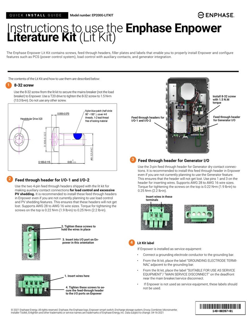
enphase
enphase EP200G-LITKIT User manual

enphase
enphase Engage Cable User manual
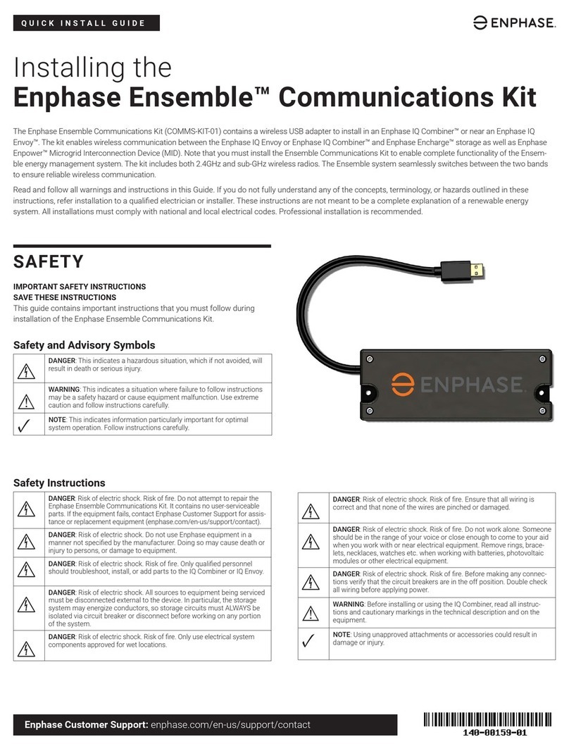
enphase
enphase Ensemble COMMS-KIT-01 User manual
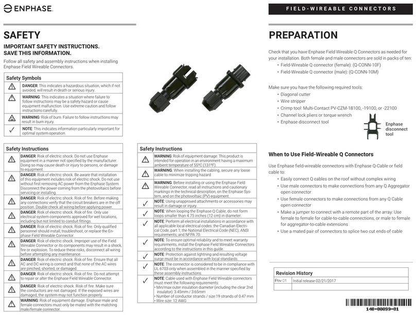
enphase
enphase Q Series User manual
enphase
enphase CT-200-SOLID User manual
enphase
enphase ET17-240-40 User manual
enphase
enphase IQ Series User manual
enphase
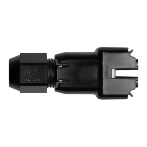
enphase Q-CONN-3P-10F User manual
enphase
enphase QD-CONN-10F User manual
