enphase EP200G-LITKIT User manual

Feed through header for Generator I/O
Use the 3-pin feed through header for Generator dry contact connec-
tions. It is recommended to install this feed through header in Enpower
even if you are not currently planning to use the Generator feature.
This ensures that the header will not get lost. Use pins 1 and 3 on the
header for inserting wires. Supports AWG 28 to AWG 16 wire sizes.
Torque for tightening the screws on the top is 0.22 N•m (1.9 lb•in) to
0.25 N•m (2.2 lb•in).
2. Tighten these screws to
hold the wires in place
3. Insert into I/O port on En-
power in this orientation
Insert wires in these
terminals
The Enphase Enpower Lit Kit contains screws, feed through headers, filler plates and labels that enable you to properly install Enpower and configure
features such as PCS (power control system), load control with auxiliary contacts, and generator integration.
QUICK INSTALL GUIDE Model number: EP200G-LITKIT
Instructions to use the Enphase Enpower
Literature Kit (Lit Kit)
The contents of the Lit Kit and how to use them are described below:
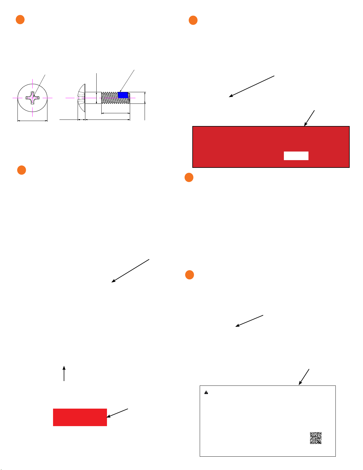
8-32 screw
Use the 8-32 screw from the lit kit to secure the mains breaker (not the load
breaker) to Enpower. Use a T20 drive to tighten the 8-32 screw to 1.5 N•m
(13.3 lb•in). Do not use any other screw.
Install 8-32 screw
with 1.5 N.M
torque
Feed through header for I/O-1 and I/O-2
Use the two 4-pin feed through headers shipped with the lit kit for
making auxiliary contact connections for load control and excessive
PV shedding. It is recommended to install these feed through headers
in Enpower even if you are not currently planning to use load control
and PV shedding features. This ensures that these headers will not get
lost. Supports AWG 28 to AWG 16 wire sizes. Torque for tightening the
screws on the top is 0.22 N•m (1.9 lb•in) to 0.25 N•m (2.2 lb•in).
Lit Kit label
If Enpower is installed as service equipment:
• Connect a grounding electrode conductor to the grounding bar.
• From the lit kit, place the label “GROUNDING ELECTRODE TERMI-
NAL” adjacent to the grounding bar.
• From the lit kit, place the label “SUITABLE FOR USE AS SERVICE
EQUIPMENT”/ “MAIN SERVICE DISCONNECT” on the deadfront
near the main breaker/service disconnect.
• If Enpower is not used as service equipment, these labels should
not be used.
© 2021 Enphase Energy. All rights reserved. Enphase, the Enphase logo, Enpower smart switch, Encharge storage system, Envoy, Combiner, Microinverter,
Installer Toolkit, Enlighten and other trademarks or service names are trademarks of Enphase Energy, Inc. Data subject to change. 04-16-2021
rev. Modificaton ECN Date Drawing Approved
Material
Hardness
Finish
Description
Stainless steel A2-70 Customer Code
Customer P/N
& drawing no.
Drawing No.
Article No.
Scale
Size
UNSPECIFIED TOLERANCES
Version
QP Level Q2
02
All dimensions are in inch
Third angle projection
00 Created N/A
2019/12/4
Mary He Don Tang
A4
Not ot Scale
6358144
Business Unit
BOC
Important Disclaimer
The technical recommendations contained in this publication are necessarily of a general nature and should not be relied on for specific applications without first
securing competent advice. Whilst Bossard has taken all reasonable steps to ensure the information contained herein is accurate and current, Bossard does not
warrant the accuracy or completeness of the information and does not accept liability for errors or omissions.
Hexalobular socket pan head machine
screw #8-32UNCX0.63
0.306-0.322
0.105-0.115 0.63
0
-0.03
#8-32UNC
Hexalobular Drive X20
Note:
1.Without burr,Sharp edges or other disfigurements.
2.The part is RoHS compliance.
3. Refer ASME B18.6.3.
4. Comply with thread locking standard IFI 124.
Passivation
02
Q2
Mary He
Mary He
2019/12/9
6358144
0.055-0.070
01 Add nylon patch. N/A
2019/12/5
Mary He Don Tang
Nylon blue patch (half circle
90° ~180° ), cover 4-6
threads, 1-2 lead thread
free of locking material
02
Change nylon patch standard to IFI 124 for inch screw, was IFI 524.
N/A
2019/12/9
Mary He Don Tang
730-00305
1. Insert wires here
4. Tighten these screws to se-
cure the feed-through header
to the I/O ports on Enpower
Feed through headers for
I/O-1 and I/O-2
Feed through header
for Generator I/O
2
3
4
1
CT Label
For Production as well as Consumption/PCS CTs, you must apply
the following label to each CT when the system is congured to use
PCS-based current limiting.
The available space on the CTs for labeling is as follows
Consumption/PCS CT (CT-200-SPLIT):
• Left side: 20mm(vertical) x 14mm (Horizontal)
• Back side: 20mm (vertical) x 20mm (Horizontal)
Production CT (CT-200-SOLID):
• 9mm(vertical) x 30mm(horizontal)
THE MAXIMUM CURRENT BACKFED BY THIS SYSTEM TO THE MAIN
PANEL MAY BE CONTROLLED ELECTRONICALLY. REFER TO MANU-
FACTURER’S INSTRUCTIONS FOR MORE INFORMATION
PCS CONTROLLED CURRENT SETTING: ___________ AMPS
Manual Override Label
This is to be applied to be above (north of) the manual override switch
on the Enpower deadfront.
M6screwsandllerplates
During Enpower installation, after sliding in Enpower on the wall-
mount bracket shelf, remove the lift handles and on the bottom
handle mounts, use the two provided partial-threaded custom M6
screws to secure each side of the Enpower and tighten to 0.5 N•m
(4.4 lb•in) or less. The threaded portion of the screw engages with the
bracket, while the unthreaded portion of the screw engages with the
hole in the bracket to prevent vertical movement of the bracket.
* WARNING! Risk of injury and equipment damage. Do not skip this
step. Without these screws in place, the Enpower may fall and cause
injury or damage if bumped or shaken.
Use the four ller plates, provided in the lit kit, to cover the screws.
rev. Modificaton ECN Date Drawing Approved
Material
Hardness
Finish
Description
Phillips truss head machine screw
M6x25
Passivation
Stainless steel 304, A2-70 Customer Code
Customer P/N
& drawing no.
Drawing No.
Article No.
Scale
Size
UNSPECIFIED TOLERANCES
Version
QP Level Q2 00
All dimensions are in mm
Third angle projection
00 Created 13-Nov-19 Mary He Don Tang
A4
Not ot Scale
6355781
Business Unit
BOC
Important Disclaimer
The technical recommendations contained in this publication are necessarily of a general nature and should not be relied on for specific applications without first
securing competent advice. Whilst Bossard has taken all reasonable steps to ensure the information contained herein is accurate and current, Bossard does not
warrant the accuracy or completeness of the information and does not accept liability for errors or omissions.
Note:
1. Without burr, sharp edges or other disfigurements.
2. The part is RoHS compliance.
3. Comply with thread locking standard IFI 524.
00
Q2
Mary He
Mary He
2019/11/13
6355781
M6xP1.0
Ø6
0
-0.18
13.87-14.55 3.38-3.81
Phillips Drive #3
Nylon blue patch (half circle
90° ~180° ), cover 4-6
threads, 1-2 lead thread
free of locking material
25±0.42
20Ref
730-00296
01 INITIAL RELEASE - ECO-005109 MN
17 FEB 21
M. Nagy 17 FEB 21
780-00568
1 1
Label, Enpower, CT, Field
01
D
C
B
A
B
A
1
3
45
678
12
34
56
78
1420 N. McDowell Blvd.
PETALUMA, CA 94954
(707) 763-4784
The information contained in this document is the
proprietary and confidential information of ENPHASE
ENERGY, Inc.. You will not provide, make available
or disclose (or use for any purpose other than that
contemplated by this document) any such information
to any other party without the express, written consent
of ENPHASE ENERGY, Inc.
D
C
SIZE
SHEET OF
REV
DRAWING NO.
2
DWN BY
ENGR
MFG TITLE
THIRD ANGLE PROJECTION
3D MODEL
REVISIONS
REV DESCRIPTION CHKD DATE
APPROVALS DATE
B
DO NOT SCALE THIS DRAWING
Scale: 2:1
25.00
8.00
This sensor is part of a
Power Control System.
Do not remove or disable.
Replace with the same type and rating.
7. LABEL MUST BE UL RECOGNIZED (PGDQ2) AND CSA
ACCEPTED AS SUITABLE FOR OUTDOOR USE AT
TEMPERATURES FROM -40°C TO +65°C AND SUITABLE
FOR THE SURFACE TO BE APPLIED (PER UL RECOGNIZED
COMPONENT DIRECTORY). EACH LABEL MUST BE MARKED
WITH VENDOR’S MARK AS DEFINED IN THE CSA LIST OF
ACCEPTED ADHESIVE-TYPE NAMEPLATES. THE SMALLEST
SHIPPING PACKAGE MUST BE MARKED WITH SUPPLIER’S
NAME AND UL DESIGNATION.
1. MATERIAL: 3M 7871 POLYESTER, 3M 350 ADHESIVE
WITH CLEAR OVERLAY ON FRONT.
2. USE UV RESISTANT INK.
3. DIE CUT LABEL AND SHIP IN SHEETS OR ON ROLL.
4. ARTWORK SUPPLIED IN ILLUSTRATOR FORMAT.
5. COLORS: BACKGROUND RED (RGB: 255, 0, 0) TEXT WHITE
6.VENDOR HAS THE AUTHORITY TO MODIFY COLORS
SLIGHTLY TO SUIT AVAILABLE INKS.
Auxiliary Contact Labels
This label can be applied on top of the existing label for the lugs in
Enpower.
Stick Manual Override
label here
01 INITIAL RELEASE - ECO-005109 MN
26 FEB 21
M. Nagy
18 FEB 21
780-00669
1 1
Label, Enpower R1, MOR
01
D
C
B
A
B
A
1
3
45
678
12
34
56
78
1420 N. McDowell Blvd.
PETALUMA, CA 94954
(707) 763-4784
The information contained in this document is the
proprietary and confidential information of ENPHASE
ENERGY, Inc.. You will not provide, make available
or disclose (or use for any purpose other than that
contemplated by this document) any such information
to any other party without the express, written consent
of ENPHASE ENERGY, Inc.
D
C
SIZE
SHEET OF
REV
DRAWING NO.
2
DWN BY
ENGR
MFG TITLE
THIRD ANGLE PROJECTION
3D MODEL
REVISIONS
REV DESCRIPTION CHKD DATE
APPROVALS DATE
B
DO NOT SCALE THIS DRAWING
Scale: Full
200.00
Manual Override Instructions:
Contact Enphase customer support at (877) 797-4743 and confirm before following instructions below.
Steps for Initiating Manual Override (Tied to Grid)
1. OPEN the breakers for Encharge, Mains, and Auto Transformer in Enpower (The mains breaker could be located inside the main service panel).
Note: No need to open PV combiner and load side breaker inside Enpower.
2. Turn OFF all Encharge units by turning OFF the DC switches on each Encharge base unit.
3. Disable the generator. Turn off generator output breaker inside the generator. Ensure your generator is turned off.
4. Wait for 2 minutes.
5. Remove the sticker from the manual override section of the Enpower. Use a Philips head screwdriver to remove the screw on the plastic cover.
Then remove the plastic cover to make the small manual override toggle visible.
6. Turn the toggle to the left to manually CLOSE the MID relay.
7. CLOSE the mains breaker.
The Enpower system is now in manual override mode and grid tied.
Steps for Exiting Manual Override:
1. OPEN the breakers for Encharge, Mains, and Auto Transformer in Enpower.
2. Turn OFF all Encharge units by turning OFF their DC switches.
3. Wait for 2 minutes.
4. Turn the manual override toggle to the right to manually OPEN the MID relay.
5. CLOSE all the breakers in sequence:
a. NFT breaker inside Enpower
b. Mains breaker (In Enpower or main panel)
c. Encharge breaker inside Enpower
6. Turn ON all Encharge units by turning ON their DC switches.
The Enpower system is now no longer in manual override mode and is fully fuctional.
7. LABEL MUST BE UL RECOGNIZED (PGDQ2) AND CSA
ACCEPTED AS SUITABLE FOR OUTDOOR USE AT
TEMPERATURES FROM -40°C TO +65°C AND SUITABLE
FOR THE SURFACE TO BE APPLIED (PER UL RECOGNIZED
COMPONENT DIRECTORY). EACH LABEL MUST BE MARKED
WITH VENDOR’S MARK AS DEFINED IN THE CSA LIST OF
ACCEPTED ADHESIVE-TYPE NAMEPLATES. THE SMALLEST
SHIPPING PACKAGE MUST BE MARKED WITH SUPPLIER’S
NAME AND UL DESIGNATION.
1. MATERIAL: 3M 7871 POLYESTER, 3M 350 ADHESIVE
WITH CLEAR OVERLAY ON FRONT.
2. USE UV RESISTANT INK.
3. DIE CUT LABEL AND SHIP IN SHEETS OR ON ROLL.
4. ARTWORK SUPPLIED IN ILLUSTRATOR FORMAT.
5. COLORS: BACKGROUND WHITE, BLACK C
6.VENDOR HAS THE AUTHORITY TO MODIFY COLORS
SLIGHTLY TO SUIT AVAILABLE INKS.
100.00
Scan QR code to view
instruction videos
Label Sample
Label Sample
Stick PCS label here
PCS Label
Apply the PCS label on the deadfront. Record the maximum operating
amps value on the label. This value indicates the maximum current
57
8
9
6
Stick CT label
for PCS here
Stick CT label
for PCS here
Label Sample

Enphase Customer Support: enphase.com/en-us/support/contact
Safety and Advisory Symbols
+DANGER: This indicates a hazardous situation, which if not avoided, will
result in death or serious injury.
*WARNING: This indicates a situation where failure to follow instructions
may be a safety hazard or cause equipment malfunction. Use extreme
caution and follow instructions carefully.
✓NOTE: This indicates information particularly important for optimal system
operation. Follow instructions carefully.
Safety Instructions
+DANGER: Risk of electric shock. Risk of re. Only qualied electricians should
install, troubleshoot, or replace the Enpower.
+DANGER: Risk of electric shock. Risk of re. Do not attempt to repair the
Enpower. Tampering with or opening the Enpower will void the warranty.
If the Enpower fails, contact Enphase Customer Support for assistance at
enphase.com/en-us/support/contact.
+DANGER: Risk of electric shock. Do not use Enphase equipment in a manner
not specied by the manufacturer. Doing so may cause death or injury to
persons, or damage to equipment.
+DANGER: Risk of electric shock. Do not install the Enpower without rst
removing AC power from the photovoltaic system and ensuring that the DC
switch on the Enphase Encharge batteries are off. Disconnect the power
coming from the photovoltaics and ensure that the DC switch on the En-
charge batteries are off before servicing or installing.
+DANGER: Risk of electric shock. Risk of re. Do not work alone. Someone
should be in the range of your voice or close enough to come to your aid
when you work with or near electrical equipment.
+DANGER: Risk of re. Do not allow or place ammable, sparking, or explosive
items near the Enpower.
+DANGER: Risk of electric shock. In areas where ooding is possible, install
the Enpower at a height that prevents water ingress.
*WARNING: Risk of equipment damage. Enpower is shipped and stored on its
back. The upright position is only needed when installed.
*WARNING: You must install the Enpower only on a suitable wall using an
Enphase wall-mount bracket.
*WARNING: Before installing or using the Enpower, read all instructions and
cautionary markings in this guide and on the equipment.
*WARNING: Do not install or use the Enpower if it has been damaged in any
way.
*WARNING: Do not sit on, step on, place objects on, or insert objects into the
Enpower.
*WARNING: Do not place beverages or liquid containers on top of the
Enpower. Do not expose the Enpower to ooding.
✓NOTE: Perform installation and wiring, including protection against lightning
and resulting voltage surge, in accordance with all applicable local electrical
codes and standards.
✓NOTE: Because Encharge is grid forming, you must install signage in accord-
ance with NEC articles 705, 706, and 710.
✓NOTE: Using unapproved attachments or accessories could result in dam-
age or injury.
✓NOTE: Install properly rated over current protection as part of the system
installation.
✓NOTE: To ensure optimal reliability and to meet warranty requirements, the
Enpower must be installed and/or stored according to the instructions in this
guide.
✓NOTE: The Enpower is compatible only with the IQ Envoy or Envoy
S-metered communications gateway properly tted with USB hub, USB
radios, and production and Consumption/PCS CTs. The Envoy is required
for operation of the Enpower. Earlier versions of the Enphase Envoy commu-
nications gateway are incompatible.
✓NOTE: The Enphase Enpower is intended to operate with an Internet connec-
tion through the Envoy. Failure to maintain an Internet connection may have
an impact on the warranty. See Limited Warranty for full terms and services
(enphase.com/warranty).
✓NOTE: When replacing an Enphase Enpower, you must replace it with an
Enpower of the same type, with the same AC current rating.
✓NOTE: Properly mount the Enpower. Ensure that the mounting location is
structurally suited to bearing the weight of the Enpower.
✓NOTE: During use, storage, and transport, keep the Enpower:
• Properly ventilated
• Away from water, other liquids, heat, sparks, and direct sunlight
• Away from excessive dust, corrosive and explosive gases, and oil smoke
• Away from direct exposure to gas exhaust, such as from motor vehicles
• Away from falling or moving objects, including motor vehicles. If mounted
in the path of a motor vehicle, we recommend a 91cm (36-inch)
minimum mounting height
• In a location compliant with re safety regulations
• In a location compliant with local building codes and standards
1NOTE: While Enpower provides capability for connection of a generator, it
does not presently support use with generators. Do not attempt to connect a
generator until Enpower is ready to support a generator. This functionality is
reserved for future use and will require an upgrade process to be followed by
a qualied electrician.
2NOTE: Enpower is not suitable for use as service equipment in Canada.
SAFETY
IMPORTANT SAFETY INSTRUCTIONS. SAVE THESE INSTRUCTIONS. This guide contains important instructions that you must follow during installation
and maintenance of the Enphase Enpower. Failing to follow any of these instructions may void the warranty (enphase.com/warranty).
In Case of Fire or Other Emergency
In all cases:
• If safe to do so, switch off the AC breaker for the Enpower circuit, and if an
isolator switch is present, switch off the AC isolator for the Enpower circuit.
• Contact the re department or other required emergency response team.
• Evacuate the area.
In case of re:
• When safe, use a re extinguisher. Suitable types are A, B, and C dry chemical
re extinguishers. Additional extinguishing media include carbon dioxide, or
alcohol-resistant foams.
In case of ooding:
• Stay out of water if any part of the Enpower or wiring is submerged.
• If possible, protect the system by nding and stopping the source of the
water, and pumping it away.
• If water has contacted the UNIT, call your installer to arrange a inspection.
If you are sure that water has never contacted the battery, let the area dry
completely before use.
In case of unusual noise, smell or smoke:
• Ensure nothing is in contact with the Enpower or in the venting area on top of
the Enpower.
• Ventilate the room.
• Contact Enphase Customer Support at enphase.com/en-us/support/contact.
Safety Instructions, continued
Environmental Protection
ELECTRONIC DEVICE: DO NOT THROW AWAY. Waste elec-
trical products should not be disposed of with household
waste. Refer to your local codes for disposal requirements.
Other enphase Cables And Connectors manuals

enphase
enphase CT-200-SOLID User manual

enphase
enphase Ensemble COMMS-KIT-01 User manual

enphase
enphase QD-CONN-10F User manual

enphase
enphase Q-CONN-3P-10F User manual

enphase
enphase Q-CONN-3P-10F User manual

enphase
enphase IQ Series User manual

enphase
enphase Engage Cable User manual

enphase
enphase ET17-240-40 User manual

enphase
enphase Q Series User manual
Popular Cables And Connectors manuals by other brands


Nordost
Nordost NORSE 2 instruction manual

Tyco Electronics
Tyco Electronics AMP 1804018-1 Installation sheet

Siemens
Siemens 3VA1 100 630A Series operating instructions

PCB Piezotronics
PCB Piezotronics IMI SENSORS 009M205/100 Installation and operating manual

IOGear
IOGear GHSP8422 quick start guide

Griven
Griven AL4750 instruction manual


