enphase Q RELAY Operator's manual

Q RELAY (multiphase) INSTALLATION
PREPARATION
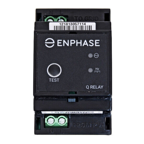
In Enphase installations, the multiphase Q Relay (network system
relay controller) acts as a galvanic disconnection device. It is designed
for three-phase or multiphase use and has built in contactors. During
specied grid abnormalities, the Q Relay disconnects the Enphase
Microinverters from the AC grid, and when the voltages return to normal
and the grid frequency is in the acceptable range, the Q Relay reconnects
the microinverters to the AC grid. The Q Relay has built in current sensing
that can detect DC current injection required by CEI 0-21 requirements.
The Q Relay works together with the Envoy-S to meet the need to break
lines and neutral per grid requirements.
See full installation instructions for the Enphase Envoy-S and/or En-
phase Microinverters at: enphase.com/support.
It is best practice to install the Q Relay when installing the Envoy-S and
before commissioning the system.
The Q relay is IP-20 rated and supports 25A per phase.
You must mount it in an environmentally protected enclosure. Typically
this is a switchboard.
You must also use 2.5 - 6.0 mm² conductors for relay connections.
© 2021 Enphase Energy. All rights reserved. Enphase, the Enphase logo, Enpower smart switch, Encharge storage system, IQ Envoy, IQ combiner,
IQ microinverter, Installer Toolkit, Enlighten and other trademarks or service names are the trademarks of Enphase Energy, Inc. Data subject to
change. 2021-05-31
INSTALLATION
+DANGER: Risk of electric shock. Always open or disconnect
circuit from power-distribution system (or service) of building
and PV side before installing or servicing the Q Relay.
A ) Install the Enphase Envoy-S as directed in the Envoy-S Quick Install
Guide.
B ) Install the Q Relay in a protected environment (e.g., switchboard)
on a 35 mm DIN rail near the Envoy-S.
+DANGER: Risk of electric shock. The Q Relay is intended for
installation in an electrical enclosure (i.e. switchgear) that
prevents Operator access to hazardous live parts.
C ) Connect the Line and Neutral conductors (2.5 - 6.0 mm² ) from
the PV system to the “FROM PV” terminals of the Q Relay so that
the Neutral is on the N terminal and the Lines connect to the L1,
L2, and L3 terminals.
D ) Connect a Neutral conductor (2.5 - 6.0 mm² ) from the “TO GRID”
N terminal of the Q Relay to the Neutral busbar.
PROGRAM FOR 1 or 2 PHASE
OPERATION
The 3-phase Q-Relay can also support 2-phase and single-phase
applications. To program the number of phases:
A ) Press and hold the test button. The phase voltage indicators (V1,
V2, V3), will turn red and the relay will click. After approx. 6 sec-
onds the phase voltage LEDs will start ashing red. The number
of red LEDs ashing corresponds to the number of phases. A
sequence of 3, then 2, then 1 ashing LEDs is repeated.
B ) Release the test button when the appropriate number of LEDs
are ashing.
NOTE:
• The selected mode will persist through power cycling.
• The selected number of phases must be connected in sequence
starting at L1.
• All options must include a Neutral.
• In some installations the Q-Relay may trip due to DCI during
commissioning while it is learning the system size. This may
occur when commissioning on cloudy days and is considered
normal operation.
AUTO TEST
Section A.4.4 of CEI 0-21 : 2019 requires an Autotest to be performed.
This can be initiated by pressing the test button on the Q-Relay for
less than 2 seconds. The results of the test will then be available
via the Enlighten platform for homeowners and installers within 30
minutes of the test being completed. During the test the LEDs can be
observed to cycle Red, and if the test passes, the Q-Relay device will
re-enter service. If the test fails, the Frequency/DCI LED will ash Red
continuously.
NOTE: The unit should have been properly powered up and congured
for greater than 10 minutes before starting the test.
Over voltage category (EN 61010-1) III
CAT III GRID terminal is rated for
measurement category III
Pollution degree (EN 61010-1) 2
Supply range 85 to 265 VAC
Nominal input frequency 50 Hz
Voltage and frequency acquisition
time on valid input during normal
operation
100 ms (5 line cycles @ 50Hz)
Output 4-pole normally open relay (L1, L2,
L3 & N)
Output power rating 6 kVA per phase
Output rating (typical) 240 VAC, 25A
Power consumption 18 VA
Conducted and radiated EMI IEC 61326, BS EN 50065-1 & 2-2, BS
EN 61326-1&2, BS EN 61000-3-11&12
Operating temperature range -40 °C to 50 °C
Altitude rating 2000m
IP rating IP 20 (must be in protected
environment)
Relative humidity 0 to 95 non-condensing
SPECIFICATIONS
E ) Connect the Line conductors (2.5 - 6.0 mm²) from the “TO GRID”
L terminal of the Q Relay to an EN/IEC/AS/NZS 60947-2 approved
circuit breaker, rated for no more than 20A.
* WARNING: The circuit breaker must be suitably located and
easily reached. It must also be marked as the disconnecting
device for the PV system.
F ) Tighten all relay terminal connections to 0.85 N m.
G ) Energise the circuit.
H ) Upon power up, the LEDs should all turn green to indicate the AC
voltage and frequency are within specication of the grid code.
See the LED states table.
I ) Use the Enphase Installer Toolkit to apply a grid prole to the Q
Relay and microinverters. Do not skip this step.

Q-RELAY-2-3P-ITA WIRING DIAGRAM
FROM
SOLAR
INVERTERS
N L1 L2 L3
N L1 L2 L3
L1
L2
L3
N
I1
I2
I3
ENVOY-S
N
L1
L2
L3
N
L1
L2
L3
TO AC
GRID
Q-RELAY-2-3P-ITA
PHASE
COUPLER
PRODUCTION
CTs
TO
STORAGE
(OPTIONAL)
TO
ADDITIONAL
Q-RELAYs
(IF REQUIRED)
DC I
SENSE
LED #1
(Voltage,
V1-N)
LED #2
(Voltage,
V2-N)
LED #3
(Voltage,
V3-N)
LED #4
(Hz, DCI(Di-
rect Current
Injection))
Description Condition Relay
OFF OFF OFF OFF Description/Status Unpowered or
non-functional
OPEN
GREEN
(solid)
X X X Phase voltage (V1-N) is within range. -- --
X GREEN
(solid)
X X Phase voltage (V2-N) is within range. -- --
X X GREEN
(solid)
X Phase voltage (V3-N) is within range. -- --
X X X GREEN
(solid)
Frequency and DCI (if applicable) are all within spec. -- --
GREEN
(solid
GREEN
(solid)
GREEN
(solid)
GREEN
(solid)
Voltage, frequency and DCI (if applicable) are all within spec. Normal CLOSED
RED (solid) X X X Phase voltage (V1-N) setpoints (HV1, HV2, LV1, LV2 or LV3)
has timed out or the reconnection value has not been met.
FAULT OPEN
X RED (solid) X X Phase voltage (V2-N) setpoints (HV1, HV2, LV1, LV2 or LV3)
has timed out or the reconnection value has not been met.
FAULT OPEN
X X RED (solid) X Phase voltage (V3-N) setpoints (HV1, HV2, LV1, LV2 or LV3)
has timed out or the reconnection value has not been met.
FAULT OPEN
X RED
(ashing)
X X Voltage detected on phase 2 (V2-N) but this phase is not
congured. Recongure phases.
ERROR Normal
operation
X X RED
(ashing)
X Voltage detected on phase 3 (V3-N) but this phase is not
congured. Recongure phases.
ERROR Normal
operation
X X X RED (solid) Grid frequency (V1) has timed out or reconnect frequency
hasn't been met yet or the DCI threshold is met (if used) and
the relay is opened.
FAULT OPEN
RED (solid) RED (solid) RED (solid) RED (solid) TEST button is being pushed. Test contactor and
autocong phase
assignments
Toggle state
RED/GREEN
(ashing)
RED/GREEN
(ashing)
RED/GREEN
(ashing)
RED
(ashing)
Corrupt FLASH FAULT OPEN
LED BEHAVIOR
Q-RELAY-2-3P-ITA WIRING DIAGRAM SAFETY
IMPORTANT SAFETY INSTRUCTIONS.
SAVE THIS INFORMATION.
Follow all safety and assembly instructions when installing the
Q Relay.
Safety Instructions
+DANGER: Risk of electric shock. Risk of re. Do not attempt to re-
pair the Q Relay; it contains no user-serviceable parts. Tampering
with or opening the Q Relay will void the warranty. Warranty void
if cover removed. If the Q Relay fails, contact Enphase Customer
Support for assistance (http://enphase.com/global/contact/).
+DANGER: Risk of electric shock. Always open or disconnect circuit
from power-distribution system (or service) of building and PV
side before installing or servicing the Q Relay.
+DANGER: Risk of electric shock. Do not use Enphase equipment in
a manner not specied by the manufacturer. Doing so may cause
death or injury to persons, or damage to equipment.
+DANGER: Risk of electric shock. Risk of re. Only qualied person-
nel should troubleshoot, install, or replace the Q Relay.
+DANGER: Risk of electric shock. The Q Relay is intended for in-
stallation in an electrical enclosure (i.e. switchgear) that prevents
Operator access to hazardous live parts.
*WARNING: Before installing or using the Q Relay, read all instruc-
tions and cautionary markings in the technical description and on
the Q Relay.
*WARNING: Risk of equipment damage. When installing the Q Re-
lay in an enclosure, choose an area for installation where ambient
temperature remains between -40º C and 50º C.
*WARNING: The temperature of the terminals may exceed 60º C.
Use an appropriately temperature-rated cable to connect to the
terminals.
*WARNING: The circuit breaker must be suitably located and easily
reached. It must also be marked as the disconnecting device for
the PV system.
✓NOTE: Perform all electrical installations in accordance with all
national and local electrical codes.
✓NOTE: Install a residual current circuit breaker if required by
national regulations.
✓NOTE: To ensure optimal reliability and to meet warranty require-
ments, the Enphase Q Relay must be installed according to the
instructions in this guide.
Enphase Customer Support: enphase.com/global/contact

INSTALLAZIONE DEL RELÈ Q (multifase)
PREPARAZIONE
Nelle installazioni Enphase, il Relè Q multifase (controller relè del sistema
di rete) agisce come un dispositivo di isolamento galvanico. Esso è
progettato per l'utilizzo in monofase e trifase e integra dei contattori. In
presenza di determinate anomalie di rete, il Relè Q scollega i Microin-
verter Enphase dalla rete CA e quando la tensione ritorna alla normalità
e la frequenza della rete raggiunge valori accettabili, il Relè Q provvede
a ricollegare i microinverter alla rete CA. Il Relè Q integra un sensore di
corrente in grado di rilevare la corrente CC iniettata in conformità con i
requisiti della norma CEI 0-21.
Il Relè Q opera insieme ad Envoy-S per soddisfare la necessità di inter-
rompere le linee e il neutro su richiesta della rete.
Vedere istruzioni complete per l'installazione di Enphase Envoy-S e/o dei
Microinverter Enphase all'indirizzo: http://enphase.com/global/contact/
È buona prassi installare il Relè Q quando si installa Envoy-S e prima di
mettere in servizio il sistema.
Il Relè Q è classicato IP-20 e supporta 25 A per fase.
Deve essere montato all’interno di un in ambiente protetto. Solitamente si
tratta di un quadro.
È inoltre necessario utilizzare conduttori da 2,5 - 6,0 mm² per i collega-
menti con il relè.
INSTALLAZIONE
+ PERICOLO! Rischio di scosse elettriche. Interrompere sempre
l'alimentazione ai circuiti prima di effettuare il cablaggio.
A ) Installare Enphase Envoy-S come descritto nella
https://enphase.com/it-it/support/envoy-guida-rapida-allinstallazione
B ) Installare il Relè Q in un ambiente protetto (ad es., un quadro) su
una guida DIN da 35 mm vicino a Envoy-S. Il Q Relay è previsto per
l’installazione in un armadio elettrico (ad es. Quadro elettrico) che
impedisce l’accesso dell’operatore a parti sotto tensione pericolose.
C ) Collegare i conduttori di Fase e il Neutro (2,5 - 6,0 mm²) dal sistema
fotovoltaico ai terminali “FROM PV” del Relè Q in modo che il Neutro
sia sul morsetto N e le Fasi siano collegate ai morsetti L1, L2 e L3.
+ PERICOLO: Rischio di scosse elettriche. Effettuare sempre le connes-
sioni ai terminali del fotovoltaico prima di completare le connessioni
ai terminali di rete. Se i terminali di rete vengono collegati per primi, i
terminali del fotovoltaico risulteranno sotto tensione.
D ) Collegare il conduttore del Neutro (2,5 - 6,0 mm²) dal terminale N “TO
GRID” del Relè Q alla barra di distribuzione del Neutro.
E ) Collegare i conduttori di Fase (2,5 - 6,0 mm²) dal terminale L “TO GRID” del
Relè Q ad un interruttore omologato EN/IEC/AS/NZS 60947-2, classicato
per non più di 20 A.
*AVVERTENZA: L'interruttore deve essere sistemato in posizione idonea e
facilmente raggiungibile. Esso deve essere contrassegnato come dispositivo
di isolamento per il sistema fotovoltaico.
F ) Serrare tutte le connessioni dei terminali del relè con una coppia di 0,85 Nm.
G ) Alimentare il circuito.
H ) Al momento dell'alimentazione, i LED devono illuminarsi in verde ad indicare
che la tensione CA e la frequenza rientrano dei valori prescritti dalle speci-
che della rete. Vedere la tabella degli stati dei LED.
I ) Utilizzare Enphase Installer Toolkit per applicare un prolo di rete al Relè Q e
ai microinverter. Non saltare questo passo.
Categoria di sovratensione (EN
61010-1)
III
CAT III I terminali di RETE sono omologati
per la categoria di misurazione III
Grado di inquinamento (EN 61010-1) 2
Tensione di alimentazione Da 85 a 265 V CA
Frequenza di ingresso nominale 50 Hz
Tempo di acquisizione di tensione
e frequenza su un ingresso valido
durante il normale funzionamento
100 ms (5 cicli di linea a 50 Hz)
Uscita Relè a 4 poli normalmente aperto
(L1, L2, L3 e N)
Potenza nominale di uscita 6 kVA per fase
Uscita nominale (tipica) 240 V CA, 25 A
Consumo energetico 18 VA
IEM condotte e irradiate IEC 61326, BS EN 50065-1 e 2-2,
BS EN 61326-1&2, BS EN 61000-
3-11e12
Gamma di temperature di esercizio Da -40°C a 50°C
Classicazione IP IP 20 (deve essere utilizzato in un
ambiente protetto)
Umidità relativa Da 0 a 95 in assenza di condensa
SPECIFICHE
PROGRAMMARE IL FUNZIONAMENTO MO-
NOFASE O BIFASE
Il Relè Q trifase può anche supportare le applicazioni mono e bifase. Per pro-
grammare il numero di fasi:
A ) Tenere premuto il pulsante di test. Gli indicatori della tensione di fase (V1,
V2, V3), diventano rossi e il relè scatta. Dopo circa 6 secondi, i LED della
tensione di fase iniziano a lampeggiare in rosso. Il numero di LED rossi che
lampeggiano corrisponde al numero di fasi. Viene ripetuta una sequenza di
3, poi 2 e poi 1 LED lampeggianti.
B ) Rilasciare il pulsante di test quando il numero appropriato di LED
lampeggia.
NOTA:
• la modalità selezionata permane per tutto il ciclo di alimentazione.
• Il numero selezionato di fasi deve essere connesso in sequenza a partire
da L1.
• Tutte le opzioni devono includere il Neutro.
• In alcuni impianti, il Relè Q può scattare a causa di una iniezione di corren-
te continua durante la messa in servizio mentre è in corso la fase di rico-
noscimento del sistema. Ciò può vericarsi quando la messa in servizio
avviene in giornate nuvolose ed è considerato un funzionamento normale.
© 2021 Enphase Energy. Tutti i diritti riservati. Enphase, il logo Enphase, l'interruttore intelligente Enpower, il sistema di accumulo Encharge, IQ Envoy, IQ
Combiner, IQ Microinverter, Installer Toolkit, Enlighten e altri marchi o nomi di servizi sono marchi di Enphase Energy, Inc.
Dati soggetti a modiche. 2021-05-31
AUTO TEST
Per impianti di potenza inferiore a 11,08 kW, la norma CEI 0-21 richiede l’effet-
tuazione di un Autotest. Questo può essere avviato premendo il pulsante di
test sul Relè Q per meno di 2 secondi. I risultati del test saranno quindi resi di-
sponibili sulla piattaforma Enlighten a proprietari di case e installatori entro 30
minuti dal completamento del test stesso. Durante il test i LED diventano rossi
e, se il test viene superato, il Relè Q potrà rientrare in servizio. Se il test fallisce,
il LED Frequenza/DCI (iniezione corrente continua) continuerà a lampeggiare
in rosso.
NOTA: l’unità deve essere stata correttamente alimentata e congurata per più
di 10 minuti prima dell’avvio del test.

LED #1
(Tensione,
V1-N)
LED #2
(Tensione,
V2-N)
LED #3
(Tensione,
V3-N)
LED #4
Hz,DCI-
(Iniezione
di corrente
continua)
Descrizione Condizione Relè
OFF OFF OFF (Hz, DCI) Descrizione/Stato Non alimentato o non
funzionante
APERTO
VERDE
(sso)
X X X La tensione di fase (V1-N) rientra nell’intervallo. -- --
X VERDE
(sso)
X X La tensione di fase (V2-N) rientra nell’intervallo. -- --
X X VERDE
(sso)
X La tensione di fase (V3-N) rientra nell’intervallo. -- --
X X X VERDE
(sso)
Frequenza e DCI (se applicabile) rientrano nei valori di specica -- --
VERDE
(sso)
VERDE
(sso)
VERDE
(sso)
VERDE
(sso)
Tensione, frequenza e DCI (se applicabile) rientrano nei valori di
specica
Normale CHIUSO
ROSSO
(sso)
X X X I punti di riferimento della tensione di fase (V1-N) (HV1, HV2, LV1,
LV2 o LV3) sono fuori tempo o il valore di riconnessione non è stato
raggiunto.
AVARIA APERTO
X ROSSO
(sso)
X X I punti di riferimento della tensione di fase (V2-N) (HV1, HV2, LV1,
LV2 o LV3) sono fuori tempo o il valore di riconnessione non è stato
raggiunto.
AVARIA APERTO
X X ROSSO
(sso)
X I punti di riferimento della tensione di fase (V2-N) (HV1, HV2, LV1,
LV2 o LV3) sono fuori tempo o il valore di riconnessione non è stato
raggiunto.
ERRORE Operazione
normale
X ROSSO (lam-
peggiante)
XXTensione rilevata sulla fase 2 (V2-N) ma questa fase non è congu-
rata. Ricongurare le fasi.
ERRORE Operazione
normale
X X ROSSO (lam-
peggiante)
XTensione rilevata sulla fase 3 (V3-N) ma questa fase non è congu-
rata. Ricongurare le fasi.
AVARIA APERTO
X X X ROSSO
(sso)
La frequenza di rete (V1) è fuori tempo o la frequenza di riconnes-
sione non è stata ancora raggiunta o la soglia DCI è stata raggiunta
(se utilizzata) e il relè è aperto.
AVARIA APERTO
ROSSO
(sso)
ROSSO
(sso)
ROSSO
(sso)
ROSSO
(sso)
Il pulsante TEST è stato premuto. Compiti del contattore
di fase e autocongu-
razione delle fasi
Stato di attiva-
zione/disattiva-
zione
ROSSO/
VERDE (lam-
peggiante)
ROSSO/
VERDE (lam-
peggiante)
ROSSO/
VERDE (lam-
peggiante)
ROSSO (lam-
peggiante)
LAMPEGGIA corrupt AVARIA APERTO
COMPORTAMENTO DEI LED
SCHEMA DI CABLAGGIO DEL RELÈ Q BI-TRIFASE ITA SICUREZZA
ISTRUZIONI IMPORTANTI PER LA SICUREZZA
SALVA QUESTE INFORMAZIONI
Durante l'installazione del Relè Q attenersi a tutte le istruzioni in
materia di sicurezza e assemblaggio.
Istruzioni di sicurezza
+PERICOLO: Rischio di scosse elettriche. Rischio di incendio. Non
tentare di riparare il Relè Q, in quanto non contiene parti riparabili
dall'utente. La manomissione o l'apertura del Relè Q invaliderà la
garanzia. L'apertura del coperchio invaliderà la garanzia. In caso di
guasto del Relè Q, contattare l'assistenza clienti Enphase (http://
enphase.com/global/contact/).
+PERICOLO: Rischio di scossa elettrica. Aprire o scollegare sempre
il circuito dal sistema di distribuzione dell’alimentazione (o
servizio) dell’edicio e dal lato FV prima di installare o riparare il
Q Relay.
+PERICOLO: Rischio di scosse elettriche. Non utilizzare l'apparec-
chiatura Enphase in modo difforme dalle istruzioni del costrut-
tore, onde evitare decessi o lesioni a persone oppure danni alla
strumentazione.
+PERICOLO: Rischio di scosse elettriche. L'installazione di questo
dispositivo comporta il rischio di folgorazione. Se il Relè Q viene
cablato su una scheda secondaria, interrompere sempre l'alimen-
tazione a tale scheda prima di iniziare.
+PERICOLO: Rischio di scosse elettriche. Rischio di incendio. La
risoluzione dei problemi, l'installazione o la sostituzione del Relè Q
devono essere svolte soltanto da personale qualicato.
*AVVERTENZA: Rischio di scosse elettriche. Effettuare sempre
le connessioni ai terminali del fotovoltaico prima di completare
le connessioni ai terminali di rete. Se i terminali di rete vengono
collegati per primi, i terminali del fotovoltaico risulteranno sotto
tensione.
*AVVERTENZA: Prima di installare o utilizzare il Relè Q, leggere
tutte le istruzioni e i contrassegni di avvertenza riportati nella
descrizione tecnica del relè stesso.
*AVVERTENZA: Rischio di danni al dispositivo. Se il Relè Q viene
installato all'interno di un quadro, scegliere uno spazio dove la
temperatura ambiente sia compresa tra -40°C e 50°C.
*La temperatura dei terminali può superare i 60°C. Utilizzare un
cavo omologato per tale temperatura da collegare ai terminali.
✓NOTA: Realizzare tutti gli impianti elettrici in conformità con le
normative elettriche locali e nazionali.
✓NOTA: Installare un interruttore differenziale di corrente se richie-
sto dalle normative nazionali.
✓NOTA: Per garantire un'afdabilità ottimale e soddisfare i requisiti
di garanzia, il Relè Q deve essere installato conformemente alle
istruzioni fornite in questa guida.
Assistenza clienti Enphase enphase.com/global/contact
DAGLI INVERTER FV
N L1 L2 L3
N L1 L2 L3
L1
L2
L3
N
I1
I2
I3
ENVOY-S
N
L1
L2
L3
N
L1
L2
L3
ALLA RETE
CA
Q-RELAY-2-3P-ITA
PHASE
COUPLER
CT DI PRODUZIONE
ALL'ACCUMULO
(OPTIONAL)
AI Q RELE'
AGGIUNTIVI
(SE RICHIESTI)
DC I
SENSE
Table of contents
Languages:
Other enphase Relay manuals
Popular Relay manuals by other brands

Guard master
Guard master MINOTAUR MSR16R/T quick start guide

Sel
Sel SEL-751A Express Installation Guide

TE Connectivity
TE Connectivity SRSE-MA-2NO Installation, use and maintenance guide
pizzato
pizzato CS AR-46 Series manual
schmersal
schmersal SRB211ST V.2 operating instructions
Build Equinox
Build Equinox CERV-IR-4 quick start guide

ABB
ABB Relion 615 series Applications manual

Elektrotechnik Schabus
Elektrotechnik Schabus 300747 operating instructions
CARLO GAVAZZI
CARLO GAVAZZI DPD02DM44B user manual
Moeller
Moeller EMR4-A400-1 installation instructions

Noark
Noark Ex9JM Series Mounting instruction
PickData
PickData TIR Two quick start guide

