enraf Ensite Pro User manual

Instruction manual Ensite Pro Configuration Tool Page 1
Instruction manual
Ensite Pro
Configuration Tool
Version: 2.0
June 2001
Part no.: 4416.593
Enraf B.V.
P.O. Box 812
2600 AV Delft
Netherlands
Tel.: +31 15 2698600, Fax: +31 15 2619574
Email: [email protected]
http://www.enraf.com
Offices in: Netherlands - France - Germany - Russia - UK - USA - China - Singapore

Page 2
Copyright 1999 - 2001 Enraf B.V. All rights reserved.
Reproduction in any form without the prior consent of Enraf B.V. is not allowed.
This instruction manual is for information only. The contents, descriptions and specifications are
subject to change without notice. Enraf B.V. accepts no responsibility for any errors that may
appear in this instruction manual.
The warranty terms and conditions for Enraf products applicable in the country of purchase are
available from your supplier. Please retain them with your proof of purchase.

Preface
Instruction manual Ensite Pro Configuration Tool Page 3
A Caution draws attention to an action which may damage
(the operation of) the equipment.
A Note points out a statement deserving more emphasis than the
general text.
Preface
This manual describes how to work with the configuration tool Ensite
Pro. It has been written for the technicians involved in the
commissioning and service of the series 880 CIU Prime and Plus.
Safety and prevention of damage
‘Cautions’ and ‘Notes’ have been used throughout this manual to
bring special matters to the immediate attention of the reader.
Legal aspects The information in this instruction manual is copyright property of
Enraf B.V., Netherlands.
Enraf B.V. disclaims any responsibility for personal injury or damage
to equipment caused by:
• Deviation from any of the prescribed procedures;
• Execution of activities that are not prescribed;
Additional information
Please do not hesitate to contact Enraf or its representative if you
require additional information.

Table of contents
Page 4
Table of Contents
Preface ......................................................................3
Introduction ...................................................................6
Ensite Pro configuration tool - General ............................................. 7
Configuration Procedure ........................................................ 8
Procedure steps ........................................................... 8
Preparation ...................................................... 8
Retrieving configuration data of gauges ......................................... 9
Configuration of the Tanks ................................................... 9
Configuration of CIU Prime’s ................................................. 9
Configuration of CIU Plus’s .................................................. 10
Linking Gauges, Tanks and CIU’s ............................................ 10
Downloading configuration data .............................................. 10
Start Ensite Pro ..............................................................11
Select site ...................................................................13
Global settings ............................................................... 14
Configure data inputs ..........................................................17
Gauge ..................................................................18
Level ...................................................................20
Water ..................................................................21
Temperature .............................................................22
Density .................................................................23
Pressure ................................................................24
Vapour .................................................................25
Scan ...................................................................26
Tank ...................................................................27
Configure tanks ..............................................................28
Tank ...................................................................29
Product .................................................................30
Vapour .................................................................32
Shell ...................................................................33
Flow ...................................................................34
Roof ...................................................................35
TCT....................................................................36
Links ...................................................................37
Configure CIU Prime ..........................................................38

Table of contents
Instruction manual Ensite Pro Configuration Tool Page 5
HostPort 1 ...............................................................39
HostPort 2 ...............................................................40
Hot standby .............................................................. 42
FieldPorts ...............................................................43
Tambient ................................................................46
Configure CIU Plus ............................................................ 47
HostPorts ...............................................................48
Modbus settings ..............................................................50
Data ...................................................................50
Tanks ..................................................................51
Entities .................................................................52
Hot standby .............................................................. 53
FieldPort 1 & 2 ...........................................................55
Configure links ............................................................... 56
Data inputs ..............................................................56
Tanks ..................................................................57
CIU Prime ...............................................................58
Communication setup .......................................................... 59
Download configuration ........................................................ 61
Upload configuration .......................................................... 63
Service note(s) ...............................................................65
Set date and time .............................................................66
Print configuration ............................................................ 67
Show diagnostic data ..........................................................69
Tank viewer .................................................................72
Scan viewer ................................................................. 73
Help .......................................................................74
User privileges ............................................................... 75
Stop Ensite Pro ..............................................................76
Appendix A: related documents .................................................. 77

Introduction
Page 6
Introduction
The configuration of the new tank inventory system consists of
modular parts:
• Entis Pro
• CIU Plus
• CIU Prime
• field instrumentation
Entis Pro This system displays calculated data from the CIU Plus.
It is a Windows NT based program, displaying data in windows,
®
boxes, tables, graphs, etc.
CIU Plus This unit calculates volume and mass. It requests input data from the
CIU Prime and calculates all other data. It presents data to higher
layered systems like Entis Pro, SCADA, DCS, ENSITE, etc.
CIU Prime This unit is an interface between the field instrumentation
(e.g. 854 ATG, 873 SmartRadar, etc.) and inventory systems
(CIU Plus, PLC, ENSITE, etc.).
Field instrumentation
The instruments in the field collect data such as level, temperature,
density and/or pressure. The instruments are based on several
principles: mechanical, servo, radar, hydrostatic and capacitive or a
combination. The instruments measure the data and transmit it upon
request of higher layered systems.
Ensite Pro Ensite Pro is a configuration tool for commissioning, diagnostics and
documentation of the series 880 CIU Prime / Plus.
Commissioning
Some information will be asked to fill in, needed to program the CIU
Prime / Plus. Ensite Pro automatically puts the input on the right
(default) positions.
Diagnostics
The build in diagnostic data views, reads and writes data direct from
and to the CIU Prime / Plus.
Documentation
The whole configuration can be printed to have a hard back-up.
See later in this manual.

Ensite Pro configuration tool - General
Instruction manual Ensite Pro Configuration Tool Page 7
Ensite Pro configuration tool - General
The configuration tool works with windows. Within these windows are
buttons, on which the function is written. One of the characters on a
button is underlined.
Throughout the configuration tool, common buttons are used.
Their description is given once:
Press the ‘Ok’-button to set the parameters and work with it
accordingly.
Press the ‘Cancel’-button to ignore any changes made. The program
returns to the previous window. In some cases this button has been
renamed into Close”
Press the ‘Apply’-button to set the parameters and work with it
accordingly, but remain in the active window.
Check the ‘Advanced’-button to activate the advanced part in the
active window.
Activate functions
The function of a button can be activated in several ways:
- mouse
•move the mouse pointer to the button and click the left mouse
button
- ‘Alt’-key
•press the ‘Alt’-key simultaneously with the underlined character
key of the text on the button
- ‘Tab’-key
•press the ‘Tab’-key to scroll over all buttons. When the desired
button is reached (marked), press the ‘Enter’-key

Configuration procedure
Page 8
Configuration Procedure
This chapter describes the general configuration procedure for the
880 CIU Prime, CIU Plus. For programming the 880 series CIU’s, it is
necessary to use
Ensite Pro.
It is programmable to communicate via one of the higher levels, i.e.
via a CIU Plus to a CIU Prime, or even via Entis Pro to any of the
connected CIU’s.
Procedure steps The complete configuration procedure consists out of the
following steps:
•Preparation
•Retrieving configuration data of gauges.
•Configuration of Tanks
•Configuration of the CIU Prime(s)
•Configuration of CIU Plus(‘s)
•Linking Gauges, Tanks and CIU’s
Preparation Before you start configuring 880 series CIU and possible one or
more Entis Pro stations, certain preparations are necessary.
Be sure that the following information is available:
•Site layout
•Field cabling information (which gauges are connected on the
same pair of field wires, etc.)
•Tag names of field devices (gauges, CIU and tanks)
•Tank information (strapping tables, or tank capacity tables, roof
details, etc.)
•Information on the types of stored product
•Host communication setup
(if applicable, i.e. modbus memory maps, etc.)
•Modems and possible other communication hardware connected
to the CIU’s
The first step in Ensite Pro is the creation of a site.
This allows the program to store multiple configuration sets, with each
a separate database. After a new site has been created, the program
will prompt for a set of global settings. These settings are required for
initiating the configuration database.
Once the global settings are entered, Ensite Pro will create a site
database. If there is a .LOG file available for this gauge it can be
extracted by Ensite Pro. The data extraction pre-sets all the relevant
configuration parameters. The next step is the creation off all tanks.

Configuration procedure
Instruction manual Ensite Pro Configuration Tool Page 9
Retrieving configuration data of gauges
As first step the gauges should be configured correctly. This can best
be done by means of the DOS program ENSITE.
With ENSITE the so called .LOG files can be created. These .LOG
files contain all the programmable settings of relevant gauge.
If no gauges are installed yet, it is also possible to prepare these in
ENSITE. They can then later be down loaded into the gauge.
Configuration of the Tanks
Also the creation of the tanks is a straightforward process.
At the creation of a new tank, the user is always prompted for a name.
Preferably use the same name as the name already in use on site.
Once the tank has been created, the user has to enter specific tank
details, like Tank shape, Roof details, etc.
Tank strapping tables or capacity tables can be linked via an external
file. This file needs to be conform the TCT specification as specified
in this manual. The format is a simple ASCII, comma delimited format.
The straps can either be manually entered, or be calculated out of a
formula, depending on what information is available. The strapping file
can contain a maximum of 2000 straps. The total capacity of the CIU+
is 20000 straps.
The data can best be prepared by means of a spreadsheet program
like Excel or Lotus 123. Users already using Entis+, can contact the
factory for a TCT extraction program.
This program extracts the strapping table out of the internal Entis+
database, and converts it into an Ensite Pro compatible format.
Once all the tanks are created in the database, the user can either
start with the configuration of the CIU Primes or the CIU Pluses.
Configuration of CIU Prime’s
In the 880 series CIU Prime, the following parts can be configured:
•HostPort 1
•HostPort 2
•Hot standby (if applicable)
•Field ports
•The hot stanby settings are required if redundant CIU Primes
are installed.
The Field ports settings depend on the type of interface card installed
in the CIU Prime.

Configuration procedure
Page 10
Always make a backup of the site database before making any
modifications. In doubt upload the configuration.
Configuration of CIU Plus’s
In the 880 series CIU Plus, the following parts can be configured:
•Hostports
•Hot standby (if applicable)
•FieldPort 1
•FieldPort 2
•The hot standby settings are required if redundant CIU Primes
and/or CIU Pluses are installed.
The host port setting are required to make the CIU Plus compatible
with the connected hardware and software, i.e. a PLC, Entis Pro or a
DCS system. The FieldPort settings inform the CIU Plus about the
communication setting to one or more CIU Primes.
Linking Gauges, Tanks and CIU’s
After all the data inputs, Tanks, CIU Primes and CIU Pluses are
configured the linking of all devices can commence. On basis of the
actual or planned installation, the user has now to link the hardware:
•the data inputs to the tanks,
•the tanks to the CIU Primes,
•the CIU Primes to the CIU Pluses.
Downloading configuration data
Once you have verified all the settings of all the devices, you can
download the configuration database into the respective CIU’s.
The first time it is advised to do downloading directly on the targeted
CIU (Prime of Plus). Ensite Pro offers this downloading as a standard
feature, even over modem lines.
Later modifications on the CIU configuration can also be done via a
CIU Plus into a CIU Prime, or even via Entis Pro from any of the
network stations.

Start Ensite Pro
Instruction manual Ensite Pro Configuration Tool Page 11
Start Ensite Pro
Ensite Pro can be started in the following way:
Windows 95/98/NT •press ‘Start’-button
•select ‘Programs’
•activate ‘Ensite Pro’-shortcut
The splash screen is shown, followed by the login window:
Ensite Pro login

Start Ensite Pro
Page 12
When the correct password is given (the Administrator’s default
password is ‘Ensite Pro’), the program starts up with the following
window:
Only three buttons are illuminated:
Select site
A site gives an overview of the configuration at a specific customer’s
site. Selecting a site gives you access to a database
Help
The build in help document assists at any time.
User privileges
Access parameters for different users can be set or selected.
A site must be created to be able to work with the configuration tool.
Press the upper left button to illuminate all other buttons.

Select site
Instruction manual Ensite Pro Configuration Tool Page 13
Select site
A site gives an overview of the configuration at a specific customer’s
site. Selected sites are highlighted.
Press this button to copy the highlighted site from the list.
Only specific data must be changed afterwards.
When the site is not in the list (yet), a new site has to be created.
Press the ‘New’-button to add a site:
Press the ‘Ok’-button to let the new site appear in the listbox.
Press this button to select the highlighted site to work with. You can
also double click on the highlighted site name.
Press this button to import an earlier made site database.
Press this button to remove the highlighted site from the list.
Global settings
Page 14
Data in the fields ‘Dimensions’and ‘Text’ can only be changed/set
after a new site has been created, all other data can also be
changed/set at a later stage.
Level and volume dimensions entered must be consistent with the
dimensions of the tank strap tables intend to use.
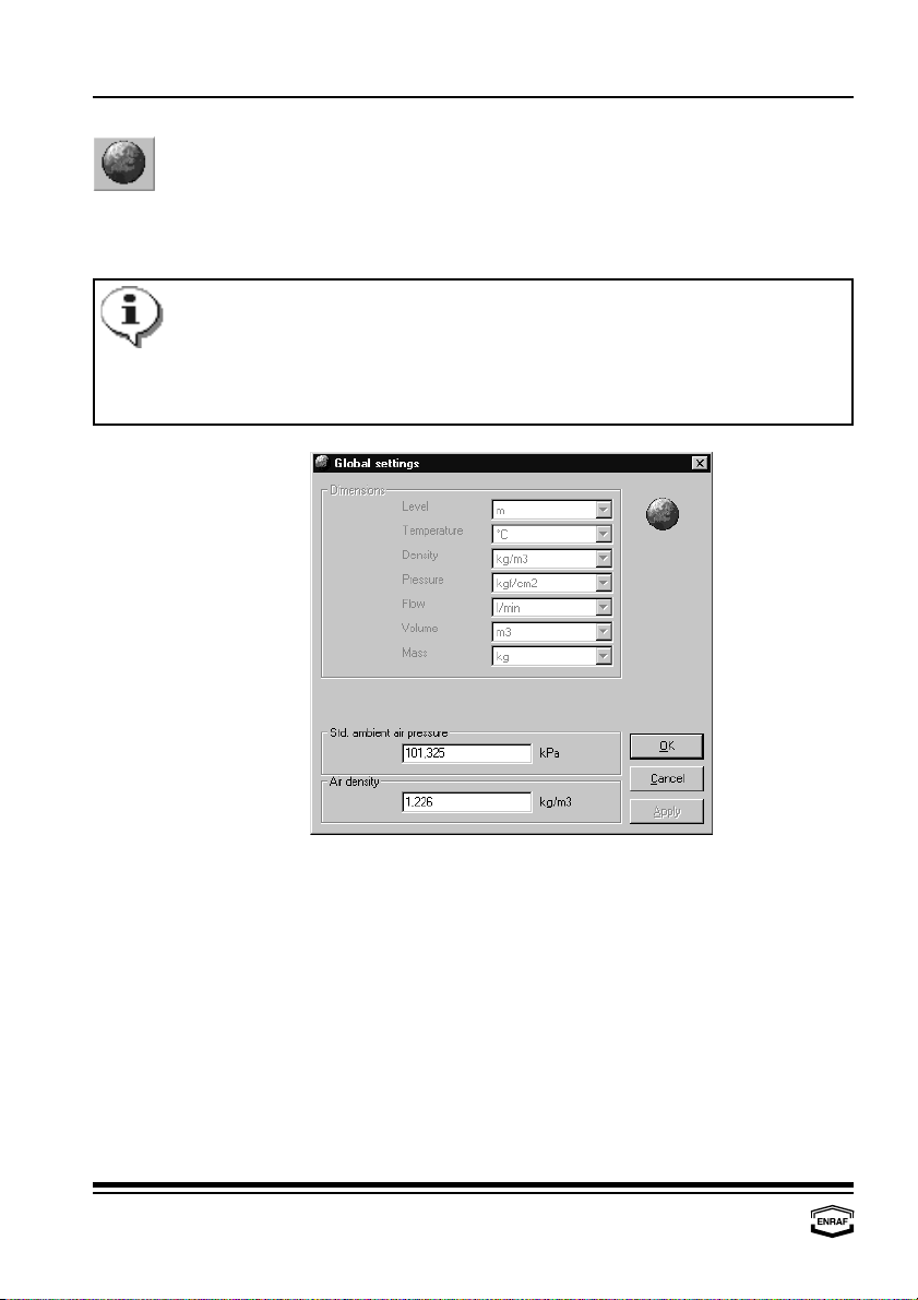
Global settings
This window automatically pops up after a site has been created. In
this window, global settings for the selected site can be programmed.
These global settings cover the way data is represented.
Dimensions
Level
Select: m, mm, ft, in, in/16, fis or 1/256 in
Temperature
Select: °C, °F
Density
Select: kg/m , °API, lbs/ft , dens60/60 or lbs/USgal
33
Pressure
Select: kgf/m , Pa, kPa or psi (lbf/in )
22
Flow
Select: m /min, m /h, l/min, bbls/min, bbls/h, USgal/min, Usgal/h
33
or UKgal/h
Volume
Select: l, m , USgal, bbls or UKgal
3
Mass
Select: kg, metric ton, USton, lbs or long ton
Std. ambient air pressure
Enter ambient air pressure in kPa (default = 101.325 kPa).
Air density
Enter air density in kg/m (default = 1.226 kg/m ).
33

Global settings
Instruction manual Ensite Pro Configuration Tool Page 15
After all global settings are made, the program warns the user that it
is not possible to change the settings anymore:
When confirmed, the program displays the following window:
The following buttons are available:
Select site.
A site gives an overview of the configuration at a specific customer’s
site.
Global settings.
Global settings cover the way data is represented, as well as some
local figures. These settings are valid for the particular site only.
Configure data inputs.
The data inputs collect data such as level, temperature, density and/or
pressure.
26
Configure tanks.
A tank is a (large) container to store liquids or gases.
Configure CIU Prime.
The CIU Prime is an interface between the field instrumentation and
inventory systems. To setup the CIU Prime, the port configuration
must be programmed.
Configure CIU Plus.
The CIU Plus calculates volume, standard volume, mass, density,
flow rate etc. To setup the CIU Plus, the port configuration must be
programmed.

Global settings
Page 16
Configure links.
After all individual components (CIU Prime, CIU Plus, tanks and data
inputs) have been configured, they have to be linked to each other.
Communication setup.
To be able to communicate via the configuration tool, communication
parameters must be set.
Download configuration.
The (new) programmed configuration must be downloaded for the CIU
Prime / Plus to work with.
Upload configuration.
The upload function is standard disabled in the toolbar.
Service note(s).
The build in text editor gives the possibility to store information about
the current site.
Set date and time.
The current date and time of the CIU Prime / Plus , can be (re-)set.
Print configuration.
The whole configuration can be printed to have a hard copy.
Show diagnostic data.
The build in diagnostic data views, reads and writes data direct from
and to the CIU Prime / Plus.
Tank viewer.
All measured and calculated data from one tank can be viewed.
Scan viewer.
The field scan can be viewed.
Help.
The build in help document assists at any time.
User privileges.
Access parameters for different users must be set.

Configure data inputs
Instruction manual Ensite Pro Configuration Tool Page 17
Configure data inputs
The data inputs (instruments in the field) collect data such as level,
temperature, density and/or pressure. The instruments measure the
data and transmit it upon request of higher layered systems.
Press the ‘Copy’-button to copy the highlighted data input from the list.
Only specific data must be changed afterwards.
When the data input is not in the list (yet), a new data input has to be
created. Press the ‘New’-button to add a data input:
Press the ‘Edit’-button to edit data from the highlighted data input:
- Gauge - Water - Density - Vapour
- Level - Temperature - Pressure - Scan
Press the ‘Delete’-button to remove the highlighted data input from the
list.

Configure data inputs
Page 18
A warning is generated before a log file is extracted while settings
have been entered already.
All dimensions in a gauge log file must be compatible with the
system dimensions.
Gauge
Gauge LOG file
Press the ‘Browse’-button to select a gauge log file.
Press the ‘Extract’-button to fill in the data from the gauge log file in
the next tabs.

Configure data inputs
Instruction manual Ensite Pro Configuration Tool Page 19
Gauge types ‘816' and ‘818' are only supported via 858 CIU.
Gauge type ‘829' is only supported in 867 emulation mode.
All three gauge types require the extended field address for 858 CIU
or 867 receiver (TOI 858 = P or R, TOI 867 = L).
Gauge type ‘999' is a generic Enraf gauge with no special
processing (default processing used).
General limits:
All instruments from one tank must be connected to the same
FieldPort.
Using BPM cards:
Up to 50 data inputs can be equally divided over the four FieldPorts
of the CIU Prime, with a maximum of 15 data inputs per line.
The instrument address on each port is free selectable between
00...99. The instrument address must be unique for all data inputs on
the same CIU.
Using RS232/485 cards:
Field addresses may contain 3 digit address numbers.
Gauge
Gauge type
Select:: Unknown, 802, 811, 812, 813, 816, 818, 829, 854, 865,
866, 872, 873, 877, 894, 973 or 999
Gauge details
Select:: hfor 854 gauges using the ZLQ record
(up to software version SPUA1.0)
- for 854 gauges
(with software version SPUA2.0 onwards)
Allowed gauge commands
Test gauge
Check if allowed (TG; 811, 854, 894 only)
Block gauge
Check if allowed (BL; 811, 854, 894 only)
Tank profile
Check if allowed (TP; 854, 894 only)
Gauge alarm test
Check if allowed (AT; 873 only)
Lock test
Check if allowed (LT; 811, 854, 894 only)
Water dip
Check if allowed (I3; 811, 854, 894 only)
Interface profile
Check if allowed (IP; 854, 894 only)
Verify command
Check if allowed (CA; 854, 894 only)
Reset gauge
Check if allowed (RS)
Interface 2 command
Check if allowed (I2; 854, 894 only)

Configure data inputs
Page 20
Level
Level enabled
Check to enable level scan.
0.1 mm level
Check to enable. This selection is only possible if the level dimension
resolution
is set to ‘m’or ‘mm’and if the gauge type is not 811, 813, 866 or 872.
Negative levels
Check to enable. This selection is only possible for gauge types
enabled
854, 872, 873 and 894.
No alarm when gauge in test
Check to disable gauge alarms during operational commands.
Level killed
Check to disable level scan.
Manual overwrite
Enter manual product level.
First enable level.
Level address
Enter level transmission address
Level TOI
Select: A, B, C, E or M
Level TOR
Select: B, J, L, M or ZLQ (the combination of level TOR ‘ZLQ’and
level type ‘Ullage’is not possible. With level type ‘Ullage’,
use level TOR ‘L’).
Table of contents
Other enraf Measuring Instrument manuals


Popular Measuring Instrument manuals by other brands


OHAUS
OHAUS MB90 quick start guide

Unipulse
Unipulse F320 Operation manual

Hanna Instruments
Hanna Instruments HI769828 instruction manual

TASKING
TASKING iSYSTEM ARM HSSTP II user manual

Hanna Instruments
Hanna Instruments HALO 2 HI9810302 instruction manual

LaserLiner
LaserLiner BeamControl-Master BCM operating instructions