Ensemble Designs Avenue 5820 Instruction manual

This data pack provides detailed installation, configuration and operation information for
the 5820 GPI/Serial Interface Module as part of the Avenue Signal Integration
System.
The module information in this data pack is organized into the following sections:
• Module Overview
• Applications
• Installation
• Cabling
• Module Configuration and Control
°Front Panel Controls and Indicators
°Avenue PC Remote Control
°Avenue Touch Screen Remote Control
• Troubleshooting
• Software Updating
• Warranty and Factory Service
• Specifications
5820-1
Model 5820
GPI/Serial Interface
Data Pack
Revision 2.1 SW v1.1.0
ENSEMBLE
DESIGNS

MODULE OVERVIEW
The 5820 GPI/Serial Interace module extends the capability of the Avenue control system
by enabling third party interfaces to control Avenue modules through memory register
recall. The 5820 provides General Purpose Interface control (GPI contact closure) over
modules located anywhere in the Avenue system. It also provides RS-232/RS-422 serial
interface access for use with show controllers and automation systems.
As shown in the block diagram below, GPI or serial inputs from a third party device, such
as an automation system, enter the 5820 module. They are mapped using the 5820 GPI
menus to any Avenue module in the network. When a GPI or serial command is received
by the 5820, it sends a configuration recall command to the corresponding Avenue module.
Using M2M™ (Module To Module) communication, the 5820 can communicate with any
other module in any Avenue frame on the network. That module then recalls the specfied
memory register.
An optional 1 RU control panel is available to serve as a shot box. It has eight illuminated
status pushbuttons that can also be used for manual override and status in automated
systems. Configuration and monitoring of the 5820 can also be done through an optional
Avenue Touch Panel, your web browser, and Avenue PC software.
Model 5820 GPI/Serial Interface Mod le
5820-2
GPI
Inputs Control
Processor
RS-232/
RS-422
Communication
With Other Modules
Through Avenue
Control System
5820 GPI/Serial Interface Mod le Block Diagram

APPLICATIONS
As shown below, the 5820 receives GPI information from a third party automation system.
The module is then configured to send messages to any Avenue module on the network to
recall memory registers. The optional Remote Control Panel shown here can monitor
status of the GPI inputs. From the serial interface port of the 5820, an external device can
also activate the same recall functions. The interface supports both RS-232 and RS-422
standards and uses a simple ASCII-based protocol for easy interconnection.
INSTALLATION
Plug the 5820 module into any one of the slots in the 1 RU or 3 RU frame. Install the
plastic overlay provided onto the corresponding group of rear BNC connectors associated
with the module location. Note that the plastic overlay has an optional adhesive backing
for securing it to the frame. Use of the adhesive backing is only necessary if you would
like the location to be permanent and is not recommended if you need to change module
locations. This module may be hot-swapped (inserted or removed) without powering down
or disturbing performance of the other modules in the system.
CABLING
Cabling to the 5820 module is done through the Control connector at the bottom of the
module backplane. Refer to the next section for control interface connections.
Model 5820 GPI/Serial Interface Mod le
5820-3
5820
5600
5430/5440
Automation
Avenue Control Network
GPIs
Optional Control Panel "Shot Box"
System
5820 GPI/Serial Interface Mod le Application
Model 5820 GPI/Serial Interface Mod le
5820-4
Control Interface Option
Three types of devices can control the 5820 module: An application specific control panel
(or multiple control panels), a customer-supplied GPI device and an external device (such
as a PC) using a Serial port connection. Connection to the Remote Control Panel and the
GPI device to the 5820 module and the cable pinouts for each application are given below.
Remote Control Panel
An optional 1 RU Remote Control Panel can serve as a shot box for firing GPIs. The
control panel has eight illuminated push buttons that can be used for manual
overrride and status in automated systems.
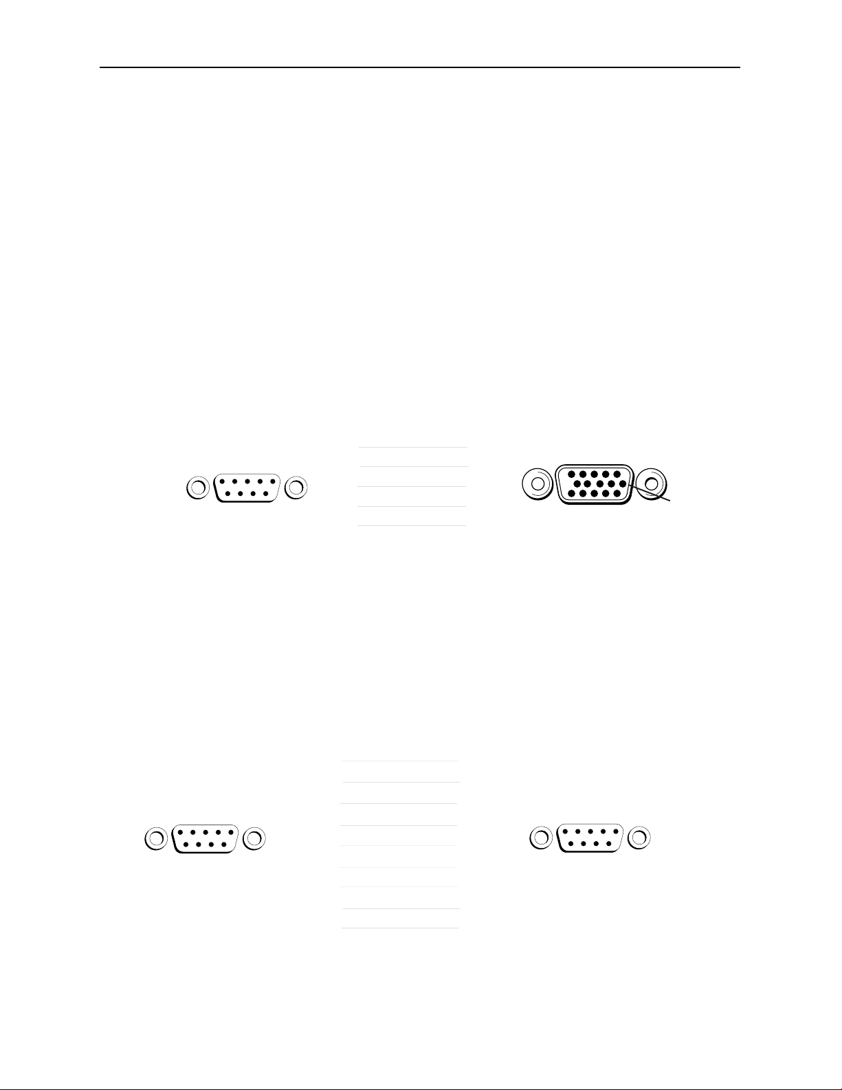
Connect the Remote Control Panel from the rear of the 5820 control panel (either DB
9-pin male connector) to the Control connector on the rear of the 5820 module (HDB
15-pin male) illustrated on the next page. The pinout for this connecting cable is
given in the diagram below.
The Remote Control Panel can be rack-mounted in a standard 19-inch equipment
rack. Connect the universal in-line power supply provided to the connector at the left
rear of the panel. The power supply is auto-sensing and requires no adjustments.
Up to eight Remote Control Panels can be connected in parallel for multipoint control.
Panels are connected together via the DB 9-pin loop-through connectors on each
panel. The cable to connect each panel is a DB 9-pin male to DB 9-pin male with
straight pin-to-pin connections as shown in the illustration below. This cable may be
purchased at any electronics supply store or constructed from the diagram. Note not
all pins are necessary for control panel connection but all pins can be connected.
Remote
Control Panel
DB-9 Male
5820 Control
Connector
HDB-15 Male
2
7
9
8
3
1
2
3
4
5
TX +
GND
RX +
RX –
TX –
Pin 1 Pin 1
Pin 11 Pin 6Pin 6
Control
Remote
Control Panel
DB-9 Male
Remote
Control Panel
DB-9 Male
1
2
3
4
5
6
7
8
9
1
2
3
4
5
6
7
8
9
Pin 1
Pin 6
Pin 1
Pin 6
Only bolded pins are ne essary
for ontrol panel ommuni ation,
however, all pins may be onne ted.

GPI Control
An external customer-supplied GPI device can be connected to the Control connector
on the rear of the 5820 module to trigger the GPI inputs by user-defined actions.
Connect the GPI control to the 5820 Control connector pins as shown below. Each
GPI pushbutton should be wired with closure to ground to trigger a crosspoint. It can
also simultaneously output status to light LEDs that are wired to ground as indicated
in the diagram below.
Model 5820 GPI/Serial Interface Mod le
5820-5
Customer -Supplied
GPI Device Switches
5820 Control
Connector
HDB-15 Male
1
2
3
4
5
6
7
8
15
14
12
11
10
9
8
7
3, 6, 13
Pin 1
Pin 11 Pin 6
Control
MODULE CONFIGURATION AND CONTROL
The eight GPI inputs on the 5820 module must be mapped to the Avenue modules to be
controlled using the menus in the Avenue PC application or an Avenue Touch Screen
Panel. Module status can also be read from the remote control menus or status is
indicated by front panel LEDs. The module indicators are illustrated in the Front Panel
Controls and Indicators section below.
For setting the parameters remotely using the Avenue PC option, refer to the Avenue PC
Remote Configuration section of this document.
For setting the parameters remotely using the Avenue Touch Screen option, refer to the
Avenue Touch Screen Remote Configuration section of this data pack following
Avenue PC.
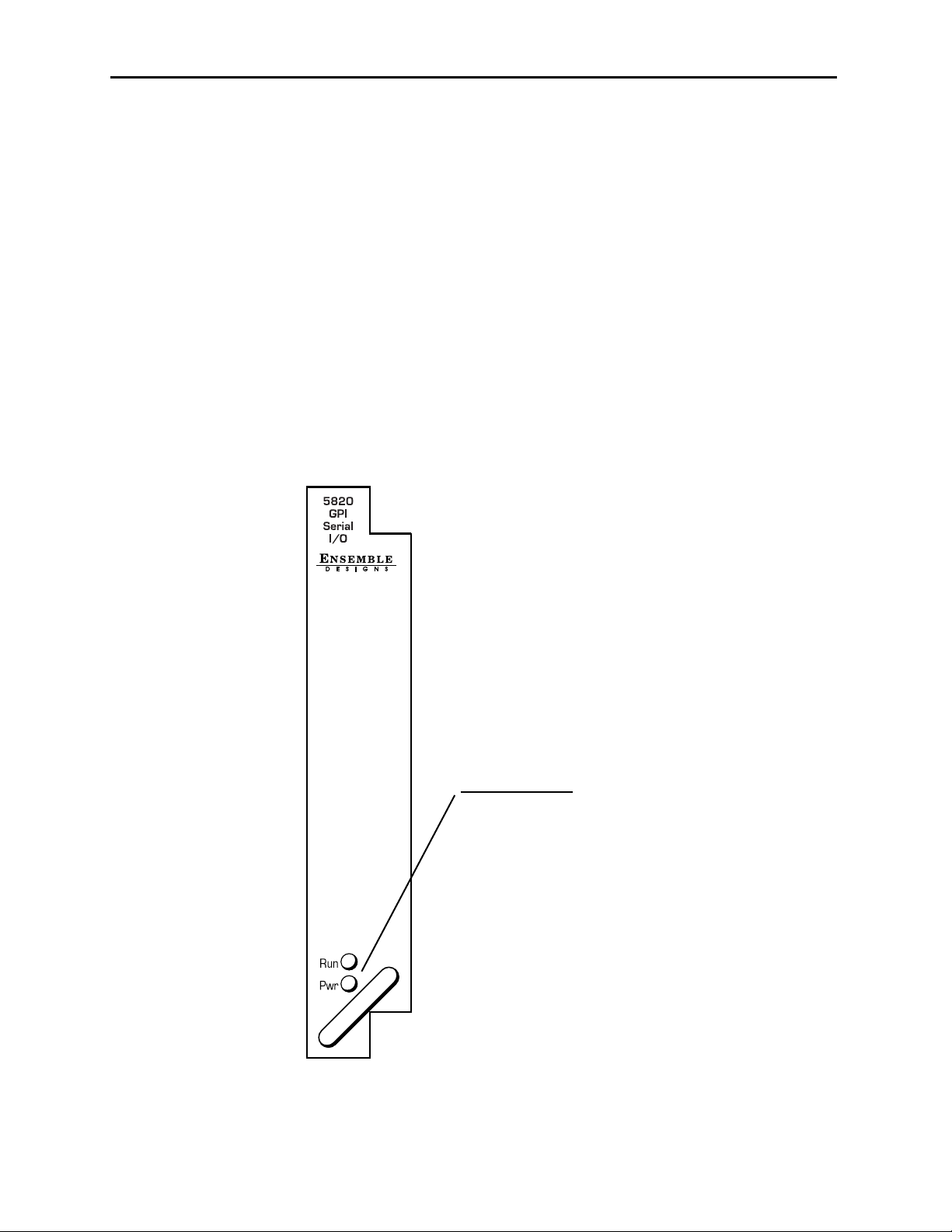
Front Panel Controls and Indicators
Each front edge indicator and switch setting is shown in the diagram below.
Model 5820 GPI/Serial Interface Mod le
5820-6
R n green LED:
OFF:
A power fault or halted CPU
ON:
A halted CPU
FAST BLINK:
CPU Run error
SLOW BLINK:
System OK. (If SPI ontrol is
a tive from the main frame
System Control Module, all
R n indi ators will be syn-
hronized.).
Aven e PC Remote Config ration
The Avenue PC remote control status menu for this module is illustrated and explained
below. For more information on using Avenue PC, refer to the Avenue PC Control
Application Software data pack that came with the option.
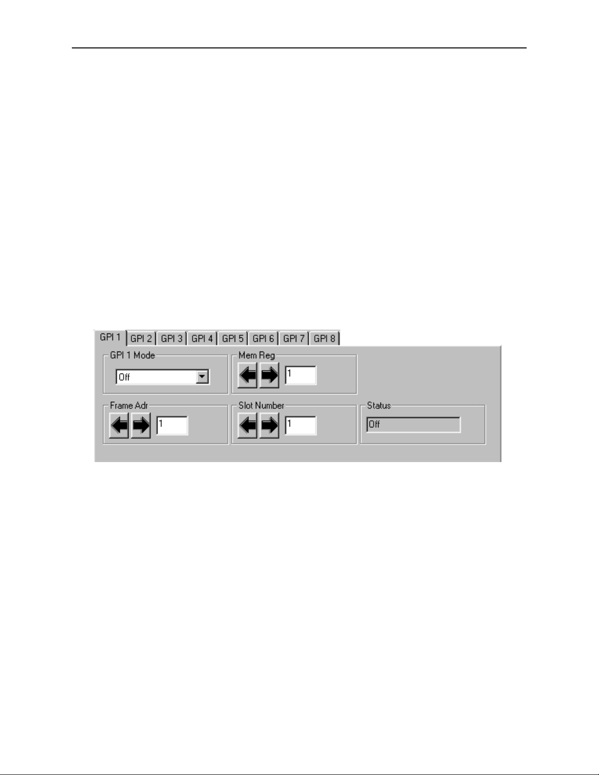
5820 Avenue PC Menus
There are eight GPI menus in the Avenue PC application, GPI 1 – GPI 8, one to corre-
spond to each available GPI port. Set the parameters for each of the GPI inputs as follows:
•GPI 1 – 8 Mode – set to On, GPI High (GPI triggered by pulse going high) or GPI
Low (GPI triggered by pulse going low).
•Mem Reg – select the memory register (1 – 5) on the corresponding module that
has been configured for recall.
•Frame Adr – enter the AveNet address of the frame containing the module you
wish to control.
•Slot Number – enter the Slot Number of the module in the selected frame.
AStatus box shows the current status of the GPI port as Off (GPI turned off), Connect
(5820 is successfully communicating with the module), or Fail (5820 cannot communicate
with selected module).
5820-7
Model 5820 GPI/Serial Interface Mod le

Model 5820 GPI/Serial Interface Mod le
Aven e To ch Screen Remote Config ration
The Avenue Touch Screen remote control status menu for this module is illustrated and
explained below. For more information on using Avenue Touch Screen, refer to the Avenue
Touch Screen data pack that came with the option.
5820 Avenue PC Menus
There are eight GPI menus in the Avenue touch Screen Panel application, GPI 1 – GPI 8,
one to correspond to each available GPI port. Set the parameters for each of the GPI
inputs as follows:
•GPI 1 – 8 Mode – set to On, GPI High (GPI triggered by pulse going high) or GPI
Low (GPI triggered by pulse going low).
•Mem Reg – select the memory register (1 – 5) on the corresponding module that
has been configured for recall.
•Frame Adr – enter the AveNet address of the frame containing the module you
wish to control.
•Slot Number – enter the Slot Number of the module in the selected frame.
AStatus box shows the current status of the GPI port as Off (GPI turned off), Connect
(5820 is successfully communicating with the module), or Fail (5820 cannot communicate
with selected module).
5820-8

TROUBLESHOOTING
As a troubleshooting aid, power and CPU status can be easily monitored from the front
panel of this module using the indicators explained in the previous section.
The following status items can be monitored using the Avenue Touch Screen Control Panel
or PC Application:
• Power status
• Slot ID, Software Version and Board Revision
Refer to the overall troubleshooting tips given below for the 5820 module:
No status lights are lit on front panel:
• Check that frame power is present (green LED{s} on frame power supplies).
• Check that module is firmly seated in frame. Try removing it and plugging
it in again to make sure it is seated properly.
Can’t control module:
• Check status of CPU Run green LED. Should be blinking slowly and in
unison with other modules if System module is present. If not, try removing
it and plugging it in again.
• System module may not be working properly if installed.
You may also refer to the technical support section of the Ensemble or Graham-Patten
web sites for the latest information on your equipment at the URLs below:
http://www.ensembledesigns.com/support
SOFTWARE UPDATING
Software upgrades for each module can be downloaded remotely if the optional System
Control module is installed. These can be downloaded onto your PC and then Avenue PC
will distribute the update to the individual module. (Refer to the Avenue PC documenta-
tion for more information) Periodically updates will be posted on our web site. If you do
not have the required System Control Module and Avenue PC, modules can be sent back
to the factory for software upgrades.
Model 5820 GPI/Serial Interface Mod le
5820-9

5820-10
WARRANTY AND FACTORY SERVICE
Warranty
This module is covered by a five year limited warranty, as stated in the main Preface of
this manual. If you require service (under warranty or not), please contact Ensemble
Designs and ask for customer service before you return the unit. This will allow the
service technician to provide any other suggestions for identifying the problem and
recommend possible solutions.
Factory Service
If you return equipment for repair, please get a Return Material Authorization Number
(RMA) from the factory first.
Ship the product and a written description of the problem to:
Ensemble Designs, Inc.
Attention: Customer Service RMA #####
870 Gold Flat Rd.
Nevada City, CA. 95959 USA
(530) 478-1830
Fax: (530) 478-1832
http://www.ensembledesigns.com
Be sure to put your RMA number on the outside of the box.
Model 5820 GPI/Serial Interface Mod le

Model 5820 GPI/Serial Interface Mod le
SPECIFICATIONS
5820 GPI/Serial Interface
Input Signal:
Number: Eight GPI
One RS-232/RS-422
General Specifications
Power Consumption: < 5.0 Watts
Temperature Range: 0 to 40 degrees C ambient (all specs met)
Relative Humidity: 0 to 95% noncondensing
Altitude: 0 to 10,000 ft
Fusing: 1.5 Amp PTC resettable fuse
Setup: User Selectable
Due to ongoing product development, all specifications subject to change.
5820-11
Table of contents
Other Ensemble Designs Control Unit manuals


