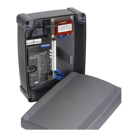
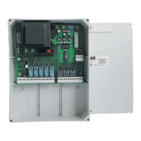
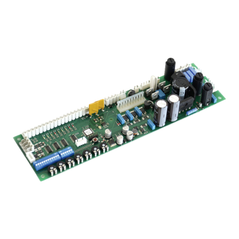
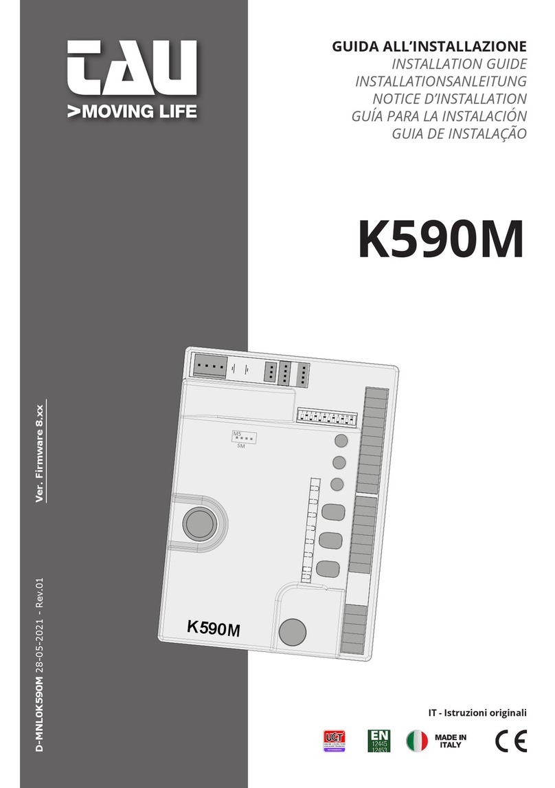
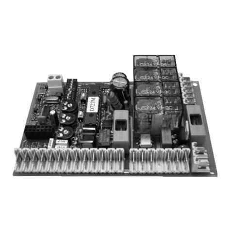
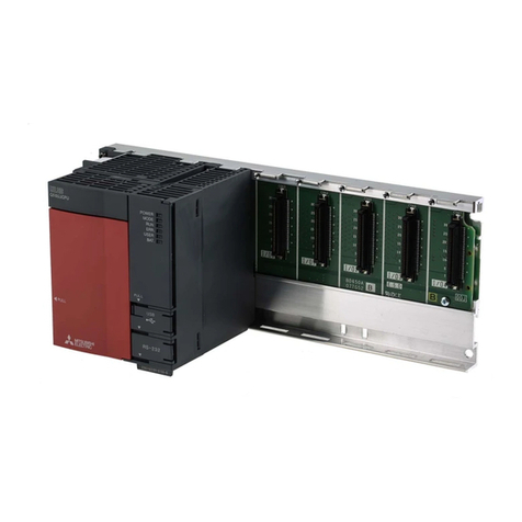
tau DC18 User manual

INSTALLATION GUIDE
GUIDA ALL’INSTALLAZIONE
NOTICE D’INSTALLATION
IT - Istruzioni originali
DC18
DC18-M
1 2 3 4
DC18-P
D-MNL0DC18 08-05-2023 - Rev.08

2
DC18 WIRING DIAGRAM WITH ACTIVATION
AND SAFETY SENSORS
DC18-M
8
1
ON 2 3 4
910
11
12
1314
15
16
17
18
1920
21
22
23
24
25
26
27
J4
J9
J10
J11
J12 J13 J14
J15
J16
ENCODER
ENCODER
-
+
A
B
SEL.
B2
SEL.
B1
SEL. B0
COMMON (green and blue)
COMMON
-
TEST SENSOR (brown)
NOT USED
-
GND (black)
EMERGENCY
EMERGENCY
START
20
18
START
20
19
123 4 567
DOORSS340/1023T
123 4 567
DOORSS340/1023T
123 4 123 4
+TEST SENSOR (grey)
+ 24Vcc (red)
RADAR OUT. N.A. (white)
SECURITY OP. N.C.
SECURITY CL. N.C. (yellow)
RADAR IN. N.A.
SENSOR OPEN SIDE
SENSOR CLOSED SIDE
SENSOR OPEN SIDE
SENSOR CLOSED SIDE
DOORRADM DOORRADMU
1234
BA-+
DL 1
LED3
LED2
ENGLISH

3
DC18-P
1
2
67
J1
J2
J3
J4
J5 J6 J7
J8
3
FASE
NEUTRO
SCHEDA CARICA BATTERIE
BATTERIASERR.ELET.MOTORE
SECONDARIO TF PRIMARIO TF
F1
3,15 A
F2
6,3 A
F3
2 A
LED4
LED5
TERRA
230V ac
SEZIONATORE
ALIMENTAZIONE DI RETE
MOTOR (+)
MOTOR (-)
ELECTROLOCK
+
-
BATTERY
+
BATTERY
* su richiesta
115 Vac
+/-10%, 60Hz
ENGLISH

4
DC18-M
8
1
ON 2 3 4
910
11
12
1314
15
16
17
18
1920
21
22
23
24
25
26
27
J4
J9
J10
J11
J12 J13 J14
J15
J16
ENCODER
ENCODER
-
+
A
B
SEL.
B2
SEL.
B1
SEL. B0
COMMON
COMMON
-
TEST SENSOR
NOT USED
-
GND
EMERGENCY
EMERGENCY
START
20
18
START
20
19
123 4 567
DOORSS340/1023T
123 4 567
DOORSS340/1023T
+TEST SENSOR
+ 24Vcc
RADAR OUT. N.A.
SECURITY OP. N.C.
SECURITY CL. N.C.
RADAR IN. N.A.
SENSOR OPEN SIDE
SENSOR CLOSED SIDE
1234
BA-+
DL 1
LED3
LED2
+-
OUTSIDE SENSOR
S-10DOORRAD2
TEST
+-
POWER
DC18 WIRING DIAGRAM WITH ACTIVATION
AND SAFETY SENSORS DOORRAD2 AND
DOORSS340/1023T
ENGLISH

5
DC18-P
1
2
67
J1
J2
J3
J4
J5 J6 J7
J8
3
FASE
NEUTRO
SCHEDA CARICA BATTERIE
BATTERIASERR.ELET.MOTORE
SECONDARIO TF PRIMARIO TF
F1
3,15 A
F2
6,3 A
F3
2 A
LED4
LED5
TERRA
230V ac
SEZIONATORE
ALIMENTAZIONE DI RETE
MOTOR (+)
MOTOR (-)
ELECTROLOCK
+
-
BATTERY
+BATTERY
+-
OUTSIDE SENSOR
S-10DOORRAD2
TEST
+-
POWER
Mors. 10 - Brown
Mors. 8 - Grey
Mors. 15 - Yellow
Mors. 11 - Green
Mors. 11 - Blue
Mors. 13 - White
Mors. 17 - Black
Mors. 16 - Red
* su richiesta
115 Vac
+/-10%, 60Hz
ENGLISH

6
WARNINGS
This manual has been especially written for use by qualied installers. No information given in
this manual can be considered as being of interest to end users. This manual is enclosed with
control unit DC18 and may therefore not be used for dierent products!
Important information:
Disconnect the panel from the power supply before opening it.
The DC18 control unit has been designed to control an electromechanical gear motor for auto-
mating gates and doors of all kinds.
Any other use is considered improper and is consequently forbidden by current laws.
Please note that the automation system you are going to install is classied as “machine con-
struction” and therefore is included in the application of European directive 2006/42/EC (Machi-
nery Directive). This directive includes the following prescriptions:
- Only trained and qualied personnel should install the equipment;
- the installer must rst make a “risk analysis” of the machine;
- the equipment must be installed in a correct and workmanlike manner in compliance with all
the standards concerned;
- after installation, the machine owner must be given the “declaration of conformity”.
This product may only be installed and serviced by qualied personnel in compliance with cur-
rent, laws, regulations and directives.
When designing its products, TAU observes all applicable standards (please see the attached
decla- ration of conformity) but it is of paramount importance that installers strictly observe the
same stand- ards when installing the system.
Unqualied personnel or those who are unaware of the standards applicable to the “automatic
gates and doors” category may not install systems under any circumstances.
Whoever ignores such standards shall be held responsible for any damage caused by the
system!
Do not install the unit before you have read all the instructions.
INSTALLATION
Before proceeding, make sure the mechanical components work correctly. Also check
that the gear motor assembly has been installed according to the instructions. Then
make sure that the power consumption of the gear motor is not greater than 3A
(otherwise the control panel may not work properly).
THE EQUIPMENT MUST BE INSTALLED “EXPERTLY” BY QUALIFIED PERSONNEL AS REQUIRED
BY LAW.
Note: it is compulsory to earth the system and to observe the safety regulations that are
in force in each country.
IF THESE ABOVE INSTRUCTIONS ARE NOT FOLLOWED IT COULD PREJUDICE THE PROPER
WORKING ORDER OF THE EQUIPMENT AND CREATE HAZARDOUS SITUATIONS FOR PEO-
PLE. FOR THIS REASON THE “MANUFACTURER” DECLINES ALL RESPONSIBILITY FOR ANY
MALFUNCTIONING AND DAMAGES THUS RESULTING.
ENGLISH

7
1. ELECTRIC ARRANGEMENTS
NOTE:
The grey part indicates
the survey zone of radar
and sensors.
The number of cables
and the relevant section
in mm is indicated for
every device.
1
3
4
8
9
6
5
27
1) EXTERNAL RADAR (4x0,5mm)
2) INTERNAL RADAR (4x0,5mm)
3) OPENING CONTROL (2x0,5mm)
4) PROGRAM SELECTOR (4x0,5mm)
5) SAFETY SENSOR FOR CLOSING (6x0,5mm)
6) SAFETY SENSOR FOR OPENING(6x0,5mm)
7) BRINK OPERATOR (mains power supply 3x1,5mm)
8) ELECTRIC LOCK (2x1mm)
9) FLOOR STOP
• The power supply line must be protected against short circuit and dispersion to
ground.
• On the power supply mains, provide for an omni-polar switch/selector with
contact opening distance of at least of 3 mm.
• Use self-extinguishing cables for electric connections.
• Separate the mains power supply line from the very-low voltage line relative to
control and safety accessories.
• On the plastic side panels of the Brink operator there are the holes that must be
broken open, through which the electric cables must be inserted. The installer
must made the power supply cable stable inside the operator and, particularly,
limit the peeling of cable primary sheath so that the air and surface distances
are not reduced if a connector detaches from the terminal.
• If operator is installed on a door leaf, perform electric connection by a bran-
ching box with suitable exible unions and pipes, available on the market.
ENGLISH

8
CONTROL PANEL FOR AUTOMATIC SWING DOOR
• MICROPROCESSOR-BASED CONTROLLER
• ENCODER SENSOR FOR SELF-LEARNING OF TRAVEL
• CONNECTOR FOR BATTERY
• DIAGNOSTICS LEDS
ATTENTION:
- do not use single cables (with one single wire), ex. telephone cables, in order to avoid
breakdowns of the line and false contacts;
- do not re-use old pre-existing cables;
TESTING
Once the connection is completed:
TECHNICAL CHARACTERISTICS
Board power supply 230 V AC - 50 Hz*
Fast acting fuse entrance 230V AC (F5 - 5x20) 3.15A
Fast acting fuse for protection of auxiliary circuits 24 V CC
(F1 - 5x20) 2 A
Fast acting fuse for motor protection 40Vcc (F2 - 5x20) 6,3 A
Motor power supply circuits voltage 40 V DC
Auxiliary device circuits supply voltage 24 V DC
Logic circuits supply voltages 5 V DC
Operating temperature -20 °C ÷ +55 °C
* On request 115 Vac +/- 10%, 60Hz
WORKING PROGRAMS
Six dierent working programs can be selected (can be set by mechanical selector or by
T-SIDETD programmer):
• “ENTRAMBI I SENSI” (AUTO)
• “SOLO USCITA” (EXIT ONLY)
• “SEMPRE CHIUSA” (HOLD CLOSE)
• “MANUALE” (
• “SEMPRE APERTA” (HOLD OPEN)
• “SOLO ENTRATA” (ENTRY ONLY)
Program Description Active inputs Remarks
“ENTRAMBI I SENSI”
(AUTO) Two-Way Trac
Outside Radar
Inside Radar
Start / PP
Emergency
ENGLISH

9
“SOLO USCITA”
(EXIT ONLY) Exiting Trac
Inside Radar
Start / PP
Emergency
“SEMPRE CHIUSA”
(HOLD CLOSE)
Door always closed
(time to exit 10 sec.) Emergency
“MANUAL”
To move the door
manually without
controlling the motor
“SEMPRE APERTA”
(HOLD OPEN)
Door remains always
open
“SOLO ENTRATA”
(ENTRY ONLY) Entering Trac
Outside Radar
Start / PP
Emergency
CONNECTIONS TO TERMINAL BOARD
CONNETTORE J1 - power input connection 230V 50hz:
Terminals
Input/Output Description
1PHASE 230V AC
2GROUND
3NEUTRAL 230V AC
* On request 115 Vac +/- 10%, 60Hz
CONNETTORE J2 - transformer primary connector.
CONNETTORE J3 - transformer secondary connector.
CONNETTORE J4 - connector to link the two electronic boards
CONNETTORE J5 - motor connection.
CONNETTORE J6 - terminal used to command an electric lock; to be combined with a relay
in order to activate the lock.
Terminals Function Description
6 - 7 ELECTRIC LOCK 6= + 24V DC
7 = - GND
CONNETTORE J14 - connection for safety sensors test:
Terminals Function Description
8-10 TEST SENSOR 8 = + 24V DC
10 = - GND
9 NOT USED
ENGLISH

10
CONNETTORE J13 - sensor connection:
Terminals Function Description
11 - 12 INTERNAL SENSOR
(N.O. contact)
Opens in “EXIT ONLY” and “AUTO”.
Door won’t close until sensor is released.
11 - 13 EXTERNAL SENSOR
(N.O. contact)
Opens in “ENTANCE ONLY” and “AUTO”.
Door won’t close until sensor is released.
11 - 14 OPENING SAFETY SENSOR
(N.C. contact)
Stops the door if it detects an obstacle/person
during the opening phase, and it resumes opening
when the obstacle/person is removed.
11 - 15 CLOSING SAFETY SENSOR
(N.C. contact)
Stops the door if it detects an obstacle/person during
the closing phase and it reopens.
16 - 17 SENSORS POWER SUPPLY 16= + 24V DC
17 = - GND
CONNETTORE J7 - battery connector.
CONNETTORE J8 - battery charger board connector.
CONNETTORE J9 - connector for T-WIFI.
CONNETTORE J11 - connector for lid button.
CONNETTORE J12 - connection for T-LINESELF and EMERGENCY button:
18 - 20
EMERGENCY
(N.C.)
(20= commun)
Closed
Opens in any program, except in “LOCKED”.
When dip # 1 on SW1 is set on ON opens also in
“LOCKED”.
Opening None.
Closing Reverts motion and opens.
Open Door won’t close until input is released.
In pause None.
19 - 20
OPEN/START
(N.O.)
(20= commun)
Closed Open.
Opening None.
Closing Reverts motion and opens.
Open None.
In pause None.
20 - 21
22 - 23
MECHANICAL
SWITCH
20= Commun
21= Switch B0
22= Switch B1
23= Switch B2
Connections:
Selector Control Panel
120
2 21
3 22
4 23
WARNING: In case neither the mechanical selector it is necessary to jumper
wire terminals 20 - 22.
ENGLISH

11
SM
0419
M1 M2
1 2 3 4
SHOLD OPEN = Keeps door fully open.
AUTO = All Opening Inputs enabled
EXIT ONLY = Disables Outside Radar.
MANUAL = To move the door manually with-
out controlling the motor.
LOCK = Keeps door closed, allowing
opening only with EMERGENCY
Input (with Dip #1 on SW1 on
ON).
CONNETTORE J10 - connection to T-SIDETD (see its manual).
Terminals Function Description
24 POSITIVE T-SIDETD POWER + 5 V DC
25 A T-SIDETD SIGNAL signals the communication between T-SIDETD
and DC20
26 B T-SIDETD SIGNAL signals the communication between T-SIDETD
and DC20
27 NEGATIVE T-SIDETD POWER - 5 V DC
CONNETTORE J16 - encoder connection.
STROKE SETUP
To carry out the STROKE SETUP it is necessary to use the T-SIDETD digital keyboard
Before proceeding with the SETUP of the stroke, use the dipswitch to select the type of au-
tomatic swing door and its characteristics:
1AUTOMATION TYPE ON T-SIDE-S gearmotor with closing spring
OFF T-SIDE gearmotor without closing spring
2WEIGHT OF THE DOOR ON Heavy door max 110 Kg
OFF Light door up to 80 Kg
3MASTER/SLAVE ON To activate the MASTER/SLAVE mode for double swing
leaf automations
OFF For automations with single swing leaf
4MASTER/SLAVE ON To dene the SLAVE status
OFF To dene the MASTER status
IMPORTANT: during the initialization procedure no obstacles must be placed in the
doorway and in the radar detection eld, otherwise the procedure fails and must be
repeated. Furthermore, the door must not be manually assisted and other parame-
ters must not be changed with the digital keyboard.
At the rst installation, power up the control unit and once the digital keyboard is connected,
ENGLISH

12
it will propose the SETUP procedure automatically. To start the procedure, press the P1 key.
To start the SETUP of the stroke, press the P1 key, the DL1 LED will start to ash yellow and,
subsequently, the door will start a slow opening and closing maneuver to nd the opening
and closing limit switches. At the end, the door will perform a complete opening and closing
maneuver at standard speed. Once the setup is done, the door must be closed and the DL1
LED must ash green.
The automation will therefore work with the standard factory settings. In case an interven-
tion is required to change the operating parameters, the digital keyboard must be used by
accessing the various menus
SENSOR TEST SETTING
• Use only sensors which feature testing wires, connecting these to the wire terminals 8
and 10 of the controller DC18;
• Set DIP #15 and #16 on to ON in order to enable the test;
• Test will be performed at the beginning of each cycle (except when reversing motion).
BATTERY CHARGER KEY
Key: LED steady on; LED ashing;
GREEN LED – battery charger
status
o battery charger o;
ashing every 2 seconds initial slow charge;
continuous ashing under fast charge;
ashing every 4 seconds in backup;
steadily lit battery charged;
RED LED – fault diagnostics
o everything OK;
steadily lit FAULTY battery (cell voltage < than the minimum
or …..)
continuous ashing short circuit
ashing every 2 seconds battery not connected
AUTOMATIC OPERATION RESETTING - REALIGNMENT
When the board is powered or if the status of the inputs is unknown, the software must
realign the automation to determine the initial position.
The direction of the realignment depends on the program selected and the command given.
ATTENTION: if there are any “motor” alarms, the automatic reset timer is inhibited.
ENGLISH

13
DIAGNOSTICS LEDs AND BUZZER
DL1 DIAGNOSTIC
DL2 POWER SUPPLY 12 V
DL3 POWER SUPPLY 5 V
DL4 AUX POWER SUPPLY 24 V DC
DL5 Red LED for signaling MOTOR POWER SUPPLY 40V DC
DL1 LED ERRORS
Key: LED steady on; LED ashing;
Automation warnings:
green - ashing every 4 seconds automation closed – everything OK;
green - continuous ashing automation moving (opening/closing);
green – quick ashing automation pausing;
green – steadily lit automation open;
/ alternating green/red - warning setup to be performed
yellow – QUICK ashing setup in progress
/ green/yellow – QUICK ashing Parameter recalculation in progress / program
change
Allarmi automazione:
red - 1 error photocell test failed
red - 2 error obstacle present
red - 3 error no voltage
red - 4 error automation in unknown status
red - 5 error automation timeout
red - 6 error incorrect communication MASTER/SLAVE
red - 7 error wrong parameters (generic error)
red - 8 error incorrect winter stroke parameters
Motor alarms:
yellow - 1 error encoder faulty or disconnected motor 1
yellow - 2 error motor 1 faulty or disconnected
yellow - 3 error motor 1 absorption exceeding the limits
yellow - 4 error obstacle detected by encoder 1
yellow - 5 error encoder faulty or disconnected motor 2
yellow - 6 error motor 2 faulty or disconnected
yellow - 7 error motor 2 absorption exceeding the limits
yellow - 8 error obstacle detected by encoder 2
ENGLISH

14
TROUBLESHOOTING
MALFUNCTION POSSIBLE CAUSE ACTION
DL1 ashes green/
red alternately. LEARNING Missing. Perform LEARNING as described in
LEARNING section.
During LEARNING
motor won’t move.
Safety or Command Inputs
are not correctly connect-
ed.
Check connections on wire terminals.
Safety or Command Inputs
are in use.
Remove obstacle from Sensor or Photo-
cells detection range.
With Mechanical
Switch connected,
door can’t complete
LEARNING process.
Mechanical Switch is set
on “SOLO ENTRATA” (EN-
TRY ONLY).
Set Mechanical Switch either on “EN-
TRAMBI I SENSI” (AUTO) or “BLOCCATA
CHIUSA” (LOCKED).
Door opens but not
closes.
Sensor or Photocell detect
an obstacle.
Remove obstacle from Sensor or Photo-
cells detection range; check eciency of
detection devices.
Dip # 3 on SW1 is set on
OFF and battery is not
connected, faulty or low.
Check connection and eciency of the
battery operated anti-panic device.
Doors stops and re-
vert operation. The
following cycle is per-
formed at reduced
speed.
The door found an ob-
stacle. Remove the obstacle.
The following cycle is per-
formed at reduced speed.
The door has excessive friction which
is seen as an obstacle Check the door
movement, if necessary adjust trimmers
TR3 and TR4 (force).
Door opens a little
bit, then closes at
reduced speed.
Encoder is damaged or
not properly connected.
Check the encoder 4-pole connector is
inserted.
DL1 1 yellow ashes Encoder not working Check the encoder cable or replace the
encoder as required.
Door won’t open in
“BLOCCATA CHIUSA”
(LOCKED) program
with EMERGENCY
input.
Controller is set on “BLOC-
CATA CHIUSA” (LOCK) pro-
gram and DIP # 1 on SW1
is set on OFF.
Select a dierent program, or set the
DIP # 1 on SW1 to ON to enable EMER-
GENCY input.
Battery is connected,
but door won’t open
in case of power
failure.
DIP # 3 on SW1 is set on
OFF.
Set DIP # 3 on SW1 on ON to enable
automatic opening in case of power
failure.
DOUBLE LEAF SWING DOOR
To manage the functioning of a double leaf swing door, two operators are needed: one cong-
ured as Master and the other one congured as Slave.
In the case of overlapping leaves, congure as Master the operator applied to the swing leaf
(the one that opens rst).
ENGLISH

15
In the case of a swing door with two overlapping closing leaves and installed on
emergency exits, the installer must measure the force required to open both leaves
of the door by manually pushing the Slave leaf in the direction of escape (most un-
favorable).
The force required to open the door manually must not exceed 150N and must be
measured on the main edge, right angle to the leaf, at a height of 1000±10mm.
If the measured force should exceed the limit of 150N, apply the emergency break-
out symbol only on the main leaf (Master) of the door.
ELECTRICAL CONNECTIONS FOR DOUBLE LEAF DOOR
Make the electrical connections to the operators (see paragraph “Electrical connections”), con-
sidering that the command actuators for door opening, the program selector and the electric
lock must be connected to the Master operator.
The safety sensors installed on the master leaf must be connected to the Master operator, the
safety sensors installed on the slave leaf must be connected to the Slave operator.
If the door has a double electric lock to block each leaf individually, connect the electric lock
that blocks the slave leaf to the Slave operator..
ALIMENTAZIONE
DI RETE 230 V ac *
TASTIERA
DIGITALE
SENSORE
DI APERTURA
COMANDO
OPEN
OPERATORE MASTER
CABLAGGIO
M/S
OPERATORE SLAVE
SENSORI DI
SICUREZZA
PILOTAGGIO
ELETTROSERRATURA
MASTER
PILOTAGGIO
ELETTROSERRATURA
SLAVE
ANTA 1 (MASTER) ANTA 2 (SLAVE)
SENSORI DI
SICUREZZA
MASTER
The Master and Slave operators must be connected to each other as shown in the
gure
Connect to the Master operator with the T-SIDETD digital keyboard
ENGLISH

16
DC18-M SLAVE
8
910
11
12
1314
15
16
17
18
1920
21
22
23
24
25
26
27
J4
J10
J12 J13 J14
-
A
B
DC18-M MASTER
8
910
11
12
1314
15
16
17
18
1920
21
22
23
24
25
26
27
J4
J10
J12 J13 J14
-
+
A
B
BA-+
ENGLISH

17
ENGLISH

18

19

Via Enrico Fermi, 43 - 36066 Sandrigo (VI) - Italy
Tel +39 0444 750190 - Fax +39 0444 750376
[email protected] - www.tauitalia.com
Foglietto illustrativo
CARTA - Raccolta dierenziata. Segui le indicazioni del tuo comune. (N.B.: togliere i punti metallici)
Instruction leaet
PAPER - Waste separation. Follow the instructions of your city hall. (Note: remove the staples)
22
PAP
This manual suits for next models
2
Table of contents
Other tau Control Unit manuals
Popular Control Unit manuals by other brands
bee
bee 851E Operating and assembly instruction

Quectel
Quectel QuecOpen AG525R-GL Hardware design
olympia electronics
olympia electronics i-OLEG LumiGate GR-7610/V2 manual
Luna
Luna T-Ray 5000 user manual

Agilent Technologies
Agilent Technologies N5532A User's and service guide
GGM
GGM GUS Series Operation manual
