ensto Wallbox User manual

EN
Ensto Wallbox
Installation Instructions
User Guide
RAK111B_EN
2023-09-14
© 2023 Ensto Building Systems

RAK111B_EN / 2023-09-14
2 / 32
Contents
Installation Instructions
1. Safety instructions.......................................................................................................................................................... 3
2. Description of symbols................................................................................................................................................. 3
3. Abbreviations................................................................................................................................................................... 4
4. Delivery contents............................................................................................................................................................ 4
5. Accessories........................................................................................................................................................................ 5
6. Mounting instructions.................................................................................................................................................. 8
6.1. Before installation............................................................................................................................................ 8
6.2. Wall mounting with wall bracket................................................................................................................ 9
6.3. Ground mounting on concrete casting with ground mounting pole.........................................10
6.4. Ground mounting on concrete foundation with ground mounting pole.................................11
6.5. Ground mounting on Unimi concrete foundation.............................................................................12
6.6. Attaching charging station to mounting pole EVTL43.00..............................................................14
7. Electrical connections................................................................................................................................................. 15
7.1. Wiring instructions........................................................................................................................................ 15
7.2. Power supply................................................................................................................................................... 16
8. Commissioning..............................................................................................................................................................18
8.1. View of the component layout on the control unit............................................................................18
8.2. Connecting to the charging station........................................................................................................ 19
8.3. Ethernet connections................................................................................................................................... 20
8.4. WiFi coverage area.........................................................................................................................................20
9. Technical data................................................................................................................................................................ 21
10. Code key........................................................................................................................................................................ 23
11. Dimensional drawing............................................................................................................................................... 24
12. Installation / Commissioning checklist.............................................................................................................. 26
13. Maintenance / Preventive maintenance instructions................................................................................... 27
14. Testing instructions for the electric protective device................................................................................. 28
15. Troubleshooting......................................................................................................................................................... 28
16. Warranty........................................................................................................................................................................ 29
17. Declaration of Conformity...................................................................................................................................... 29
18. Disposal......................................................................................................................................................................... 29
User Guide
19. User interfaces.............................................................................................................................................................30
20. Charging........................................................................................................................................................................30
20.1. Free charging.................................................................................................................................................30
20.2. Charging with RFID..................................................................................................................................... 31
RAK111B_EN / 2023-09-14 3 / 32
Installation Instructions
1. Safety instructions
Electrically skilled person
• The installation must only be done by a qualied professional.
• Read these instructions carefully before you install, operate or maintenance the charging station.
• Obey the instructions in this manual and make sure that the installation complies with national
safety regulations, installation methods and restrictions.
• The information provided in this manual in no way exempts the installer or user from responsibil-
ity to obey all applicable safety regulations.
• Keep this manual for future installation and maintenance.
WARNING
Danger of electric shock! Risk of re!
• Improper installation can cause personal injury and property damage.
• Do not switch on the power supply before the installation work is completed.
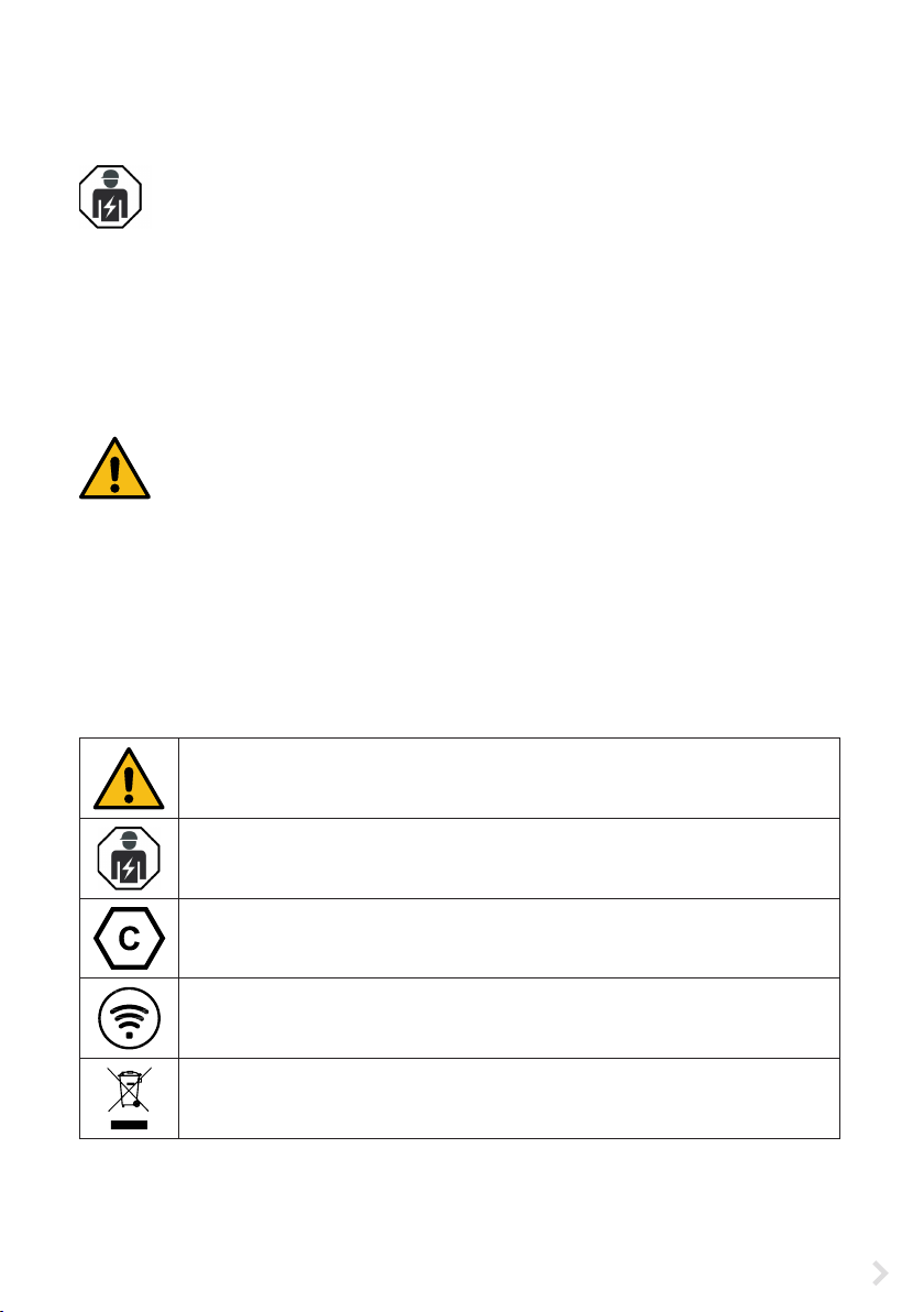
2. Description of symbols
WARNING - Indicates a hazard with a medium level of risk which, if not avoided, could
result in death or serious injury or considerable damage to the equipment.
Electrically skilled person
Identier for plug and socket outlet
AC / EN62196-2 / Type 2
Radio-frequency identication reading area for automatical identifying of RFID tags.
Environmental instructions

RAK111B_EN / 2023-09-14
4 / 32
4. Delivery contents
• Charging station
• Label set with RCBO testing instructions (EVB100B-B4BC)
• Triangular key
• Installation Instructions / User Guide in English,
other languages please see https://evwiki.ensto.technology/
Plastic front cover
3-color LED indicates the
charging point’s status
1-2 x Mode 3/ Type 2
socket outlet
Painted steel frame
RFID reader
Front cover lock
Abbrevia-
tion Description
LED Light Emitting Diode
MCB Miniature Circuit Breaker, protects cables from over load and short circuits
OCPP Open Charge Point Protocol, protocol how the charger communicates with the backend
systems
RCBO Residual current Circuit Breaker with Overcurrent protection
RCD Residual Current Device, protects humans and animals from electric shock
RDC-DD Residual direct current detecting device
RFID Radio Frequency Identication, information remote reading/writing system, here used to
identify authorized charging point users
USB Universal Serial Bus, specications for cables, connectors and protocols
RS-485 Recommended Standard 485, standard dening the characteristics of drivers and receiv-
ers for use in serial communications systems
3. Abbreviations
Type label
Energy meter
(EVB100B...)

RAK111B_EN / 2023-09-14 5 / 32
5. Accessories
Flange KOT21715
Included in the delivery.
Note! Cable glands are not included in the delivery.
Please order suitable cable glands separately according to the used supply cable sizes, for example Ensto
KTM... cable gland series (polyamide or brass).
1-2 x Mode 3/ Type 2
socket outlet
EVTL40.00
Wall bracket
The wall bracket is pre-installed to the charging station.
0.7
216
8
86
+0.1
-0.1
300
2x Ø6
436
240
4x Ø7
320
Ø12.5 (knock-out)
Ø20.5 2pcs (knock-outs)
Ø32.5 2pcs (knock-outs)
All
knock-outs

RAK111B_EN / 2023-09-14
6 / 32
EVTL43.00
Ground / Floor mounting pole
The delivery includes ange F2202.
Flange 2202
200
250
150
4 x Ø14
100
1029,5
(4 x Ø9,5)

RAK111B_EN / 2023-09-14 7 / 32
EVTL44.00
Adapter for ground mounting
Ø60,3
100
150
408 ± 1
Ø54,5
8
4 x M12
200
250

RAK111B_EN / 2023-09-14
8 / 32
6. Mounting instructions
6.1. Before installation
Remove the the charging station from its package. Do not scratch the surface of the the charging station
after removal from the package.
When selecting installation site, take into consideration the following:
• The minimum space necessary for operating and maintenance.
• Make sure that the mounting foundation is applicable and robust.
• To ensure the optimal charging performance, the the charging station should not be exposed to
direct sunlight.
• If the charging station is installed in corrosive conditions where there is a risk of metal rusting, visible
metal surfaces must be protected regularly with anti-corrosion agent.
Obey national regulations and site
requirements
Recommendation
900 - 1200 mm
min. 400 mm
min. 200 mm
RAK111B_EN / 2023-09-14 9 / 32
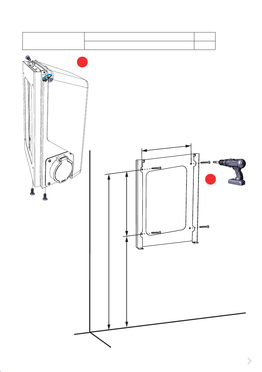
Installation steps
1. Remove the pre-installed wall bracket from the charging
station [1]. Loosen the 2 fastening screws from the top of
the charging station and 2 fastening screws from the bot-
tom.
2. Drill screw holes for the wall bracket [2].
3. Attach the wall bracket to the wall. Select applicable
screws for the wall.
4. Attach the charging station to the wall bracket with the 4
fastening screws you removed in the step 1.
5. See wiring instructions on page 15.
6.2. Wall mounting with wall bracket
Installation accessories Wall bracket EVTL40.00 1 pcs
Screws 4 pcs
1200 320
1520
240
2
1
The socket outlet will be at
a height of 1200 mm

RAK111B_EN / 2023-09-14
10 / 32
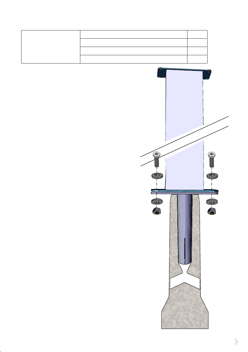
6.3. Ground mounting on concrete casting with ground mounting pole
Installation accessories Ground mounting pole EVTL43.00 1 pcs
Anchor bolts M12 4 pcs
Bolts and nuts (not included)
Make sure that the materials used for the concrete casting and the installation procedures follow local
building regulations and safety standards.
• Dig a trench for cable conduits and an excavation pit for the concrete foundation. The pit oor
should be compacted and level.
• Put cable and possible drain pipes in place.
• Fill the pit with concrete.
• Let the concrete cure. Make sure that the surface stays level during the process.
Installation steps
1. Make sure that the concrete surface is compacted
and level.
2. Drill a hole in the concrete for the anchor bolts. For
more information, please see the anchor bolt instruc-
tions.
3. Put the anchor bolts in place.
4. Pull the electric cables approx. 1500 mm measured from
the concrete surface.
5. Attach the ground mounting pole to the anchor bolts
with washers and nuts.
6. Pull the electrical cables through the ground mounting
pole.
7. Attach the charging station to the mounting pole. See
instructions on page 14.
200
100
RAK111B_EN / 2023-09-14 11 / 32
6.4. Ground mounting on concrete foundation with ground mounting pole
Installation accessories Ground mounting pole EVTL43.00 1 pcs
Adapter for concrete foundation EVTL44.00 1 pcs
Concrete foundation (from dierent manufacturers) 1 pcs
Bolts, washers and nuts (not included)
Installation steps
1. Dig a trench for cable conduits and an excavation pit
for the concrete foundation to applicable depths.
2. Add gravel to the bottom of the pit, to such thickness
that the top of the foundation will be at applicable
level when you lift the foundation into the pit. Take
into consideration the possible paving materials
when you set the level.
3. Lift the concrete foundation into the installation pit.
For more information, please see the concrete foun-
dation mounting instructions.
4. Put cable and possible drain conduits in place.
5. Lift the adapter EVTL44.00 into the concrete founda-
tion. Cut the adapter, if necessary. Adjust the adapter
in such a manner, that the top surface of the adapter
is horizontal. Make sure, that the adapter is securely
in place and does not swing.
6. Pull electric cables through the conduits and the
adapter approx. 1500 mm measured from the adapt-
er ange.
7. Tighten the foundation to its place by lling the ex-
cess space outside the foundation with gravel.
8. Attach the ground mounting pole to the adapter
with bolts, washers and nuts (included).
9. Pull the electrical cables through the ground mount-
ing pole.
10. Attach the charging station to the mounting pole.
See instructions on page 14.
x 4
x 8
x 4

RAK111B_EN / 2023-09-14
12 / 32
6.5. Ground mounting on Unimi concrete foundation
This installation example describes the installation procedure when a concrete foundation supplied by
Unimi - Solutions is used.
Installation accessories Ground mounting pole EVTL43.00 1 pcs (1 x EVB)
2 pcs (2 x EVB)
Installation accessories,
order from www.unimi.se
Concrete foundation 1 pcs
Cover plate 1 pcs
Adapter for 1 x EVB, product code US7650 1 pcs
Adapter for 2 x EVB, product code US27657 1 pcs
Installation steps
1. Dig a trench for cable conduits and an excavation pit for the concrete foundation to applicable
depths. The pit oor should be compacted and level.
2. Adjust the depth of the pit so that the top of the foundation will be ush with the nal surrounding
ground surface. Take into consideration the possible paving materials.
3. Cover the unused conduit openings with plugs, which are included in the foundation delivery.
Note! When using the adapter for two charging stations (US27657), you can get up to four charging outlets.
395
250
Ø15
Ø115 (x4)
450
600
US7650 US27657

RAK111B_EN / 2023-09-14 13 / 32
4. Lift the foundation into the installation pit. You can use the attachment bar in the foundation as a
lifting point. Make sure that the mounting bar is in a direction that enables the installation of the
charging station in correct position.
5. Put cable conduits into the trenches and install the conduits to relevant inlets.
6. Pull electric cables through the conduits into the foundation approx. 1500mm measured from the
top of the foundation.
7. Tighten the foundation to its place by lling the excess space outside the foundation with gravel.
8. Set the nal layer of gravel so that the top of the foundation will be ush with ground or the nal
paving material.
9. Always put a cover plate on the foundation, if the charging station is installed in a separate session
than the foundation.
10. Remove the cover plate before you start the installation work.
11. Put the adapter element on the foundation.
12. Attach the adapter element to the foundation at-
tachment bar with bolts 3 pcs (included).
13. Put the mounting pole on the adapter. Tighten with
the washers and nuts included in the delivery.
14. Pull the electrical cables through the mounting pole.
15. Attach the charging station to the mounting pole.
See instructions on page 14.
RAK111B_EN / 2023-09-14
14 / 32
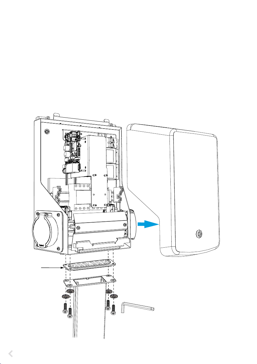
6.6. Attaching charging station to mounting pole EVTL43.00
Installation steps
1. Open the front cover lock and remove the front cover.
2. Remove the ange at the bottom of the charging station frame. Use the multigate gland plate F2202
(included in the mounting pole delivery) to make sure that the ingress protection rating will be suf-
cient.
3. Pull the electrical cables through the applicable glands of the F2202.
4. Attach the charging station and the gland plate F2202 to the mounting pole with the screws you
removed in the step 2.
F2202
8 mm

RAK111B_EN / 2023-09-14 15 / 32
7. Electrical connections
7.1. Wiring instructions
1. Open the front cover lock and remove the front cover.
2. Remove the plastic shield.
3. You can remove the steel bracket on the front, if it is necessary to get more space during the instal-
lation work.
4. Remove the cable sheath approx. 150 mm.
5. Pull the supply cable through the cable gland approx. 200mm measured from the cable gland.
6. Cut the supply cable conductors to applicable lengths. The earth conductor must be long enough,
so that if a fault occurs it is the last one that comes loose.
7. Strip the conductors 10 - 12 mm and connect to the supply connectors.
8. Attach the steel bracket in place.
9. Attach the plastic shield to correct position.
10. Close the front cover.
10-12 mm
Supply connectors
Plastic shield
Steel bracket

RAK111B_EN / 2023-09-14
16 / 32
7.2. Power supply
The voltage and current ratings including cables and line protector dimensioning must comply with na-
tional regulations. System dimensioning must be done by a qualied electrical designer.
Connect separate supply cables for each charging outlet.
We recommend supply cables with stranded conductors.
Supply connection to charging station with one outlet
EVB100B-B4BC
• A combined device with residual current circuit breaker and over current protection (RCBO) is inte-
grated in the charging station.
• A label set of RCBO testing instructions is included in the delivery. Attach a language specic label on
the charging station on a position where it can be seen.
EVB100B-A4BC
• A Residual current protection device (RCD type A, 30mA) and a circuit breaker (MCB max. 32A) for
each charging outlet must be installed in the switchboard.
NL3L2L1 PE
NL3L2L1 PE
TN network
Supply
Cu 2.5 - 16 mm²
L2L1 PE
NL3L2L1 PE
IT network
Supply
Cu 2.5 - 16 mm²
If you connect the charging station to an IT network, you must set the energy meter
to 2-phase mode from the energy meter settings.
L1 L2 L3 N PE L1 L2 PE
Sealing
Plastic
window
Sealing
Energy meter
Steel
plate
TX25
RAK111B_EN / 2023-09-14 17 / 32
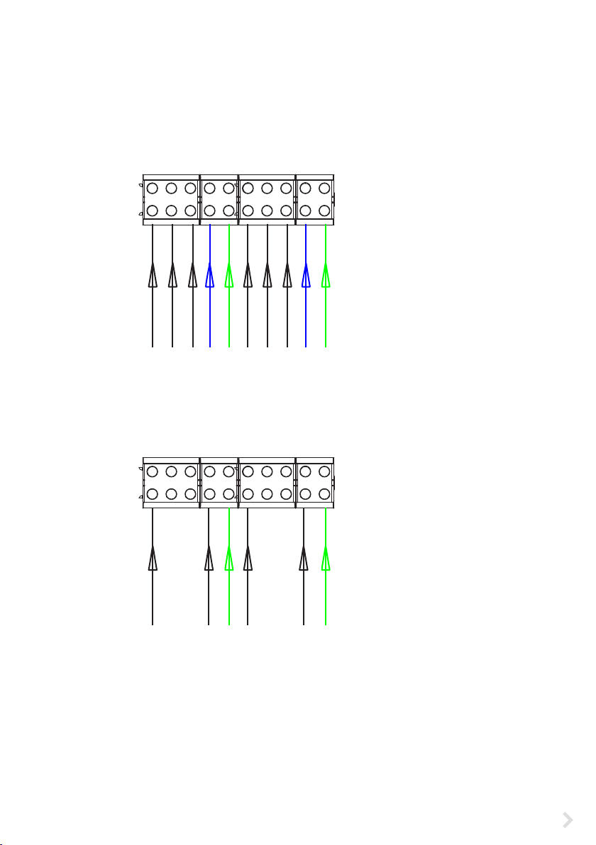
EVB200B-A4BC
• A Residual current protection device (RCD type A, 30mA) and a circuit breaker (MCB max. 32A) for
each charging outlet must be installed in the switchboard.
Note! Phase rotation inside the charging station is not allowed.
TN network
Supply 1
Cu 2.5 - 16 mm²
NL3L2L1 PE NL3L2L1 PE
NL3L2L1 PE NL3L2L1 PE
Supply 2
Cu 2.5 - 16 mm²
Supply connection to charging station with two outlets
IT network
Supply 1
Cu 2.5 - 16 mm²
L2L1 PE L2L1 PE
NL3L2L1 PE NL3L2L1 PE
Supply 2
Cu 2.5 - 16 mm²
If you connect the charging station to an IT network, you must set the
energy meters to 2-phase mode from the energy meter settings.
Remove the front cover of the charging station.
The energy meters are installed on the right side.
L1 L2 L3 N PE L1 L2 L3 N PE
L1 L2 PE L1 L2 PE
L1 L2 PE
RAK111B_EN / 2023-09-14
18 / 32
8. Commissioning
Before commissioning the charging station must be installed according to the installation instructions.
By default all charging stations are operating in free charging mode (standalone operation). In this free
charging mode external communication (Ethernet, 4G, LAN orWiFi) is not active. If you connect the charg-
ing station to some back-oce (online mode), rst make sure that the basic functionality is working be-
fore establishing communication.
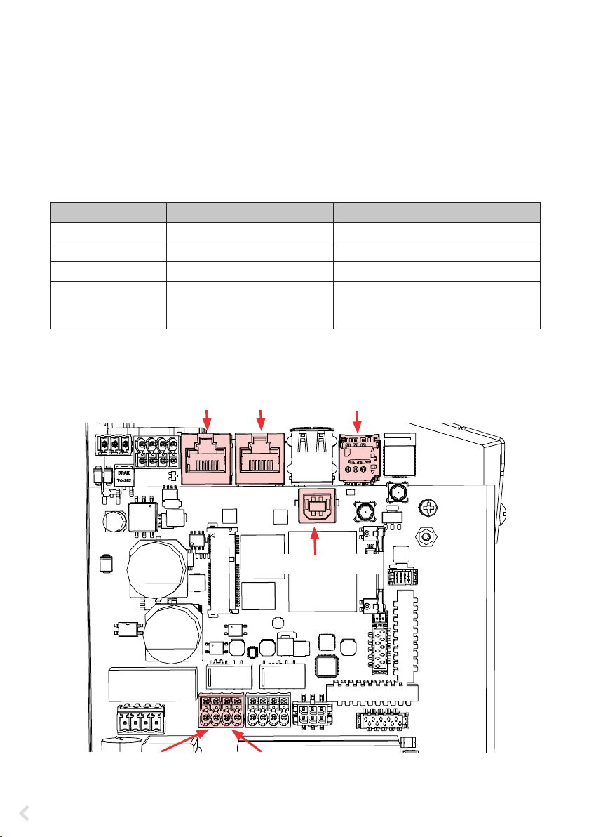
8.1. View of the component layout on the control unit
Component Connection Note
USB B Service port Computer to the charging station EVB200: Connect to the right side
Ethernet 1 / 2 Ethernet communication cable EVB200: Connect input to the left side
Micro SIM card holder Connection to mobile network EVB200: The holder is on the left side
Optocoupler input
(+ / - 12V)
Control of charging event via
external device / input
External input operation must be cong-
ured on charging station settings. Please
ask your Ensto representative for details.
EVB100...
USB B service port
Micro SIM card holder
Ethernet 1Ethernet 2
Opto1- / Opto1+
Optocoupler input 12V
Opto2- / Opto2+
Optocoupler input 12V
EVB200... control unit on the left side

RAK111B_EN / 2023-09-14 19 / 32
8.2. Connecting to the charging station
If you want to change the default settings, you must connect to the charging station via web congura-
tion tool to be able to start congure the commissioning settings. Use Firefox, Chrome or Windows Edge
web-browser for conguring.
USB B
Connect to the
charging station
USB A
Connect to the
computer
EVB200... control unit on the right side
Ethernet 1 Ethernet 2
USB B service port
Opto1- / Opto1+
Optocoupler input 12V
Opto2- / Opto2+
Optocoupler input 12V

RAK111B_EN / 2023-09-14
20 / 32
8.4. WiFi coverage area
If you want to use a WiFi network, rst do a WiFi survey to make sure that the network works correctly. The
survey helps you to identify potential issues and optimize coverage.
General steps how to do a WiFi survey
1. Plan the survey.
Dene the purpose of the survey: estimate coverage, identify dead spots, optimize performance etc.
Dene the survey areas, including indoor and outdoor spaces.
2. Collect necessary tools.
Get a WiFi survey tool or software. There are various free and commercial options available, such as
Ekahau, NetSpot and Acrylic Wi-Fi Home.
3. Prepare the survey environment.
Make sure that the WiFi network is working. Make sure that in the survey area are not any objects or
interference sources that may aect signal propagation, such as large metal objects or other elec-
tronic devices.
Chaining the Ethernet connections is allowed.
EVB200: Connect the Ethernet input to the ETH1 connector on the left side control unit.
Charging station 1 Charging station 2 Charging station 3
8.3. Ethernet connections
ETH 1 ETH 2 ETH 1 ETH 2 ETH 1 ETH 2
IN
EVB...
Examine the available signal strength
to make sure that the communication
(4G, WiFi), reception and connectivity
are working.
max. 10 m in free space
Other manuals for Wallbox
1
Table of contents
Other ensto Batteries Charger manuals

ensto
ensto EVH-ACRM0 Series User manual

ensto
ensto EVB203E Series User manual

ensto
ensto EVF100 User manual

ensto
ensto EVB200EB-B4BC User manual

ensto
ensto One Home EVH161-HC000 User manual

ensto
ensto One Apartment EVH161-ACRM0 User manual

ensto
ensto One Home User manual

ensto
ensto Pro EVF200 Wiring diagram

ensto
ensto One Home EVH161B-HC000 User manual

ensto
ensto EVB100 User manual


