7
IP2070 - 2012-10-30
ADVERTENCIAS GENERALES DE SEGURIDAD
El presente manual de instalaciòn està destinado exclusi-
vamente a profesionales calificados. Leer atentamente las
instrucciones antes de comenzar la instalciòn del producto. El
material de embalaje (plàstico, poliestirol, etc) debe desechar-
se sin causar daño al medio ambiente y mantenerse fuera del
alcance de los niños, porque es una potencial fuente de peligro.
Antes de comenzar la instalaciòn. verificar que el producto estè
integro. Para cualquier reparaciòn o sustituciòn del producto,
utilizar exclusivamente repuestos originales. Verificar perió-
dicamente el buen funcionamiento del desbloqueo manual.
1. DESCRIPCIÓN
Bloque de seguridad con desbloqueo manual para
automatizaciónes VALORHL y VALORHS.
2. DATOS TÉCNICOS
Descripcion VALHLLOK-VALHSLOK
Alimentaciòn 24 V
Absorción max 1 A
Carrera pistòn 10 mm
Temperatura min -20 °C max +55 °C
3. REFERENCIAS
[1] Electroimán de desbloqueo
[2] Estribo de enganche bloque
[3] Manija de desbloqueo
[4] Regulador de tensión hilo
[5] Funda (máx 5 m)
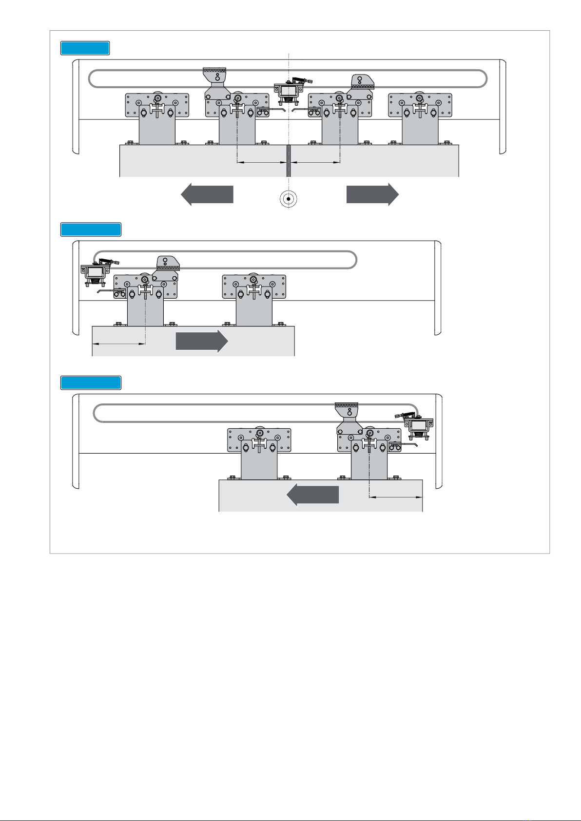
4. INSTALACIÒN
ǩ )LMHPHGLDQWHORVWRUQLOORVVXPLQLVWUDGRVHOEORTXHDOSHUȌO
de la caja, como indicado en la fig. 1.
ǩ 'HVSODFHODKRMDHQFLHUUH\UHJXOHODSRVLFLµQGHOEORTXH
de manera que se obtenga el enganche correcto con el
estribo de enganche bloque [2]. Las pequeñas correcciones
de posición se realizan utilizando el ranurado del estribo
de enganche bloque [2]; las correcciones más importantes
se realizan desplazando el bloque.
Para la conexión de la manija de desbloqueo LOKSBM [3],
consulte el manual de instalación correspondiente.
Accione la manija de desbloqueo LOKSBM [3] y regule la tensión
de la cuerda, utilizando el regulador de tensión hilo [4], de mane-
raquese obtenga el correctoenganche/desenganchedelbloque.
ATENCIÓN: la funda [5] no debe realizar curvas estrechas. La
manija de desbloqueo LOKSBM [3] debe estar fijado siempre
en un lugar visible y accesible.
5. AUTOMATISMOS CON APERTURA A LA DERECHA
Para instalar el dispositivo de bloqueo en automatismos con
apertura a la derecha, opere como indicado en la fig. 3:
ǩ GHVHQURVTXHHOWRUQLOOR>@\TXLWHHOPHFDQLVPRGHGHVEOR-
TXHR>@
ǩ GHVHQURVTXHHOWRUQLOOR>@\GHVSO£FHORKDFLDHORWURRULȌFLR
ǩ JLUHHOPHFDQLVPRGHGHVEORTXHR>@HQr\I¯MHORHQHO
EORTXHFRQHOWRUQLOOR>@
6. CONEXIONES ELÉCTRICAS
Conectar los bornes del dispositivo de bloqueo a los bornes LK
del cuadro electrónico con la ayuda del cable suministrado.
Para mayores informaciones, consulte el manual de instalación
del cuadro electrónico.
ATENCIÓN: corte el cable sobrante y bloquéelo mediante el
sujeta-cables que le suministramos junto con el automatismo.
Configurar DIP1=OFF en cuadro electrónico.
ADVERTÊNCIAS GERAIS PARA A SEGURANÇA
O presente manual de instalação é dirigido exclusiva-
mente a profissionais especializados. Ler atentamente
as instruções antes de iniciar a instalação do produto. Os
materiais de embalagem (plástico, polistireno, etc.) não devem
ser depositados no ambiente e não devem estar ao alcance das
crianças pois são potenciais fontes de perigo. Antes de iniciar a
instalação verificar a integridade do produto. Para eventual re-
paração ou substituição dos produtos é obrigatório a utilização
GHSH©DVH[FOXVLYDPHQWHJHQX¯QDV9HULȌFDUSHULRGLFDPHQWHR
funcionamento correcto do desbloqueio manual.
1. DESCRIÇÃO
Blocco di sicurezza anti intrusione con sblocco manuale per
automazioni VALORHL e VALORHS.
2. DADOS TÉCNICOS
Descriçao VALHLLOK-VALHSLOK
Alimentação 24 V
Absorção max 1 A
Curso do pistão 10 mm
Temperatura min -20 °C max +55 °C
3. REFERÊNCIAS
[1] Eletromagnético de desbloqueio
[2] Estribo de engate do bloco
[3] Selector de desbloqueio
[4] Registo de tensão do fio
[5] Revestimento (max. 5 m)
4. INSTALAÇÃO
ǩ 0HGLDQWHRVSDUDIXVRVIRUQHFLGRVȌ[DUREORFRQRSHUȌOGR
contentor, conforme indicado na fig. 1.
ǩ 'HVORFDUODIROKDHPIHFKRHDMXVWDUDSRVL©¥RGREORFRSDUD
que fique correctamente encaixado no estribo de engate
do bloco [2]. Pequenos ajustes de posição podem ser feitos
graças às ranhuras do estribo de engate do bloco [2]; para
realizar ajustes mais relevantes, deslocar o bloco.
Para a ligação da manivela de desbloqueio LOKSBM [3], ver os
manuais relativos à instalação.
Accionar a manivela de desbloqueio LOKSBM [3] e ajustar a
tensão da corda, afinando o registo de tensão do fio [4], de modo
a obter o correcto engate/desengate do bloco.
ATENÇÃO: o revestimento [5] não deve efectuar curvas estrei-
tas. A manivela de desbloqueio LOKSBM [3] deve ser sempre
Ȍ[DGDQXPOXJDUYLV¯YHOHDFHVV¯YHO
5. AUTOMATISMOS COM ABERTURA A DIREITA
Para instalar o dispositivo de bloco em automatismos com
abertura à direita, operar da seguinte forma:
ǩ GHVDSDUDIXVDURSDUDIXVR>@HUHWLUDURPHFDQLVPRGH
GHVEORTXHLR>@
ǩ GHVDSDUDIXVDURSDUDIXVR>@HGHVORF£ORSDUDRRXWUR
RULI¯FLR
ǩ JLUDU|RPHFDQLVPRGHGHVEORTXHLR>@HȌ[£ORQREORFR
FRPRSDUDIXVR>@
6. LIGAÇÕES ELÉCTRICAS
Ligar os bornes do bloqueador aos bornes LK do quadro elec-
trónico, utilizando o cabo fornecido.
Para obter mais informações, consultar o manual de instalação
do quadro electrónico.
ATENÇÃO: cortar a parte do cabo que sobrar e bloquear o cabo
mediante os prensa cabos fornecidos com o automatismo.
Configurar DIP1=OFF em quadro electrónico.
Todos los derechos son reservados.
Los datos que se indican han sido redactados y controlados con la
màxima atenciòn. Sin embargo no podemos asumir ninguna respon-
sabilidad por eventuales errores, omisiones o aproximaciones debidas
a exigencias técnicas o gràficas.
Todos os direitos são reservados.
Os dados indicados foram redigidos e controlados com o máximo
cuidado. Contudo, não podemos assumir qualquer responsabilidade
por eventuais erros, omissões ou aproximações devidas a exigências
técnicas ou gráficas.
ESPAÑOL
32578*86