envea HYCONTROL SHIELD Lite User manual
Shieldlite20 Quick Start guide EN V1_2.docx 1 of 4 June 2023
Quick Start Guide
For first time users, we recommend the use of the SPS-Shieldlite system manual
SPS-SHIELDLITE SYSTEM
2. PARTS LIST
Failure to follow safe operating / installation and maintenance guidelines could result in serious injury or death
➢Use suitable PPE for tasks to be performed and for the environment you are working in.
➢All installation, operation and maintenance work must be undertaken by qualified authorised personnel.
➢All applicable industry and statutory regulations must be followed.
➢Any site-specific equipment should be used.
➢Ensure all tools are in good working order.
➢DO NOT undertake any operation or work on the PRV on the silo top unless qualified and authorised to do
so.
➢For full manual, refer to https://www.hycontrol.com/downloads/manuals.
The product described in this document is NOT suitable for use in an ATEX classified area.
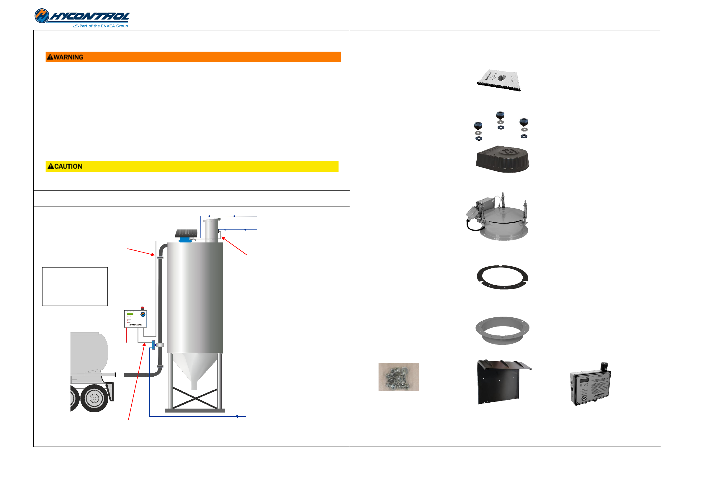
1. SYSTEM OVERVIEW
WEATHER COVER
PRESSURE RELIEF VALVE
UPSTAND /
SPIGOT FLANGE
SPS-SHIELDLITEDB
INSTRUCTION MANUAL
3x METAL PENNY WASHERS
3x RUBBER WASHERS
3x HAND KNOBS
GASKET
9 x M10 30mm
BOLTS &
WASHERS
WEATHER COVER FOR
SPS-SHIELDLITEDB
PRESSURE SENSOR
LEVEL PROBE
Filter control
3 core screened cable
Inlet fill valve
6 core screened cable
(control and feedback)
24V DC and comms
4 core screened cable
(Maximum 100m length)
AIR SUPPLY TO
FILL VALVE
6 –8 bar (87 - 116psi)
100 –240V
AC Supply
CONTINUOUS AIR SUPPLY TO PRV
7 –10 bar (101 –145psi)
AIR SUPPLY TO FILTER
DISPLAY PANEL
MUST BE MOUNTED
AT FILL POINT
VISIBLE TO DRIVER
Shieldlite20 Quick Start guide EN V1_2.docx 2 of 4 June 2023
Quick Start Guide
3. INSTALLATION
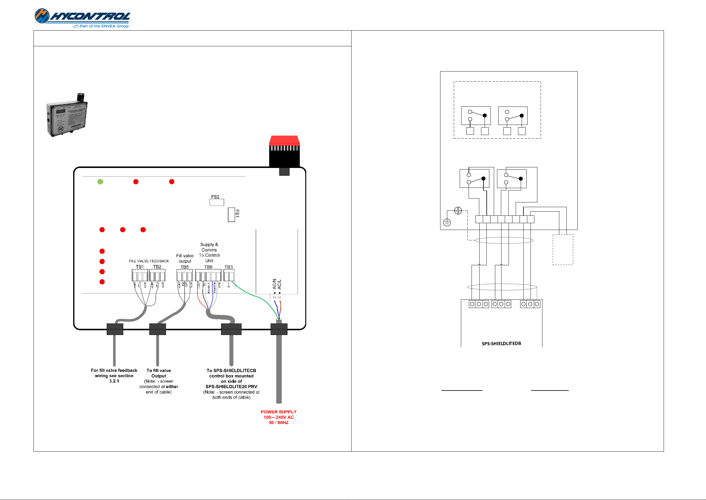
3.2 WIRING THE FILL VALVE
3.2.1 Wiring to a fill valve with open / close position switch feedback
Fill O/P
+24V
I/P 2
+24V
+24V
I/P 1
Scr
TB1 TB2 TB5
FILL VALVE FEEDBACK Fill valve
output
GROUND
Optional
connection
to cable
screen at
switch box
Scr
Scr
8
7
6
5
4
3
2
1
TOP
SWITCH
(SW1)
BOTTOM
SWITCH
(SW2)
Fill valve switch position feedback
Fill valve switch box
Connection
to cable
screen at
instrument
NO COM
NC
NO COM
NC
FILL VALVE
SOLENOID
NC
COM
NO
NO COM
NC
TOP
SWITCH
(SW1)
BOTTOM
SWITCH
(SW2)
2
15
4
Switch positions - valve CLOSED
Switch positions - valve OPEN
Expected voltages
Fill valve closed Fill valve open
24V DC on I/P 1 0V DC on I/P 1
0V DC on I/P 2 24V DC on I/P 2
Note: - All voltages measured with respect to Terminal TB5 Scr on SPS-SHIELDLITEDB PCB.
TB1, TB2 and TB5 connections can share the same cable requiring only one screen connection at the display panel
end. If separate cables are used, each cable must have its own screen connection e.g. TB1 Scr, TB2 Scr and TB5 Scr.
3.1. MOUNTING THE DISPLAY UNIT
3.1.1 Wiring the SPS-SHIELDLITEDB display panel
Display panel mounting considerations
•DISPLAY PANEL MUST BE MOUNTED AT FILL POINT VISIBLE TO DRIVER.
•Power from an isolatable power supply.
•Mount at head height so easily viewable and within comfortable reach.
•Protect from the elements –use weather cover supplied.
Figure 1: - Wiring SPS-SHIELDLITEDB display panel
Figure 2: - Fill valve switch box wiring

Shieldlite20 Quick Start guide EN V1_2.docx 3 of 4 June 2023
Quick Start Guide
3.3 PRV MOUNTING CONSIDERATIONS
When positioning the spigot allow for a 40” (1.0m) diameter footprint free of any obstructions for correct
positioning, wiring and removal of covers. Be aware of the following points:-
•
•DO NOT mount probe in fill path of the material as this
will cause premature wear and failure.
•Ensure there is sufficient space to remove and install
probes for maintenance.
•DO NOT install in front of ladder access.
•We recommend removal of old PRVs to prevent false
venting.
•Mount as close to filter as possible but not in way of fill.
•Beware of internal fill pipes, ladders, split silos etc.
We recommend cutting the main access hole after welding
on the spigot.
3.4 REMOVING THE HIGH LEVEL PROBE FROM UNDERSIDE OF PRV
The high level probe of the SPS-SHIELDLITE20 system comes pre-fitted on the side of the PRV and already wired to
the PRV control box. Ensure to remove the level probe sensor from the underside of the PRV prior to installation by
cutting the 3 cable ties and removing the plastic tip protector.
3.5 WIRING THE SPS-SHIELDLITECB PRV CONTROL BOX
WARNING! NEVER APPLY AC MAINS VOLTAGE TO CONTROL BOX.
Remove cover of control box and wire the following cables to the control box’s PCB using the glands as shown in
Figure 8: -
1) Wire 4-core screened supply and communications cable from the
SPS-SHIELDLITEDB display panel TB8 to control box TB11.
2) Wire 3-core screened cable between control box TB3 and Hycontrol
HYVENT silo filter - see section 3.6.1.
The control box wiring is now complete.
Figure 6: - DP probe
mounting
1.1
Figure 7: - Control box located
on the side of the PRV
Figure 8: - SPS-SHIELDLITECB terminal wiring
Figure 5: - Shows level probe sensor
underside of PRV secured by 3 cable
ties and with tip protector
Figure 4: - Shows level probe mounted
on side of PRV
Figure 3: - Ideal location of PRV on silo top

Shieldlite20 Quick Start guide EN V1_2.docx 4 of 4 June 2023
Quick Start Guide
Output type
Filter output
24V
On/
Off
0V
HYVENT 24V
DC FILTER
CONTROLLER
SPS-SHIELDLITECB
TB3
LINK
13 14 15
1234512
L N PE
Output type
Filter output
1
24V
On/
Off
0V
2
WAM SILOTOP
Zero / R03 filter
SPS-SHIELDLITECB
TB3
3
4
LINK
S1
S2
3.6 WIRING THE ANCILLARIES
3.7 CONNECTING THE AIR-LINE
Connect the air-line into the pressure regulator as shown in Figure 11 and
check pressure on gauge is at 6 bar.
Note: - The air supply MUST be clean and dry and filtered to 25 microns.
4. COMMISSIONING
After completing the mechanical, electrical and pneumatic installation perform the following checks: -
Pre commissioning checks
1. Air pressure regulator on the SPS-SHIELDLITE PRV should be set at 6.0 bar (87psi).
2. Air pressure at the fill valve should be at least a constant 6 bar (87psi). Consider other demands on the
air supply which might affect this.
3. Confirm the specified AC voltage to the display panel (100V –240V AC 50Hz/60Hz).
4. Confirm the 24VDC output from the display panel at TB8 between pins 0V and +24V.
See section 3.1.1 for connector location.
Commissioning checks
5. At start-up, ensure the display shows the “SPS SHIELD LITE GLT key to start” screen.
6. Switch the GLT key-switch clockwise and release. If the initial check passes then the beacon and siren will flash
for five seconds during the test.
7. If the test is successful, the display will show “Safe to fill 90 min remaining”, the fill valve will open and a
delivery can commence.
8. If the test fails, a message will be displayed and the fill valve will remain closed. At this point further
investigation is required as to the cause of the test failure. See Trouble shooting section of full manual for
further details.
5. FURTHER INFORMATION
Hycontrol provides complete documentation and instructional videos for installing, commissioning, and operating
the SHIELD Lite system. Rather than multiple manuals for different components, SHIELD Lite requires only one.
All these resources are available through Hycontrol’s specialist website, www.siloprotection.com.
3.6.1 Wiring the 24V DC HYVENT silo filter
Table 1: - Hyvent program
3.6.1.1 24V DC Hycontrol Hyvent filter connection using external ON/OFF control
Connect TB3 as in diagram below. Link pins 12 to 13 on Hyvent 24V DC Filter controller.
Figure 9: - Wiring to a 24V DC powered Hycontrol Hyvent silo filter
3.6.2 WAM SiloTop zero / R03 filter connection
Connect TB3 as in diagram below. Link pins 3 to 4 on WAM silo. The filter should be set to sequence automatically
on power up.
Figure 10: - Wiring to a WAM SILOTOP zero / R03 filter
Controller program
Parameter
Setting
F01
0
F02
0.5
F03
30
F04
3
F05
0
F06
1
F07
1
F08
24
Figure 11: - Connecting the air-line
Other envea Industrial Equipment manuals


