Envent 330S-Ex User manual

Envent Engineering Ltd.
Hydrogen Sulfide Analyzer
Model 330S-Ex
Model 330SDS-Ex
User's Manual
Revision 1
21 Jan 2022


Table of Contents
INTRODUCTION ................................................................................................................................... 1
Contacting Envent Engineering Ltd .................................................................................................... 1
Canada Office: (Main)..................................................................................................................... 1
USA Office:..................................................................................................................................... 1
China Office:................................................................................................................................... 1
Warranty & Liability Statements ......................................................................................................... 2
Limitation of Warranty..................................................................................................................... 2
Disclaimer .......................................................................................................................................... 2
Key Symbols ...................................................................................................................................... 3
Warnings & Cautions.......................................................................................................................... 3
Warning & Cautions for 330S-Ex & 330SDS-Ex H2S Analyzers ...................................................... 3
Analyzer Specifications ...................................................................................................................... 6
PRINCIPLE OF OPERATION................................................................................................................ 7
Physical Reaction............................................................................................................................... 7
Analysis Cycles .................................................................................................................................. 8
Dual Sensor Analysis cycle (SDS): ............................................................................................... 10
INSTALLATION .................................................................................................................................. 11
Receiving the Analyzer..................................................................................................................... 11
Unpacking the Analyzer................................................................................................................ 11
Standard spare parts for 330S-Ex H2S analyzers: ........................................................................ 11
Installation procedure & Start-up ...................................................................................................... 12
Installation Requirements................................................................................................................. 13
Electrical Requirements ................................................................................................................ 13
Location for the System ................................................................................................................ 13
Earth Connections, Entry Specifications & Space Requirements .................................................. 14
Sample Point Selection................................................................................................................. 21
Sample inlet & sample sweep ....................................................................................................... 21
Vent line ....................................................................................................................................... 21
Sample Volume & Flow Rate ........................................................................................................ 22
Installation of Analyzer Components ................................................................................................ 23
Analog Outputs............................................................................................................................. 23
Sample Chamber.......................................................................................................................... 24
Humidifier Unit .............................................................................................................................. 26
Eductor Block ............................................................................................................................... 28
OPERATION & CONFIGURATION ..................................................................................................... 30
Analyzer Display Interface................................................................................................................ 30
CALIBRATION PROCEDURES .......................................................................................................... 32

H2S Gas Calibration ......................................................................................................................... 32
Re-zero Sensor Procedure............................................................................................................... 33
MAINTENANCE .................................................................................................................................. 35
H2S Sensing Tape Change Procedure ............................................................................................. 35
Sample Conditioning System Cleaning Procedure ........................................................................... 36
Material List .................................................................................................................................. 36
Procedure..................................................................................................................................... 36
TROUBLESHOOTING ........................................................................................................................ 38
APPENDICES ..................................................................................................................................... 48
Recommended Spare Parts List....................................................................................................... 48
Sealing Compound: For sealing fittings in Hazardous Locations ...................................................... 49
Safety Data Sheet for H2S Sensing Tape ......................................................................................... 61

List of Figures
Figure 1. H2S Analyzer Principle of Operation Diagram ......................................................................... 8
Figure 2. H2S Analysis Cycle ................................................................................................................. 9
Figure 3. Enclosure Entries & Earth Connections ................................................................................ 14
Figure 4. Space Requirements & Entry Specifications for Model 330S-Ex (No Backpan) .................... 15
Figure 5. Space Requirements & Entry Specifications for Model 330SDS-Ex (No Backpan) ............... 16
Figure 6. Space Requirements for 330S-Ex with Standard Backpan (Size may vary) .......................... 17
Figure 7. Space Requirements for 330SDS-Ex with Standard Backpan (Size may vary) ..................... 18
Figure 8. Space Requirements for 330S-Ex with Total Sulfur Option (Backpan size may vary)............ 19
Figure 9. Space Requirements for 330SDS-Ex with Total Sulfur Option (Backpan size may vary)....... 20
Figure 10. Recommended Venting for 330S-Ex (Same as the 330SDS-Ex H2S Analyzer)................... 22
Figure 11. AO 4-20 mA Output Wiring Options .................................................................................... 24
Figure 12. Sample Chamber (Exploded View) ..................................................................................... 25
Figure 13. Envent's Humidifier Unit for 330S-Ex & 330SDS................................................................. 27
Figure 14. Humidifier Unit Installed in a 330S-Ex H2S Analyzer ........................................................... 28
Figure 15. Eductor Block (Venturi Effect) ............................................................................................. 28
Figure 16. 330S-Ex or 330SDS-Ex Display.......................................................................................... 30
Figure 17. 330S-Ex & 33SDS-Ex H2S Sensing Tape Change Procedure............................................. 35
List of Tables
Table 1. 330S-Ex 330SDS-Ex H2S Analyzer Specifications .................................................................. 6
Table 2. Sample Volume and & Flow Rate........................................................................................... 22
Table 3. Aperture Strips & Ranges ...................................................................................................... 26
Table 4. Display Button Description/Function....................................................................................... 30
Table 5. Display LED Description/Function .......................................................................................... 31

Envent Engineering Ltd. Page 1 Revision 1
INTRODUCTION
This manual provides all the necessary information to install, operate and
maintain the 330S-Ex and 330SDS-Ex model H2S Analyzer units. This manual is
intended for all technical level users.
The Envent 330S-Ex and 330SDS-Ex H2S Analyzer is a uniquely rugged and
simple design that utilizes lead acetate-based detection which provides a linear
and interference-free output of H2S concentration. This analyzer can measure a
wide range of hydrogen sulfide concentrations from parts per billion (ppb)
concentrations to parts per million (ppm) concentrations. With the addition of a
dilution sample system, it can read high concentrations in percentage up to
100%. There are other options available such as the sample system for H2S
analysis in liquids or the addition of a hydrogen reaction furnace for total sulfur
measurements.
Throughout this document will be referring to the models 330S-Ex. However, the
information applies equally to the 330SDS-Ex (Dual sensor), unless otherwise
stated. To clarify, the difference between an "S" model and a "SDS" model
analyzer is the second sensor the "SDS" has to measure H2S giving it the
capability to measure H2S from two different samples at the same time.
Contacting Envent Engineering Ltd
This manual covers most of the important information the user is going to need to
install, operate and maintain the 330S-Ex & 330SDS-Ex Analyzers. If more
information is required, you can contact us at:
Canada Office: (Main)
Toll Free: 1 (877) 936 - 8368
Tel: (403) 253 - 4012
Fax: (403) 253 - 4016
Email: info@envent-eng.com
Hours of operation: Monday to Friday – From 8:00 am to 4:30 pm (Mountain
Time Zone). Offices closed on statutory holidays.
USA Office:
Tel: 1 (713) 567 - 4421
China Office:
Tel: (86) 138 - 0119 - 1148
For further information on our products and most updated manuals/product
catalog please visit: www.envent-eng.com

Envent Engineering Ltd. Page 2 Revision 1
Warranty & Liability Statements
Products manufactured and supplied by Envent Engineering Ltd unless
otherwise stated are warranted against defects in materials and workmanship for
up to 18 months from the date of shipment or 12 months from date of start-up,
whichever occurs first. During the warranty period the manufacturer will, as its
option, either repair or replace products, which prove to be defective.
The manufacturer or its representative can provide warranty service at the
buyer's facility only upon prior agreement. In all cases the buyer has the option of
returning the product for warranty service to a facility designated by the
manufacturer or its representatives. The buyer shall prepay shipping charges for
products returned to a service facility, and the manufacturer or its representatives
shall pay for return of the products to the buyer. The buyer may also be required
to pay round-trip travel expenses and labour charges at prevailing labour rates if
warranty is disqualified for reasons listed below.
Limitation of Warranty
The foregoing warranty shall not apply to defects arising from:
•Improper or inadequate maintenance by the user;
•Improper or inadequate unpacking or site preparation/installation;
•Unauthorized modification or misuse;
•Operation of the product in unfavorable environments, especially high
temperature and/or high humidity;
•Corrosive or other damaging atmospheres or otherwise outside
published specifications of analyzer.
Envent Engineering Ltd carries no responsibility for damage cause by
transportation or unpacking, unless otherwise specified in the incoterms.
Extended warranty may be available with certified start-up. Contact Envent
Engineering Ltd for details.
Envent Engineering Ltd reserves the right to change the product design and
specifications at any time without prior notice.
Disclaimer
No other warranty is expressed or implied. The manufacturer specially disclaims
the implied warranties of merchantability and fitness for a particular purpose.
The sole remedy of the buyer shall in no case exceed the purchase price of the
analyzer.
The manufacturer shall not be liable for personal injury or property damage
suffered in servicing the product. The product should not be modified or repaired
in a manner at variance with procedures established by the manufacturer.

Envent Engineering Ltd. Page 3 Revision 1
Envent Engineering Ltd is not resposable for the proper disposal of the H2S
sensing tape which contains lead acetate. It is the responsibility of the end user to
properly dispose the tape according to their local or national regulations. Envent
Engineering offers to take back used H2S sensing tape for its proper disposal if
needed, please contact us if this service is required. For more information on the
H2S sensing tape, please refer to "Safety Data Sheet for H2S Sensing Tape" on
page 61.
Key Symbols
The following symbols are used throughout this manual. They are intended to
draw attention to important information.
Description of hazards that could result in major injury or death.
Description of hazards that could result in minor injury or property damage.
Description of important information regarding safety of personal and/or property.
Caution: hot surface.
Description of useful information to help understand a concept.
Warnings & Cautions
This section covers all warnings and cautions for the 330S-Ex and 330SDS-Ex
H2S analyzers. Please read and understand all statements as they are for your
own safety when installing, operating and maintaining the analyzer(s). Some of
these statements are also noted throughout the manual when relevant.
Warning & Cautions for 330S-Ex & 330SDS-Ex H2S Analyzers
Do not disconnect equipment unless power has been switched off or area is
known to be non-hazardous.
Turn off power before servicing. Ensure breakers are off before connecting or
disconnecting power supply.

Envent Engineering Ltd. Page 4 Revision 1
Incorrect configuration of the analyzer may cause incorrect operation. Injury
and/or damage to facilities may occur. Check analyzer's functionality after
configuration changes have been made.
Substitution of components may impair intrinsic safety and suitability for Class I,
zone 1.
Electrostatic Hazard – Backpan and Certification nameplate must be cleaned
only with a damp cloth to prevent static charging hazard.
The analyzer should be mounted in an area in which it is not exposed to
vibration, excessive pressure, temperature and/or environmental variations.
Disassembly of the pressure regulator and solenoids in the field is not advised.
Consult Envent Engineering Ltd if the regulator or solenoid appears
contaminated.
Before resuming line pressure, be sure that all port connections, sample sweep
and sample conditioning system are securely installed.
All connections must be leaktight to ensure the effectiveness of the analyzer as
well as safety. The user is solely responsible for the product selection, safety and
warning requirements for the application. If the equipment is used in a manner
not specified by Envent Engineering Ltd, the protection provided by the
equipment may be impaired.
Do not use solvents, brake cleaners, soaps, detergents or rubbing alcohol to
clean up analyzer or sample system.
This unit may require a disconnect device rated 24 VDC and 5A max. It must be
protected by a circuit breaker rated 24 VDC and 5A max, and it is to be installed
in accordance with local electrical codes.
This unit may require a disconnect device rated 240 VDC and 5A max. It must be
protected by a circuit breaker rated 240 VDC and 5A max, and it is to be installed
in accordance with local electrical codes.
Envent Engineering H2S Sensing Tapes are suitable for use, if stored in the
original sealed package, for 10 years fron date of manufacture. Tapes should be
stored in a coll dry location. If the seal on the package has been broken in
storage, the H2S Sensing Tape should be discarded.
Open circuit before removing cover.
Ensure that the analyzer received is suitable for the electrical classification of the
installation site:
•The 330S-Ex & 330SDS-Ex are designed for:
II 2 G Ex db ib op is IIB+H2 T3 Gb (Check Analyzer Nameplate)

Envent Engineering Ltd. Page 5 Revision 1
Tape enclosure (blue chassis) knob has a capacitance of 119.7 µF, user must
determine suitability in the specific application.
The glass window on the XP enclosure must remain installed in order to maintain
area classification.
Seals not poured. Pour seals before energizing the circuit (See "Sealing
Compound: For sealing fittings in Hazardous Locations"on page 49 for further
details).
Ensure the setscrews provided for the XP motor box and XP electronic enclosure
window are tight and secured. This also applies for total sulfur enclosure caps.
Analyzer may utilize an optional CCS, Model 646 Series pressure switch located
on the side of the XP enclosure:
•Dual seal, MWP 500psi
•Annunciation is visible leakage from the pressure adjustment cover
(flow from this cover can indicate the possibility that a failed primary
seal condition could exist in the pressure switch).
If the 330S-Ex or the 330SDS-Ex has a total sulfur enclosure, ensure its caps are
engaged to a minimum of 12 threads.
No modifications to the flamepaths are permitted without consultation with the
controlled documentation.
Cables used in the equipment must be rated to a minimum ambient of 70 °C
Only suitably approved Ex db IIB+H2 Gb cable glands, blanking elements or
thread adapters with a service temperature rating of 0 °C to 50 °C to be used.
Maximum inlet pressure (after sample conditioning system) of 30 psig.
Repair of the flamepaths are not intended.
For IS system installation drawing (H2S-Ex-57), contact Envent Engineering.
Total Sulfur Furnace reaches a temperature of up to 900 °C internally after 1 hour
on. Do not touch external surface as it can reach up to 150 °C. Allow enclosure 1
hour after powering down the analyzer to cool down before servicing.

Envent Engineering Ltd. Page 6 Revision 1
Analyzer Specifications
Analyzer Specification
Measurement
Method
ASTM D4084 - 07: Standard Test Method for Analysis of Hydrogen Sulfide
in Gaseous Fuels (Lead Acetate Reaction Rate Method)
Ambient
Temperature
0-50 °C (standard) consult factory for other requirements, 0 to 90% humidity
(non-condensing)
Power
12-24 VDC @ less than 3W
Or, 100-240 VAC 50/60 Hz, 5W,
(300W when total sulfur option is included)
Electrical
Certification
II 2 G Ex db ib op is IIB+H2 T3 Gb
ATEX CERTIFICATE NUMBER; ITS17ATEX108436X
IECEx CERTIFICATE NUMBER; IECEx ITS 17.0032X
Output Ranges
Standard ranges are between 10-100 ppb and 0-100 ppm
Response Time
20 seconds to 90% of step change
Accuracy
±1.5% of full range on channel 1 (for SDS Models, channel 2 has an
accuracy of ± 2.0%).
For dilution (option): ±2.5%
For Total Sulfur (Option): ±2.0%
For PPB (Option): Based on "base noise average"
Display
Graphic Liquid Crystal Display; menu is scrolled by internal button or
magnetic wand (330S)
Outputs
Two 4-20mA outputs (loop power required), optional 4-20mA powered
output boards are available
Serial Communication:
(1) RS-232 Modbus protocol
(3) RS-485 Modbus protocol (One RS-485 for remote display option)
Ethernet port as an optional feature
4 SPDT relays (120 VAC 5A maximum)
4 solid state solenoid drivers
Optional Features
Total Sulfur
Utilized when all sulfur compounds need to be measured. A Total sulfur
reaction furnace is added which allows the analyzer to measure total sulfur
Dilution Sample
System
Utilized when the analyzer needs to measure ranges above 100 ppm. A
permeable membrane dilution system
Parts Per Billion
Utilized when analyzer requires to read in parts per billion (<1 ppm)
Low Tape Sensor
Utilized when an alarms is required when the H
2
S sensing tape needs to be
changed
Low Pressure
Switch
Utilized for alarming when sample pressure drops below 10 PSI
AO Powered
Boards
Utilized for loop-powered analog outputs
Expander AO
Board
Utilized when more than two analog outputs are required
Ethernet Port
Utilized for TCP/IP communication capabilities
Auto Calibration
Utilized to initiate a calibration based on time of day or manually
Table 1. 330S-Ex 330SDS-Ex H2S Analyzer Specifications

Envent Engineering Ltd. Page 7 Revision 1
PRINCIPLE OF OPERATION
Physical Reaction
Envent's models 330S-Ex and 330SDS-Ex H2S analyzers use ASTM D4084 –
07: Standard Test Method for analysis of hydrogen sulfide in gaseous fuels (Lead
Acetate reaction rate method). This method uses lead acetate impregnated
paper. Throughout this document the term lead acetate tape will be written as
"H2S sensing tape". Refer to "Safety Data Sheet for H2S Sensing Tape" on page
61 for safety information on the H2S sensing tape and "Disclaimer" on page 2.
The H2S sensing tape reacts when in contact with hydrogen sulfide by the
compound relationship shown below. This tape does not react to any other sulfur
compounds in the gas stream. This makes it free from interference when more
than one sulfur compound is present in the sample stream. The H2S reaction is
visibly evident by a brown stain directly on the H2S sensing tape.
COOH
CHPbSCOOCHPbSH
OH
3232
2)( 2+ →+
The electronics built into the models 330S-Ex and 330SDS-Ex have been
programmed to measure the rate of darkening over time which, in turn, gives the
hydrogen sulfide concentration level. When no H2S is in contact with the H2S
sensing tape, the analyzer sensor reads 1000 mV (+/- 100 mV).
The sensor block has a LED and a photodiode detector. The LED emits a red
beam of light which is reflected off of the H2S sensing tape to the photodiode
which detects the light intensity. The darker the H2S sensing tape becomes when
in contact to H2S, the less light the photodiode detector receives reducing the
millivolt value, which in turn, increases the H2S value. The "SDS" models
uniquely measures rate of change on both sides of the H2S sensing tape,
allowing for simultaneous readings of two separate samples.

Envent Engineering Ltd. Page 8 Revision 1
Figure 1. H2S Analyzer Principle of Operation Diagram
Figure 1 above shows a flow and pressure regulated of a filtered sample gas
passing through the humidifier into the sample chamber. An aperture in the
sample chamber, which differs in sizes depending on the application, allows the
gas to come in contact with the H2S sensing tape creating a brown stain.
Flow and pressure are the most important variables when measuring H2S and
must be kept at a constant state for the analyzer to measure H2S properly.
Pressure should be kept at a constant 15 psig. The lowest pressure found to be
tolerable for proper H2S measurement is 0.5 psig. Flow must be kept at a
constant flow of 2 cm (between 100-200 cc/min). A change in flow of +/- 1 cm
affects the reading by 10% of full range.
Analysis Cycles
The analysis of the color rate of change on the H2S sensing tape is measured in
analysis cycles. An analysis Cycle lasts up to a maximum of 720 seconds (12
minutes).
Do not change the Maximum Analysis Time, consult Envent Engineering Ltd.
Once an analysis cycle is complete, the motor moves the H2S sensing tape
giving the sensor block new tape surface area to start the analysis again. In
normal operation, if the analyzer is being exposed to H2S within its range, the

Envent Engineering Ltd. Page 9 Revision 1
analysis cycle should last between 150 to 210 seconds (1.5 to 2.5 min); the cycle
lasts 720 seconds if no H2S is present.
Figure 2. H2S Analysis Cycle
Figure 2 shows a complete analysis cycle from when the motor has advanced
the H2S sensing tape from a previous analysis (1), to the end of the current
analysis (4). Once the H2S sensing tape has finished moving and new tape
surface area is exposed, the reflection of light from the LED to the photodiode
detector is at its maximum and results in a voltage output from the sensor block
of 1000 mV (+/- 100 mV). This voltage is captured by the analyzer and it is
referred to as the "Zero Voltage". The zero voltage will vary for each surface area
of the H2S sensing tape and will represent the starting point for the H2S reading
for that cycle.
From stage (2) to (4) the H2S value starts increasing as the millivolt value drops
from exposure to H2S. This stage is called "RRA Analysis". The RRA stands for
Rapid Response Algorithm and it is the instantaneous H2S readings calculated
every 67 ms. As the H2S sensing tape darkens, the RRA value starts going up
every second. Although the RRA values are calculated almost instantaneously,
they are not as accurate as the final reading obtained at the "Concentration
Calculation" stage (3) to (4). However, RRA values can be used as a trigger
alarms setpoint in case the application requires a rapid response time (less than
the RRA Analysis completion). The first part of the RRA Analysis (2) to (3)
completes when the mV value drops 100 mV. Once it drops 100 mV, stage (3) to
(4) "Concentration Calculation" starts.
On this stage, the H2S slope is optimal for calculating the final H2S value for that
Cycle. Algorithms are used by the controller board to calculate as accurately as

Envent Engineering Ltd. Page 10 Revision 1
possible the H2S final value. Once the final value is obtained, it will stay at that
value (shown in the display and 4-20 mA analog outputs) until the next cycle has
finished and updates the H2S current reading. This stage will always be 1/5 of the
amount of time it takes stage (2) to (3) to complete. Thus, if stage (2) to (3) took
600 seconds, then stage (3) to (4) will take 120 seconds.
It is important that the analyzer is used for its calibrated H2S range. Do not use
this unit for an application that will require readings outside of its calibrated
range. This will cause the H2S sensing tape to run out faster and may cause less
accurate readings. The range is determined by the aperture strip in the sample
chamber. For more information analyzer ranges, refer to "Aperture Strip" on page
25.
Dual Sensor Analysis cycle (SDS):
Dual sensor analyzers have two sensors that read H2S from two different
samples at the same time, e.g. Sensor 1: 0-20 ppm H2S Sensor 2: 0-200 ppm
H2S. The analysis cycle process is the same per sensor as explained earlier in
this section; however, some extra algorithms have been implementing to help
with the interaction between the two sensors and their analysis cycles' timing.
Both analysis cycles for each sensor will always start at the same time. When the
motor moves and new H2S sensing tape area is exposed, a new analysis cycle
has started for both sensors. However, the analysis cycles from each sensor will
finish at different times. Either sensor 1 or sensor 2 will finish its analysis cycle
first. Regardless of which sensor finishes first, it will wait for the other sensor to
complete its analysis cycle. Once both sensors have completed their analysis
cycles, the motor will move and new H2S sensing tape area is exposed for a new
analysis cycle.
It is important to clarify that when the first sensor has finished its analysis cycle,
even when it is waiting for the second sensor to complete its analysis cycle, it
immediately updates any outputs associated with that sensor (Analog output 4-
20 mA, alarms, display H2S value, etc.).

Envent Engineering Ltd. Page 11 Revision 1
INSTALLATION
Receiving the Analyzer
Inspect the packaging for external damage right after is received. If there is any
physical damage, please contact Envent Engineering Ltd and request that the
carrier's agent be present when the analyzer is unpacked. If a disagreement
arises the incoterms agreed by the seller and the customer will overrule any
dispute.
Unpacking the Analyzer
If damage is found in the shipping container see previous section "Receiving the
Analyzer".
1. Open the shipping container and remove the foam packing or other packing
materials from the shipping box.
2. Take out the analyzer and the start-up kit.
The 330S-Ex and 330SDS-Ex H2S analyzer with a standard Sample
conditioning system weights approximately 105 lb (48 kg). Unpacking and
transporting requires a minimum of two persons.
3. Make sure the start-up kit is complete (refer to list below). For some special
and more complex analyzers, there might be extra parts in the start-up kit.
Standard spare parts for 330S-Ex H2S analyzers:
1. 330S-Ex/330SDS-Ex Customer Binder
•Customer Manual(s) and Addendums
•Factory Calibration Certificate
•Factory Configuration
•Drawing Package
•Cal Gas Certificate(s)
2. USB flash drive (containing all documentation)
3. 300' (91.44 m) H2S Sensing Tape. Part No. 330133XS
4. 1 Liter Analyzer Fluid. Part No. 330129
5. Funnel
6. 330S-Ex Serial Comm. External Cable (USB to Mini USB). Part No. 600002
7. Humidifier (uninstalled). Part No. 330061 (Part No. 330061D for SDS)
8. Bolts For explosion proof enclosure (x22)
9. Resin preparation to pour seals

Envent Engineering Ltd. Page 12 Revision 1
Installation procedure & Start-up
The following steps should be followed for proper installation and start-up of the
analyzer. Refer to sections "Installation Requirements" on page 13 and "Installation of
Analyzer Components" on page 23 for more information.
1. Unpack the analyzer and check for damages.
2. Ensure the analyzer power supply and range are suitable for the installation
location.
3. Check that the hazardous location rating is suitable for the installation location.
4. Ensure that the selected installation site provides adequate room for maintenance
and repair.
5. Select an installation location close to the sample point.
6. Bolt the analyzer to the wall with the H2S sensing tape drive at approximately eye
level.
7. Wire the power, analog outputs and discrete outputs from the analyzer.
8. Tube the Sample inlet, sample sweep, and sample vent lines from the analyzer.
9. Ensure there is enough H2S Sensing tape.
10. Install the Humidifier, if applicable. Ensure there is enough 5% acetic acid or
distilled water in the humidifier.
11. Apply power to the analyzer. The display will illuminate and the H2S sensing tape
will advance for a few seconds.
12. Press the menu button until mV is displayed. Check that the mV reading is 1000
mV (± 100 mV).
There are two mV values shown in the display, the "mV Zero" and the "mV"
Values. Check for the "mV" Values.
For the SDS models, check for "Sensor 1 mV" and "Sensor 2 mV".
13. Make sure the sample inlet valve, sample sweep valve, and pressure regulator are
completely closed. The pressure regulator is completely closed when the knob
handle is counterclockwise.
14. Turn on the sample gas flow to the conditioning sample system and then open the
sample inlet valve.

Envent Engineering Ltd. Page 13 Revision 1
15. Open the sweep valve slightly and adjust pressure regulator to 15 psig and the
flow meter to 2.0.
16. Allow twenty minutes for the analyzer to stabilize. The analyzer calibration can be
verified if calibration gas is available. If no calibration gas is available, the analyzer
may be operated using the factory calibration settings until calibration gas is
available.
Installation Requirements
Electrical Requirements
The 330S-Ex/330SDS-Ex H2S analyzer's controller board can either be 110-
240VAC or 10-32VDC. Consult the analyzer nameplate attached to it or factory
calibration certificate for more information.
Certification nameplate shows the voltage range at which the controller board can
withstand (e.g., 120 – 240 VAC), however, when using external devices which
are powered by the controller board (e.g., solenoids), that voltage range no
longer applies and only the external device’s voltage rating shall be used; e.g.,
120 VAC rated solenoid, the analyzer shall be powered with only 120 VAC and
not 240 VAC.
The power consumption for a VDC analyzer is 3 Watts and for a VAC is 5 Watts.
For the total sulfur option the power consumption 300 Watts.
Ensure the setscrews provided for the XP motor box and XP electronic enclosure
window are tight and secured. This also applies for total sulfur enclosure caps.
Cables implemented in the equipment must be rated to a minimum ambient of 70
°C
Only suitably approved Ex db IIB+H2 Gb cable glands, blanking elements or
thread adapteors with a service temperature rating of 0 °C to 50 °C to be used.
Location for the System
First to be considered is the electrical area classification the analyzer will be
installed in. Make sure the analyzer meets the requirements for the installation
site. These analyzers are to be installed in Zone 1 areas.
The 330S-Ex and 330SDS-Ex H2S analyzer should be mounted in an area in
which it is not exposed to vibration, excessive pressure, temperature and/or
environmental variations. The ambient temperature range for the analyzers is 0
to 50 Degree Celsius.

Envent Engineering Ltd. Page 14 Revision 1
Earth Connections, Entry Specifications & Space Requirements
Figure 3. Enclosure Entries & Earth Connections

Envent Engineering Ltd. Page 15 Revision 1
Figure 4. Space Requirements & Entry Specifications for Model 330S-Ex (No Backpan)
This manual suits for next models
1
Table of contents
Other Envent Measuring Instrument manuals
Envent
Envent 132S User manual
Envent
Envent 330S User manual
Envent
Envent 131S User manual

Envent
Envent TFS1 User manual
Envent
Envent 330 Configuration guide

Envent
Envent 330S User manual

Envent
Envent 131S Mounting instructions
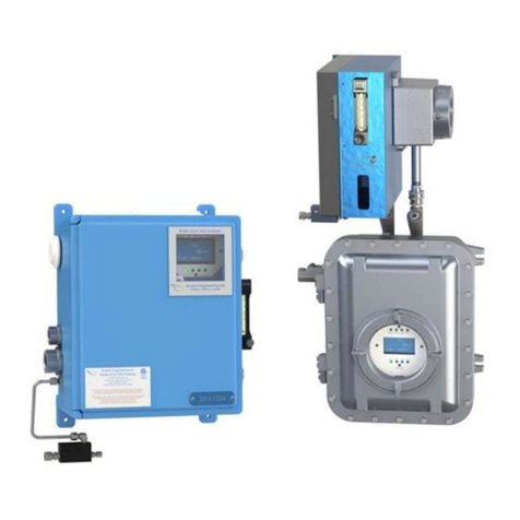
Envent
Envent 331S User manual

Envent
Envent 131S-T4 User manual

Envent
Envent 330S User manual
Popular Measuring Instrument manuals by other brands

SureShot
SureShot PINLOC 6000iPSM user manual
thermastor
thermastor Quest Sentry user guide
Arun Microelectronics LTD
Arun Microelectronics LTD PVU3 User instructions
LineEye
LineEye LE-8600X quick start guide

KEPCO
KEPCO INTELLECT-69 Series Installation & operating instructions
Delta-T Devices
Delta-T Devices WET150 quick start guide
