Envent 330S User manual

Hydrogen Sulfide Analyzer
Model 330S & 331S
Model 330SDS & 331SDS
User’s Manual
Last Updated: December 12, 2022
Revision: 2.8


Table of Contents
1.0 Introduction_______________________________________________________________________ 1
1.1 About This Manual__________________________________________________________________________ 1
1.2 Warranty & Liability Statements _______________________________________________________________ 1
1.2.1 Limitation of Warranty ____________________________________________________________________ 2
1.2.2 Disclaimer ______________________________________________________________________________ 2
1.3 Safety Information__________________________________________________________________________ 2
1.3.1 Key Symbols ____________________________________________________________________________ 3
2.0 Equipment overview ________________________________________________________________ 4
2.1 Theory of Operation ________________________________________________________________________ 4
2.2 Analysis Cycles_____________________________________________________________________________ 6
2.3 Dual Sensor Analysis cycle (SDS) ______________________________________________________________ 7
2.4 Technical Specifications _____________________________________________________________________ 8
3.0 Installation_______________________________________________________________________ 10
3.1 Unpacking _______________________________________________________________________________ 10
3.1.1 Standard spare parts for 330S H2S analyzers: _________________________________________________ 10
3.1.2 Standard spare parts for 331S H2S analyzers: _________________________________________________ 11
3.2 Site Requirements _________________________________________________________________________ 11
3.3 Mounting Requirements ____________________________________________________________________ 12
3.3.1 Space Requirements _______________________________________________________________________ 14
3.3.2 Sample Point Selection___________________________________________________________________ 15
3.3.3 Sample inlet & sample sweep______________________________________________________________ 15
3.3.4 Vent line_______________________________________________________________________________ 15
3.3.5 Sample Volume & Flow Rate_______________________________________________________________ 16
3.3.6 Installation of Analyzer Components ________________________________________________________ 17
4.0 Operation & Configuration___________________________________________________________ 24
4.1 Start-up Procedure ________________________________________________________________________ 24
4.2 Analyzer Display Interface___________________________________________________________________ 25
4.3 Calibration Procedure ______________________________________________________________________ 26
4.3.1 H2S Gas Calibration ______________________________________________________________________ 26
4.3.2 Re-zero Sensor Procedure ________________________________________________________________ 28
5.0 Maintenance______________________________________________________________________ 29
5.1 H2S Sensing Tape Change Procedure __________________________________________________________ 30
5.2 Sample Conditioning System Cleaning Procedure _______________________________________________ 31
5.2.1 Material List____________________________________________________________________________ 31
5.2.2 Cleaning Procedure______________________________________________________________________ 31

6.0 Troubleshooting __________________________________________________________________ 33
Appendix A - Recommended Spare Parts List__________________________________________________ 43
Appendix B –Sealing Compound Information _________________________________________________ 44
Appendix C –Safety Data Sheet for H2S Sensing Tape ___________________________________________ 47
Appendix D –Risk assessment –Safety information_____________________________________________ 52
List of Figures
Figure 1. H2S Analyzer Principle of Operation _____________________________________________________________ 5
Figure 2. H2S Analysis Cycle ___________________________________________________________________________ 6
Figure 3. Space Requirements for the 330S & 331S H2S Analyzers ____________________________________________ 14
Figure 4. 331S Recommended Venting for 331S (Same for 330S model) _______________________________________ 16
Figure 6. Sample Chamber (exploded view) _____________________________________________________________ 19
Figure 7. Envent's Humidifier for 330S & 331S (PN 3100006) ________________________________________________ 21
Figure 8. Humidfier Unit Installed in a 331S H2S Analyzer __________________________________________________ 22
Figure 9. Eductor Block (Venturi Effect) _________________________________________________________________ 23
Figure 10. 330S Display (left) & 331S Display (right) _______________________________________________________ 25
Figure 11. 331S & 331SDS Sensing Tape Change Procedure (Same as 330S & 330SDS models) _____________________ 30
List of Tables
Table 1. 330S/331S H2S Analyzer Specifications ___________________________________________________________ 9
Table 2. Sample Volume & Flow Rate___________________________________________________________________ 16
Table 3. Aperture Strips & Ranges _____________________________________________________________________ 20
Table 4. Display Button Description/Function____________________________________________________________ 26
Table 5. Display LED Description/Function ______________________________________________________________ 26
Table 6. H2S Sensing Troubleshooting _________________________________________________________________ 36
Table 7. Sensing Tape Troubleshooting_________________________________________________________________ 38
Table 8. Electronics Troubleshooting __________________________________________________________________ 41
Table 9. Sample Conditioning System Troubleshooting____________________________________________________ 42
Table 10. Calibration Troubleshooting _________________________________________________________________ 42
Table 11: Recommended Spare Parts __________________________________________________________________ 43
Table 12. Hydrogen Sulfide Properties _________________________________________________________________ 52
Table 13. Hydrogen Sulfide Quantities & Health Effects ____________________________________________________ 53
Table 14: Risk Assessment ___________________________________________________________________________ 56

Envent Engineering Ltd - 330S/DS & 331S/DS User Manual –Revision 2.8
1
1.0 INTRODUCTION
1.1 About This Manual
This manual provides all the necessary information to install, operate and maintain the 330S,
330SDS, 331S and 331SDS model H2S Analyzer units and the related options. This manual is
intended for all technical level users.
The Envent 330S/331S hydrogen sulfide (H2S) Analyzer is a uniquely rugged and simple design that
utilizes lead acetate-based detection which provides a linear and interference-free output of H2S
concentration. This analyzer can measure a wide range of H2S concentrations from parts per billion
(ppb) concentrations to parts per million (ppm) concentrations. With the addition of a dilution
sample system, it can read high concentrations in percentage up to 100%. There are other options
available such as the sample system for H2S analysis in liquids or the addition of a hydrogen
reaction furnace for total sulfur measurements.
This document will be referring to models 330S and 331S. However, the information applies equally
to the 330SDS and 3301SDS (dual sensor), unless otherwise stated. To clarify, the difference
between an S model and an SDS model analyzer is the second sensor. The "SDS" has the capability
to measure H2S from two different samples at the same time.
1.2 Warranty & Liability Statements
Products produced and supplied by the manufacturer (Envent Engineering Ltd), unless otherwise
stated, are warranted against defects in materials and workmanship for up to 18 months from the
shipping date or up to 12 months from the start-up date (whichever comes first). During the
warranty period the manufacturer can choose to either repair or replace products which prove to
be defective.
The manufacturer or its representative can provide warranty service at the buyer's facility only
upon prior agreement. In all cases, the buyer has the option of returning the product for warranty
service to a service facility designated by the manufacturer or its representative. The buyer shall
prepay all shipping charges for products returned to a service facility. The manufacturer or its
representative shall pay all shipping charges for the return of products to the buyer. The buyer may
also be required to pay round-trip travel expenses and labour charges (at prevailing labour rates) if
the warranty has been violated. The warranty may be considered violated for any of the reasons
listed below.

Envent Engineering Ltd - 330S/DS & 331S/DS User Manual –Revision 2.8
2
1.2.1 Limitation of Warranty
The foregoing warranty shall not apply to defects arising from:
•Improper or inadequate maintenance of the product by the user
•Improper unpacking or installation procedures
•Inadequate site preparation
•Unauthorized modification or misuse of the product
•Operation of the product in unfavorable environments such as at high temperatures, high
humidity, or in corrosive atmospheres
•Operation of the product outside of the published specifications
Envent Engineering Ltd carries no responsibility for damage caused during transportation or
unpacking, unless otherwise specified in the incoterms.
An extended warranty may be available with certified start-up. Contact Envent Engineering Ltd for
details.
Envent Engineering Ltd reserves the right to change the product design and specifications at any
time without prior notice.
1.2.2 Disclaimer
No other warranty is expressed or implied. The manufacturer specially disclaims the implied
warranties of merchantability and fitness for a particular purpose. The sole remedy of the buyer
shall in no case exceed the purchase price of the analyzer. The manufacturer shall not be liable for
personal injury or property damage suffered in servicing the product. The product should not be
modified or repaired in any manner differing from procedures established by the manufacturer.
1.3 Safety Information
The procedures and settings outlined in this manual constitute what is considered proper use of
the equipment in question. The equipment was designed and tested under the assumption that
these procedures and settings will be adhered to. Applying values outside of the provided ranges
(such as permitting excessive pressures) or modifying provided procedures is considered improper
use of the equipment. Envent Engineering Ltd is not responsible for any injury or property damage
caused by improper use of the equipment. Once in the field, the user is solely responsible for the
safe operation of the equipment.

Envent Engineering Ltd - 330S/DS & 331S/DS User Manual –Revision 2.8
3
1.3.1 Key Symbols
The following symbols are used throughout the manual to call attention to important information.
We recommend familiarizing yourself with them before reading further.
Indicates a potential hazard that, if not properly addressed, could result in damage to the
equipment or injury to the operator
Caution: hot surface.
Indicates additional information intended to help clarify an earlier statement or to aid in the
reader’s understanding of a given topic.

Envent Engineering Ltd - 330S/DS & 331S/DS User Manual –Revision 2.8
4
2.0 EQUIPMENT OVERVIEW
2.1 Theory of Operation
Envent's models 330S and 331S H2S analyzers use ASTM D4084 –07: Standard Test Method for
analysis of hydrogen sulfide in gaseous fuels (Lead Acetate reaction rate method). This method
uses lead acetate impregnated paper. Throughout this document the term lead acetate tape will
be written as "H2S sensing tape".
The H2S sensing tape reacts when in contact with hydrogen sulfide by the compound relationship
shown below. This tape does not react to any other sulfur compounds in the gas stream. This
makes it free from interference when more than one sulfur compound is present in the sample
stream. The H2S reaction is visibly evident by a brown stain directly on the H2S sensing tape.
COOHCHPbSCOOCHPbSH OH 3232 2)( 2+⎯⎯ →⎯+
Equation 1: H2S & Lead Acetate Reaction
The electronics built into the models 330S and 331S have been programmed to measure the rate
of darkening over time which, in turn, gives the hydrogen sulfide concentration level. When no
H2S is in contact with the H2S sensing tape, the analyzer sensor reads 1000 mV (+/- 100 mV).
The sensor block has a LED and a photodiode detector. The LED emits a red beam of light which is
reflected off the H2S sensing tape to the photodiode which detects the light intensity. The darker
the H2S sensing tape becomes, when in contact to H2S, the less light the photodiode detector
receives reducing the millivolt value, which in turn, increases the H2S value. The "SDS" models
uniquely measures rate of change on both sides of the H2S sensing tape, allowing for
simultaneous readings of two separate samples.

Envent Engineering Ltd - 330S/DS & 331S/DS User Manual –Revision 2.8
5
Figure 1: H2S Analyzer Principle of Operation
Figure 1 above, illustrates flow and pressure regulated, filtered sample gas passing through the
humidifier to the sample chamber. An aperture in the sample chamber, which differs in sizes
depending on the application, allows the gas to come into contact with the H2S sensing tape,
creating a brown stain.
Flow and pressure are the most important variables when measuring H2S and must be kept at a
constant state for the analyzer to measure H2S properly. Pressure should be kept at a constant 15
psig, unless otherwise stated. The lowest pressure found to be tolerable for proper H2S
measurement is 0.5 psig. Flow must be kept at a constant flow of 2 cm (approximately 83.63
cc/min). A change in flow of +/- 1 cm affects the reading by 10% of full range.

Envent Engineering Ltd - 330S/DS & 331S/DS User Manual –Revision 2.8
6
2.2 Analysis Cycles
The analysis of the color rate of change on the H2S sensing tape is measured in analysis cycles. An
analysis Cycle lasts up to a maximum of 720 seconds (12 minutes).
Do not change the Maximum Analysis Time, consult Envent Engineering Ltd.
Analyzers sold prior to Mid-August 2016 are set to have a 360 second analysis cycle.
Once an analysis cycle is complete, the motor moves the H2S sensing tape giving the sensor block
new tape surface area to start the analysis again. In normal operation, if the analyzer is being
exposed to H2S within its range, the analysis cycle should last between 150 to 210 seconds (1.5 to
2.5 min); the cycle lasts 720 seconds if no H2S is present.
Figure 2: H2S Analysis Cycle
Figure 2 shows a complete analysis cycle from when the motor has finished advancing the H2S
sensing tape from a previous analysis (1) to the end of the current analysis (4). Once the H2S
sensing tape has finished moving and new tape surface area is exposed, the reflection of light
from the LED to the photodiode detector is at its maximum and results in a voltage output from
the sensor block of 1000 mV (+/- 100 mV). This mV reading is captured by the analyzer, and it is

Envent Engineering Ltd - 330S/DS & 331S/DS User Manual –Revision 2.8
7
referred to as the "Zero Voltage" or “mV Zero”. The zero voltage will vary for each surface area of
the H2S sensing tape and will represent the starting point for the H2S reading for that cycle.
From stage (2) to (4) the H2S value starts increasing as the millivolt value drops from exposure to
H2S. This stage is called "RRA Analysis". The RRA stands for Rapid Response Algorithm, and it is
the instantaneous H2S readings calculated every 67 mS. As the H2S sensing tape darkens, the RRA
value starts increasing every second. Although the RRA values are calculated almost
instantaneously, they are not as accurate as the final reading obtained at the "Concentration
Calculation" stage (3) to (4). However, RRA values can be used as a trigger alarms setpoint in case
the application requires a rapid response time (less than the RRA Analysis completion). The first
part of the RRA Analysis (2) to (3) completes when the mV value drops 100 mV from the zero
voltage. After the 100-mV drop, stage (3) to (4) "Concentration Calculation" starts.
On this stage, the H2S slope is optimal for calculating the final H2S value for that Cycle. Algorithms
are used by the controller board to calculate as accurately as possible the H2S final value. Once
the final value is obtained, it will stay at that value (shown in the display and 4-20 mA analog
outputs) until the next cycle has finished and updates the H2S current reading. This stage will
always be 1/5 of the amount of time it takes stage (2) to (3) to complete. Thus, if stage (2) to (3)
took 600 seconds, then stage (3) to (4) will take 120 seconds.
It is important that the analyzer is used for its calibrated H2S range. Do not use this unit for an
application that will require readings outside of its calibrated range. This will cause the H2S
sensing tape to run out faster and may cause less accurate readings. The range is determined by
the aperture strip in the sample chamber. For more information analyzer ranges, refer to
"Aperture Strip" on page 20.
2.3 Dual Sensor Analysis cycle (SDS)
Dual sensor analyzers have two sensors that read H2S from two different samples at the same
time (example: Sensor 1: 0-20 ppm & H2S Sensor 2: 0-200 ppm H2S). The analysis cycle process is
the same per sensor as explained earlier in this section; however, some extra algorithms have
been implementing to help with the interaction between the two sensors and their analysis
cycles' timing.
Both analysis cycles for each sensor will always start at the same time. When the motor moves
and new H2S sensing tape area is exposed, a new analysis cycle has started for both sensors.
However, the analysis cycles from each sensor will finish at different times. Either sensor 1 or
sensor 2 will finish its analysis cycle first. Regardless of which sensor finishes first, the analyzer
will wait for the other sensor to complete its analysis cycle. Once both sensors have completed

Envent Engineering Ltd - 330S/DS & 331S/DS User Manual –Revision 2.8
8
their analysis cycles, the motor will move and new H2S sensing tape area is exposed for a new
analysis cycle.
It is important to clarify that when the first sensor has finished its analysis cycle, even when it is
waiting for the second sensor to complete its analysis cycle, it immediately updates any outputs
associated with that sensor (Analog output 4-20 mA, alarms, display H2S value, etc.).
2.4 Technical Specifications
Analyzer Specification
Measurement
Method
ASTM D4084 - 07: Standard Test Method for Analysis of Hydrogen Sulfide
in Gaseous Fuels (Lead Acetate Reaction Rate Method)
Ambient
Temperature
0-50 °C (standard) consult factory for other requirements, 0 to 90%
humidity (non-condensing)
Power
12-24 VDC @ less than 3W
Or, 100-240 VAC 50/60 Hz, 5W,
(300W when total sulfur option is included)
Fuse Rating: 5 Amps, 250V, Slow blow, Size: 0.201'' Dia x 0.787'',
Package/Case: 5 mm x 20 mm
Battery (for 1d Controller Board only): Lithium 3.6V, Dia 0.571'' & 0.992''
Long
Electrical
Certification
330S-DS
Class I, Division 1 Groups B C D T3C Tamb 0 °C to + 50 °C
331S-DS
Class I, Division 2 Groups B C D T3C Tamb 0 °C to + 50 °C
For more information on Hazardous location certification, refer to the
Envent’s Website.
Output Ranges
Standard ranges are between 10-100 ppb and 0-100 ppm
Response Time
20 seconds to 90% of step change
Accuracy
±1.5% of full range on channel 1 (for SDS Models, channel 2 has an
accuracy of ± 2.0%).
For dilution (option): ±2.5%
For Total Sulfur (Option): ±2.0%
For PPB (Option): Based on "base noise average"
Display
Graphic Liquid Crystal Display menu is scrolled by internal button or
magnetic wand (330S)
Outputs
Two 4-20mA outputs (loop power required), optional 4-20mA powered
output boards are available
Serial Communication:
(1) RS-232 Modbus protocol

Envent Engineering Ltd - 330S/DS & 331S/DS User Manual –Revision 2.8
9
Outputs
(continued)
(3) RS-485 Modbus protocol (One RS-485 for remote display option)
Ethernet port as an optional feature
4 SPDT relays (120 VAC 5A maximum)
4 solid state solenoid drivers
Low Tape Sensor
Utilized for an alarm is when the H2S sensing tape needs to be changed
Optional Features
Total Sulfur
(Appendix E)
Utilized when all sulfur compounds need to be measured. A Total sulfur
reaction furnace is added which allows the analyzer to measure total
sulfur
Dilution Sample
System
(Appendix F)
Utilized when the analyzer needs to measure ranges above 100 ppm. A
permeable membrane dilution system
Liquid Sampling
Utilized when a liquid sample conditioning system is required to
measure hydrogen sulfide in Liquids
Parts Per Billion
Utilized when analyzer requires to read in parts per billion (<1 ppm)
Low Pressure
Switch
Utilized for alarming when sample pressure drops below 10 PSI
AO Powered
Boards
Utilized for loop-powered analog outputs
Expander AO
Board
Utilized when more than two analog outputs are required
Ethernet Port
Utilized for TCP/IP communication capabilities
Auto Calibration
Utilized to initiate a calibration based on time of day or manually
Table 1: 330S/331S H2S Analyzer Specifications

Envent Engineering Ltd - 330S/DS & 331S/DS User Manual –Revision 2.8
10
3.0 INSTALLATION
3.1 Unpacking
Upon arrival, the packaging should be immediately inspected for any external damage that may
have occurred during shipping. If any damage is present, please contact Envent Engineering Ltd
and request that the carrier's agent be present when the analyzer is unpacked. If a disagreement
arises, the incoterms agreed to by the seller and the customer will overrule any dispute.
Once the integrity of the packaging has been confirmed, open the shipping container, and remove
the packing materials from the shipping box. Remove all provided components from the shipping
container and inspect them for any damage that may have been sustained during shipping.
Compare the provided components to the shipping manifest to ensure that all parts are present.
The 330S H2S analyzer with a standard Sample conditioning system weight approximately 105 lb.
Unpacking and transporting requires a minimum of two persons.
Make sure the start-up kit is complete (refer to list below). For some special and more complex
analyzers, there might be extra parts in the start-up kit (refer to packing slip).
3.1.1 Standard spare parts for 330S H2S analyzers:
1. 330S Customer Binder
•Customer Manual(s) and Addendums
•Factory Calibration Certificate
•Factory Configuration
•Drawing Package
2. USB flash drive (containing all documentation)
3. 300' H2S Sensing Tape. Part No. 2000040
4. 1 Liter Analyzer Fluid. Part No. 2000035
5. Funnel
6. 330S Serial Comm. External Cable (USB to Mini USB). Part No. 1300245
7. Humidifier (uninstalled). Part No. 3100006 (Part No. 3100007 for SDS)
8. Bolts For explosion proof enclosure (x22)

Envent Engineering Ltd - 330S/DS & 331S/DS User Manual –Revision 2.8
11
3.1.2 Standard spare parts for 331S H2S analyzers:
1. 331S Customer Binder
•Customer Manual(s)
•Factory Calibration Certificate
•Factory Configuration
•Drawing Package
2. USB flash drive (containing all documentation)
3. 300' H2S Sensing Tape. Part No. 2000040
4. 1 Liter Analyzer Fluid. Part No. 2000035
5. Funnel
6. 331S Serial Comm. External Cable (USB to Mini USB). Part No. 1300245
7. Humidifier (uninstalled). Part No. 3100006 (Part No. 3100007 for SDS)
Envent Engineering H2S Sensing Tapes are suitable for use, if stored in the original sealed
package, for 10 years from date of manufacture. Tapes should be stored in a cold dry location. If
the seal on the package has been broken in storage, the H2S Sensing Tape should be discarded.
3.2 Site Requirements
The model 331S & 331SDS are designed for cETLus Class 1, Division 2, Groups BCD, Temp Code
T3C (Tamb 0°C to 50°C). These models are designed for indoor use only. Ensure that the analyzer
received is suitable for the electrical classification of the installation site.
The model 330S & 330SDS are designed for cETLus Class 1, Division 1, Groups BCD, Temp Code
T3C (Tamb 0°C to 50°C). These models are designed for indoor use only. Ensure that the analyzer
received is suitable for the electrical classification of the installation site.
Substitution of components may impair intrinsic safety and suitability for Class I, Division 1.
Substitution of components may impair suitability for Class I, Division 2.
The glass window on the XP enclosure must remain installed in order to maintain area
classification.

Envent Engineering Ltd - 330S/DS & 331S/DS User Manual –Revision 2.8
12
3.3 Mounting Requirements
The analyzer should be mounted in an enclosed area in which it is not exposed to vibrations,
excessive pressures, extreme temperatures, or environmental variations.
The selected installation site should provide adequate room for maintenance and repair
procedures.
The installation site should be as close as possible to the process stream being measured. The
sample delivered to the analyzer must be representative of the stream and as such, should be
taken from a point as close as possible to the analyzer. This proximity will prevent lag times and
sample degradation in the lines.
No modifications or repairs to the flame paths are permitted.
Substitution of components may impair flameproof safety and suitability for Class I, Division 1.
All NPT thread entries must meet the minimum requirement of 5 threads.
XP enclosures must have conduit plugs installed for unused conduit entries.
Conduit seal(s) must be installed at a minimum distance of 18'' from any XP enclosure's conduit
entries.
Conduit seals must be poured after wiring is completed and before powering up the unit.
The XP enclosure covers must be installed and fully engaged to maintain area classification. They
must be secured with the provided 6/32 x ½ set screw. A 1/16 hex key is required for removal.
When operating in low temperatures the flame arrestors and sample inlet line must be properly
insulated to prevent the cooling of the sample gas.
The analyzer’s input voltage range shown in Certification Nameplate (e.g., 120 – 240VAC) is
limited when installing external devices (e.g., Solenoids).
Before opening line pressure, be sure that all port connections, sample sweep and sample
conditioning system are securely installed.
This unit requires a disconnect device rated 24 VDC and 5A max. It must be protected by a circuit
breaker rated 24 VDC and 5A max, and it is to be installed in accordance with local electrical
codes.

Envent Engineering Ltd - 330S/DS & 331S/DS User Manual –Revision 2.8
13
This unit requires a disconnect device rated 240 VDC and 5A max. It must be protected by a circuit
breaker rated 240 VDC and 5A max, and it is to be installed in accordance with local electrical
codes.

Envent Engineering Ltd - 330S/DS & 331S/DS User Manual –Revision 2.8
14
3.3.1 Space Requirements
Figure 3: Space Requirements for the 330S & 331S H2S Analyzers

Envent Engineering Ltd - 330S/DS & 331S/DS User Manual –Revision 2.8
15
Make sure to leave at least 1 foot of extra space on the left side of the 330S H2S analyzer. This will
allow proper opening of the side door located at the upper blue chassis where the H2S sensing
tape is located.
3.3.2 Sample Point Selection
The sample to the 330S/331S H2S analyzer must be representative of the process stream and
should be taken from a point as close as possible to the analyzer to avoid lag times and sample
degradation in the tubing. A probe must be installed vertically on a horizontal section of pipe
ensuring that the sample is drawn from the middle third of the pipeline.
An optional Genie GPR Probe regulator may be used. The function of this probe is to ensure a
clean dry sample to the analyzer and to reduce the pressure of the sample. The lower pressure
will improve the response time of the analyzer. Refer to Figure 4.
It is advisable that the probe is not installed on a vertical pipe.
3.3.3 Sample inlet & sample sweep
1/4-inch 316 stainless steel tubing and fittings are recommended for the sample inlet and sample
sweep tubing. Sample sweep can be connected to a flare line if available. Refer to Figure 4.
1/8-inch 316 stainless steel tubing can also be used if the response time of the analyzer is of
particular concern.
3.3.4 Vent line
3/8-inch stainless steel tubing and fittings are recommended for the vent line to a maximum of 6
feet in length. ½-inch stainless steel tubing should be used for vent lines exceeding 6 feet. The
tubing should be installed with a slight downward slope and should be as short as possible. Refer
to Figure 4.
The sample vent line must be tubed to atmospheric pressure outside and cannot be connected to
a flare line or header.

Envent Engineering Ltd - 330S/DS & 331S/DS User Manual –Revision 2.8
16
3.3.5 Sample Volume & Flow Rate
The sample should be supplied to the 330S/331S H2S analyzer at 10-15 psig and at a flow of 83.63
cc/min (set flowmeter at 2.0). A bypass sweep is recommended to reduce sample lag time in the
sample line if it is at high pressure or if it is longer than 15 feet (The Standard H2S conditioning
sample system has a bypass sweep). The standard sample tubing material is 1/4" 316 stainless
steel; however, 1/8" stainless steel tubing can be used if the response time is critical (refer to
Table 2: Sample Volume & Flow Rate
Tube
Size
(")
Tube
Gauge
ID (")
ID (cm)
Flow
(SCFH)
Flow
Std.
(cc/min)
Pressure
(PSIA)
Lag
Time per
100'
(min)
Lag
Time per 100'
(sec)
3/8
20
0.319
0.810
5
2359
800
36.30
2178
3/8
20
0.319
0.810
5
2359
200
9.07
544
3/8
20
0.319
0.810
5
2359
50
2.27
136
1/4
20
0.181
0.459
5
2359
800
11.69
701
1/4
20
0.181
0.459
5
2359
200
2.92
175
1/4
20
0.181
0.459
5
2359
50
0.73
44
1/8
20
0.081
0.205
5
2359
800
2.34
140
1/8
20
0.081
0.205
5
2359
200
0.59
35
1/8
20
0.081
0.205
5
2359
50
0.15
9
Carbon steel sample line and/or fittings are not acceptable.
Table 2: Sample Volume & Flow Rate
Figure 4: 331S Recommended Venting for 331S (Same for 330S model)
Other manuals for 330S
2
This manual suits for next models
3
Table of contents
Other Envent Measuring Instrument manuals

Envent
Envent 330S-Ex User manual
Envent
Envent 132S User manual

Envent
Envent TFS1 User manual
Envent
Envent 331S User manual
Envent
Envent 131S User manual
Envent
Envent 330 Configuration guide
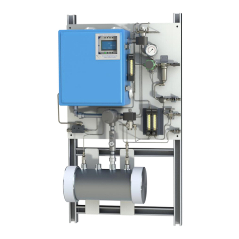
Envent
Envent 330S User manual

Envent
Envent 131S-T4 User manual

Envent
Envent 131S Mounting instructions

Envent
Envent 330S User manual
Popular Measuring Instrument manuals by other brands
Thermokon
Thermokon FT-RDF18+ quick start guide

horiba
horiba LAQUAact D-75 Quick manual
Keysight Technologies
Keysight Technologies 34959A Service guide
Thermo Scientific
Thermo Scientific iCAP 7000 Series Hardware installation

Ametek
Ametek JOFRA DTI050 A Reference manual
RADWAG
RADWAG MA X2 Synergy user manual
