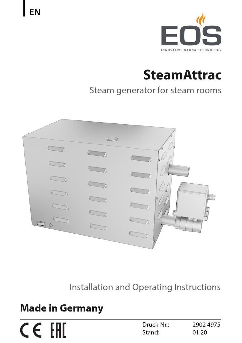
EOS SteamTec Premium Troubleshooting guide

1
D
IP x4
Made in Germany
SteamTec Premium
steam generator
print no. 29343751en 35.12
HD 7
GB Installation instruction and
operation manual

2GB
English
Inhalt
1. General information .............................................................................................6
1.1 Device functions ............................................................................................6
1.2 Installation locations and connections...........................................................7
1.3 Installation overview ......................................................................................8
2 Device installation .................................................................................................9
2.1. Skeleton construction installation .................................................................9
2.1.1 Fresh water and wastewater..................................................................9
2.1.2 Connections for water feed and drainage .............................................9
2.2. Dismantling the steam generator hood .......................................................9
2.3. Temperature sensors..................................................................................10
2.4. Control panel ..............................................................................................10
2.5. Steam jet ....................................................................................................10
2.6. Steam line ..................................................................................................11
2.7. Steam connections ....................................................................................11
2.8. Installation of the fragrance system............................................................12
2.9. Ventilation...................................................................................................13
2.9.1. Supply fan ..........................................................................................13
2.10. Illumination ...............................................................................................14
2.10.1 Installation dimensions for RGB or halogen spotlights ......................14
2.10.2 Connection of the RGB coloured light................................................15
3. Electrical installation ..........................................................................................16
3.1. Connection lines.........................................................................................16
Assembly of the steam generator housing ........................................................17
3.2. Overview of the components on the printed circuit board ..........................18
3.3. Terminal diagram ........................................................................................19
4. Functional descriptions ....................................................................................20
4.1. Setting the nominal temperature / time, T2/T4 key....................................21
4.2. Fragrance .................................................................................................21
4.3. Exhaust air fan .........................................................................................21
4.4. Supply air fan ............................................................................................21
4.5. Colour change light (RGB LED) ...............................................................21
5. Customer programming (User level) ,see page 50 .........................................22
5.1 Programming ..........................................................................................22
Steam Tec Premium programming table ......................................................22
6. Software update.................................................................................................23
6.1. Preparation of the hardware.......................................................................23
6.2. Implementation of software update ............................................................23

3
GB
7. Remote control...................................................................................................24
USER LEVEL.........................................................................................................25
8. User level ...........................................................................................................26
8.1 Operation with display .................................................................................26
8.2 Setting the time.......................................................................................26
8.3 Temperature control ................................................................................26
8.4 Fragrance ...................................................................................................26
8.5 Exhaust air ..................................................................................................26
8.6 Reserve relay 14 .........................................................................................27
8.7 Reserve relay 15 .........................................................................................27
9. Service level.......................................................................................................27
9.1 Supply air ....................................................................................................27
9.2 Stand-by ......................................................................................................27
9.3 Tank flushing with descaler..........................................................................27
9.4 Room illumination light ................................................................................27
9.5 Operating hours counter..............................................................................27
9.6 Flushing process counter ............................................................................27
10. Steam control.................................................................................................28
11. Flushing and descaling ..................................................................................29
12. Replacing the heater register...........................................................................30
13. Error messages..............................................................................................30
14. Service .............................................................................................................31
15. Maintenance ....................................................................................................31
16. Technical data ..................................................................................................32
Spare parts for Steam Tec steam generator ..........................................................33
Service Address: ....................................................................................................34
Guarantee ..............................................................................................................34
Handling procedures for return shipments (RMA) - Details for all returns ! ...........35

4GB
• Priortoinstallation,pleasereadtheseinstructionsthroughcarefullyandstorethem.
They provide valuable information on the proper installation of your steam genera-
tor.
• Thesteamgeneratormustbeinspectedimmediatelyafterunpackingforcomplete-
ness and for possible transport damages. The EOS plants shall not bear any liability
for damages which have been caused through transport or intermediate storage.
The following are included in the scope of
delivery:
• (1)Steamgenerator
• Skeletonconstructionset:
- (2) Drilling template
- (3) Wall plug for sensor installation
- (4) Wall plug for steam discharge
- (5) Flush-mounted housing for panel
- (6) Assembly instructions
• (7)Steamjet
• (8)Fragrancejet4mm/G1/2"
• (9)4Screws45x40
• (10)4DowelM8
• (11)Operatingpanelwith7mconnection
line
• (12)Sensor
• (13)Sensorpackageleaet
• (14) 0.5 m metal-braided pressure hose
3/8 - 500 - 3/4
• (15)0.4mexiblehose28-22withhose
clamp
• (16)7mextensionforsensor
• (17)5lstoragetankfordescalerwithlevel
detection
• (18)Operatinginstructions
(4&7)
(9&10) (11)
(5)
(3)
(8)
(16)
(14)
(15)
(1), (2), (6), (17) and (18) are not shown here
(8)
(12)
(13)
(16)

5
GB
Connection for fresh water
Caution!
A water treatment system must
be fitted upstream depending on
the hardness of the water
Pump
descaler
Pump
fragrance
Steam line connection
4-9 kW
1" inside thread with
screw connection
12-18 kW
Ø 35 mm inside thread
withscrewconnectionfor
soldering.
Overpressure-
drain hose
Outlet connections for descaling
and for emptying the water tanks
Feedthroughs for
electric lines
Terminal strip
Steam line
Fresh water
line
Safety over-
pressure
valve
Safety temperature
limiter
Control electron-
ics
Steam generator
Solenoid
valve, flushing
Outlet connections for
descaling
Overpressure-
drain hose
Lines for fragrance and
descaler

6GB
1. General information 1.1 Device functions
Your steam generator is a high-quality,
electrically-operated unit. Operation takes
place via a panel with switching possibilities
for steam, fragrance, exhaust air and light,
which can be installed both inside the cabin
as well as on the unit. The temperature con-
trol also takes place via the panel.
The electrical / electronic components and
the steam tank made of stainless steel are
arranged in a housing.
The water feed is automatically controlled,
whereby a manual drain, for example for
cleaning the device, is possible.
The housing consists of deep-drawn plastic.
The steam tank and all wear parts are made
of stainless steel.
The steam generator works without pres-
sure.
The electrically operated resistance heaters,
which are made of stainless steel, are inte-
grated into the steam tank.
This principle works almost independently of
the water quality.
Permanent steam production is ensured
through the automatic water level control.
The optional supply air fan ensures opti-
mum steam distribution through the supply
of fresh air.
Important note
Contact your water supply company and
ask about the hardness level of your wa-
ter. Within the hardness range I (0-8.4°
German degree of hardness), the device
generally works without faults and is des-
caled through the descaling unit installed.
Should your water lie within the hardness
ranges II - III, a water treatment system
(waterlter)mustbeinstalledinfrontofthe
evaporator.
Conversion for water hardness units
°dH °e °f ppm mMol/l
German degrees 1°dH = 1 1 2 18 0
English degrees 1°e = 0 1 1 14 0
French degrees 1°f = 0 0 1 10 0
CaCO3(USA) 1 ppm = 0 0 0 1 0
mMol/l 1 mMol/l = 6 7 10 100 1
Table acc.: (Lit.: Krause, page 35)

7
GB
1.2 Installation locations and con-
nections
• Theassemblylocationofthesteamgen-
eratormayliemax.oneooraboveorbe-
low the steam cabin and the length of the
line between the steam generator and the
steam jet should not exceed 6 m.
If the distance is larger, the steam line
must be selected one dimension larger
than stated in these instructions.
Two steam jets should be provided for
steam generators >9 kW.
Please follow the instructions below for
assembly of the system components.
• The electrical installation must be de-
signed acc. DIN VDE 0100.
The system must be supplied via a separate
power circuit with a residual current circuit
breaker (I Δ= 30 mA) which disconnects
the device at all poles from the mains with
a contact opening width of at least 3mm.
The electrical installation may only be un-
dertaken by a licensed electrician.
• The steam generator water connec-
tion is a 50 cm-long reinforced hose (R
3/8") on a connection bracket provided
on-site (R 1/2") with 1-6 bar water pres-
sure, directly from the water mains.
At more than 6 bar water pressure, a pres-
sure reducing valve (setting 4-6 bar) is to
be provided.
• Forthewaterdrainforcontrolandclean-
ing purposes, the drain must be con-
nected with the outlet via a funnel si-
phon made of heat-resistant material.
The funnel and the drain must be di-
mensioned large enough so that they
arebrieyabletohold5-7lofuid.
Place the collecting funnel at least 30 cm
below the drainage outlet.
• Provide the following connection lines /
empty pipes
Designation Empty pipe Line
Temperature sensor Yes 2 x 0.5 mm²
Wall lamp Yes 2 x 1.5 mm²
Fragrance dosage pump
Yes 4 x 0.75 mm²
Supply air fan Yes 3 x 1.5 mm²
• For the steam line, the minimum
pipe diameter must be 35 mm.
The steam line(s) from the steam gen-
erator to the steam jets should be
made of copper or stainless steel pipe
withsufcientheatinsulation(20mm).
You can nd the position of the
steam jet in the cabin drawing.
The steam line must not be lockable
and it must not be possible to shut it
off. It must be protected against outside
inuences(kinkingordeformation).
Only45°bendsmaybeusedduetoow
reasons.
• Connecttheoptionalsupplyairfanwiththe
steam jet using a pipeline (HT pipe DN 40).
For assembly, please observe the Assem-
bly instructions enclosed with the fan.
Always mount the applica-
ble check valve horizontally.
If possible, do not mount the supply air fan
on the outer wall of the cabin.


8GB
CU 35 mm
1000
300
A
1400
150-250
DN 100
DN 50
CU 35 mm
G 3/8
max
6 bar
A
Scope of delivery
Special accessories
S p e e d
control
Exhaust
air fan
Supply air fan
Fragrance jet
4 mm / G 1/2
Floor drain, Tech-
nology room
Storage container for
fragrance essences
Poppet valve
Mount opposite the steam
jet
Bench
Steam jet
Door
Wall lamp
20 W / 12 V
Fresh air
Control panel
Temperature
sensors
Floor drain,
cabin
1.3 Installation overview
Storage container
for descaler

9
GB
2 Device installation
2.1. Skeleton construction installa-
tion
For the skeleton construction, the skeleton
construction kit included in delivery is re-
quired. Carry out installation of the skeleton
construction according to the Installation
overview.
2.1.1 Fresh water and wastewater
The positions of fresh water and wastewater
are to be provided according to the drilling
template included in the skeleton construc-
tion set.
4,5-9 kW 340 mm
290
510
4,5 - 9 kW 620 mm
1000
300
420
12 - 18 kW 410 mm
12 - 18 kW 670 mm
150
150
2.1.2 Connections for water feed and
drainage
Important notes:
The regulations of EN 1717 or DIN 1988
part 4 must be observed. Suitable measures
must be taken to avoid water owing back
into the drinking water mains. Pipe dividers
or system dividers are suitable for this. Ask
your drinking water supplier or a specialist
sanitary dealer.
2.2. Dismantling the steam generator
hood
• Unscrewandremovethetwoscrews3.2
x 16mm from the hood under the steam
generator.
• Maketheassemblydrillholesaccordingto
the drill template on the wall.
• Inserttheupperfasteningscrewsintothe
dowel and screw in to a wall distance of 5
mm.
• Hookinthesteamgeneratorandscrewin
the lower screws.
30 mm
Electrical installation
area

10 GB
2.5. Steam jet
When positioning the steam outlet
jet, you must ensure that the user cannot
scald themselves later on the hot steam.
The steam outlet temperature at the jet is
approx. 100° C!
At the end of the steam line, in the cabin,
thetransitionsleeve35mmto5/4"inside
thread (skeleton construction set) must be
installedushwiththetiles.
300 300
150 - 250
400
2.3. Temperature sensors
The temperature sensor may not be ar-
ranged directly over the steam nozzle. The
recommended positioning can be found in
the Assembly diagram. There is a sensor
protectiontube½"x120mmforassembly
located in the skeleton construction set.
Thismustbeinsertedintothewall, ush
with the tiles.
Tile
Adhesive
Vapour barrier
ISO panel
Masonry
Tap extension
G 1/2 x 60
O-ring
Reducer
brass
2.4. Control panel
For ush-mounted installation, the ush-
mounted housing (skeleton construction
set) must be inserted into the wall. An emp-
ty tube connection (Ø 20 mm) must be pro-
vided to the steam generator. When tiling,
pleaseensurethatthetwoxingholesin
theush-mountedhousingareleftclear.
Alternatively, it can be mounted in the
housing.
PU panel ISO
min 40 mm Adhesive
Tile
Vapour
barrier
Wall
During assembly, check the run of the ca-
ble and the screw connections

11
GB
2.7. Steam connections
• Screwtheexiblehosewithbraidedstainlesssteelprovidedonthesteamgeneratoronto
thefreshwaterconnection(3/8")tobemadeon-site.
• Thewatertankisemptiedviatheushingprogram,whichrunsautomatically.
• ConnectthesteamlinetothedevicewiththeRGscrewconnection1"x35.
• Steamoutputontherightsideunderthesteamgenerator.
• Screwinthesteamjetwithsiliconesealincludedindeliveryintotheon-site,pre-installed
transitionsleeve5/4"x35.Sealthesteamjetthreadslightly.
• Hangtheoverpressureoutlethoseintothesiphon.
Supply air line
Steam line
2.6. Steam line
The steam line must always be designed
in copper or stainless steel (min. Ø 22 mm,
we recommend 35 mm to prevent noises
developing) for all steam generators, here
narrow 90° bends in 2 x 45° are to be laid.
The steam line insulation should be de-
signedwithIsover,ArmaexHTormateri-
als of the same quality to a thickness of 25
to 30 mm.
When laying the steam line, please ensure
a gradient ( min. 1cm / m ) in the direction
of the steam jet in order to avoid conden-
sation build-up (water trap). The steam
line should not exceed a length of 5 m.
Pressure build-up in the steam line is not
permissible.
As additional equipment for the automatic
fragrance dosage, a ½" sleeve must be
positioned just before the steam jet in the
steam line gradient. It must be ensured
that the fragrances cannot ow via the
steam line into the steam generator.
Supply air line
Steam line
Should several steam jets be mounted in
the cabin as shown in the adjacent diagram
, the connections of the supply air and steam
lines should be placed as close as possible
to the respective steam jet.

12 GB
2.8. Installation of the fragrance system
The optional fragrance dosage valve must be installed in the falling steam line. It must be
mounted as close as possible to the steam generator as shown in the following Figs.
The maximum hose length on the metering pump pressure side is 2 m.
Hose (Ø 2.5 x 1 mm
Clamp
Fragrance dosage valve
CUT-piece35mmx1/2"
(construction side)
When arranging the steam generator under the steam cabin, position the fragrance valve
according to our Fig.
Fragrance dosage valve
to the steam jet
from the steam generator

13
GB
2.9. Ventilation
Thesteamcabinset-uproommustbesufcientlywell-ventilated.Ventilationcanbecar-
ried out via a poppet valve which is included in the additional accessories for the exhaust
air fan. The poppet valve must be connected on-site to an exhaust air pipe which should
lead directly out into the open air. We do not recommend the connection of central ventila-
tion systems due to the risk of possible condensation formation.
For installation of an exhaust air fan (additional equipment) into the exhaust air line, an
empty pipe connection must be provided to the steam generator according to the Installa-
tion overview.
2.9.1. Supply fan
(Additional equipment - recommended from
SteamTec Premium 6.0 kW)
The connection of the supply air (Ø 35 mm in
Cu) with the steam line should be carried out
on-site as close as possible to the steam jet.
Should several steam jets be mounted in
the cabin as shown in the adjacent diagram
, the connections of the supply air and steam
lines should be placed as close as possible
to the respective steam jet.
Supply air line
Steam line
Supply air line
Steam line

14 GB
2.10. Illumination
(Additional equipment)
A connection possibility 230 V / 2A for the on-site transformer max. 12 V / 400 W is avail-
able in the steam generator as a standard measure.
It is still possible to control, for example, an RGB coloured light via the steam generator.
Pleasenddetailsontheconnectionofthedifferentilluminationpossibilitiesinthetermi-
nal diagram further down
2.10.1 Installation dimensions for RGB or halogen spotlights
Ø70 mm
Ø85 mm
ET = 100 mm
13 PE
N
12 V
max. 400 W
230 V / 2A
H1
X3

15
GB
2.10.2 Connection of the RGB col-
oured light
31 32 33 34 35 36 37 38 39
31 32 33 34 35 36 37 38 39
RGB 1
Rgb 2
H2 H4H3
H2 H3 H4
H7H6
H5
RGB
X3
X3
brown
brown
brown
brown
brown
brown
brown
brown
brown red
red
red
Green
Green
Green
blueblue
blue

16 GB
3. Electrical installation
During the electrical installation, the re-
spective VDE, country and EVU regu-
lations must be maintained in their re-
spective valid version. Installation and
inspection work is to be carried out exclu-
sively by a licensed electrician, taking the
valid standards into account.
The power supply must be provided tak-
ing the required line cross-section into ac-
count. The electrical installation must be
designed acc. DIN VDE 0100. The system
must be supplied via a separate electrical
circuit feed line. Furthermore, the steam
generator must be protected by a sepa-
rate residual current circuit breaker (I∆
= 30 mA), which disconnects the device
on all poles from the mains with a contact
opening width of at least 3 mm. The elec-
trical installation may only be undertaken
by a licensed electrician.
All electrical lines connected to the steam generator are to be laid according to the drilling
template on the steam generator in the area of the connection. An approx. 0.5 m cable length
is required for connection to the device. The maximum line length to the operating panel is
7 m!
3.1. Connection lines
Steam Tec
Temperature
Sensor
Steam Tec
Controls
Steam Tec wall
light
20 W / 12 V
Steam Tec
RGB lamp
Steam Tec
Extractor
Steam Tec
blower
2 x 0,75
max. 7 m
included
4 x 1,0
max. 7 m
included
3 x 1,5
230 V or
transformer
(not included)
4 x 2 x 0,8
IY(ST)Y 3 x 1,0 3 x 1,0
All cross-sections are
minimum in mm² CU
optional
150
150
Area for
Electrical installation

17
GB
• Feedallelectricallinesfrombelowthrough
the PG glands or through the rear wall.
• Connect the temperature sensor and in-
stall it according to the drawing.
• Install the operating panel into the pre-
installedush-mountedhousing.
• Laythelinestothegenerator.
• Inserttheoperatingpanelandxwiththe
stainless steel screws 4 x 30 included in
delivery.
• If the operating panel is installed in the
generator hood, the line must be short-
ened to 1.5 m. In the hood, the two screws
are removed, the line is fed through the
rubber guide and the panel is xed with
the two screws.
Now connect the steam generator including
the additional equipment according to the
following terminal diagram.
Chrome
cover
Sensor O-ring O-ring
Reducer
brass
Assembly of the steam generator housing
Fix the steam generator hood with the two screws underneath the housing.

18 GB
1
1
1
2
2
2
F 11
F 10
1
1
1
2
2
2
1
2
K7 F2
1
2
K8 F4
1
2
K11 F5
1
2
K12 F6
1
2
K13 F7
1
2
K14 F8
1
2
K15 F9
F3
1
2
K9
1
2
K10
F 12
SD CARD
X7
+5V
SCL
SDA
GND
X2
1
2
1
X8
2
4 3 21
X1
Lf1 Lf1 Lf1
Lf1 Lf1 L
T620mA T2A 2
1
F13 F1
N
Ne1
Ne2
Ne3
Ne4
K1
K2
K3
K4
K5
K6
X 5
Jumper 3
heater 1
heater 2
heater 3
heater 4
heater 5
heater 6
air-intake fan
exhaust air fan
ball-valve closed
ball-valve open
valve cleanig
valve niveau
light
reserve relais 1
reserve relais 2
NTC-cabine
NTC-heater
Jumper 1
Jumper 2
+12V I aroma-pump
+12V I descaler pump
ground long electrode
ground short electrode
ground descaler-electrode
3.2. Overview of the components on
the printed circuit board
Jumper 3 open operation with display
Jumper 3 closed operation without display
4.5 - 9 kW12 - 18 kW

19
GB
PE
N
L1 L2 L3 8713 14 15 L16
PE
N
PE
NPE
NPE
NPE
NPE
N21 22 23 24 25 26 31 32 33 34 35 36 37 38 39
400 V 3N
AC 50/60 Hz
12 V
max. 400 W
230 V / 2A
230 V
2 A
230 V
2 A
31 32 33 34 35 36 37 38 39
RGB 1
Rgb 2
H1 H2 H4H3
H2 H3 H4
H7H6
H5
RGB
28
27
Temperature sensor, cabin
Control panel
Janitor switch (optional)
Reserve 2
Reserve 1
Cabinet lighting
Exhaust air fan
Supply air fan
Mains
3.3. Terminal diagram
e.g. (to be provided on-
site)
-"Starrysky"
- Audio feed
- Additional heating
Descaler stocks sensor
red
black
orange
brown
red red
red
brown
brown
brown
brown
brown
brown
brown
brown
brown
blue
blue
blue
Green
Green
Green

20 GB
4. Functional descriptions
In normal operation, the time and the temperature are shown in the display alternately at
intervals of 5 seconds.
13:45
SteamTec
Premium
Steam ON/OFF
(T1)
Illumination ON/OFF
(T3)
Fragrance ON/OFF
(T7)
Increase values
(T5)
Set the steam temperature
(T2)
Set the time
(T4)
RGB coloured light
(T8)
Reduce values
(T6)
Onthefollowingpagesyouwillndexplanationsontheoperationandcareofyoursteam
generator. We wish you lots of fun with your SteamTec Premium steam generator and wish
to thank you for placing your trust in us!
The steam generator is switched on/off with the (T1) key.
Other manuals for SteamTec Premium
1
Table of contents
Other EOS Iron manuals

EOS
EOS SteamRock II Premium User manual

EOS
EOS SteamTec Classic Planning guide

EOS
EOS SteamRock II Premium User manual

EOS
EOS SteamAttrac User manual

EOS
EOS SteamRock II Basic User manual

EOS
EOS SteamTec II Basic User manual

EOS
EOS SteamRock II Premium User manual

EOS
EOS SteamRock Premium User manual

EOS
EOS SteamRock Basic User manual