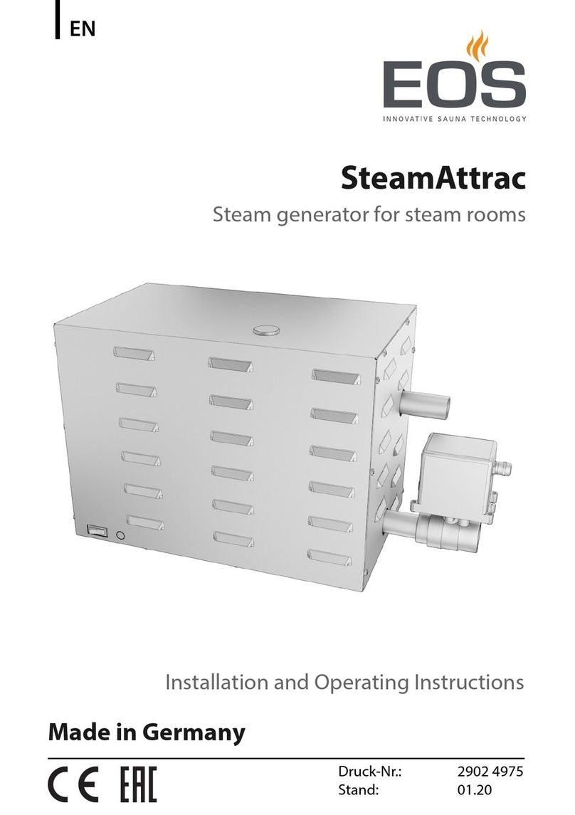
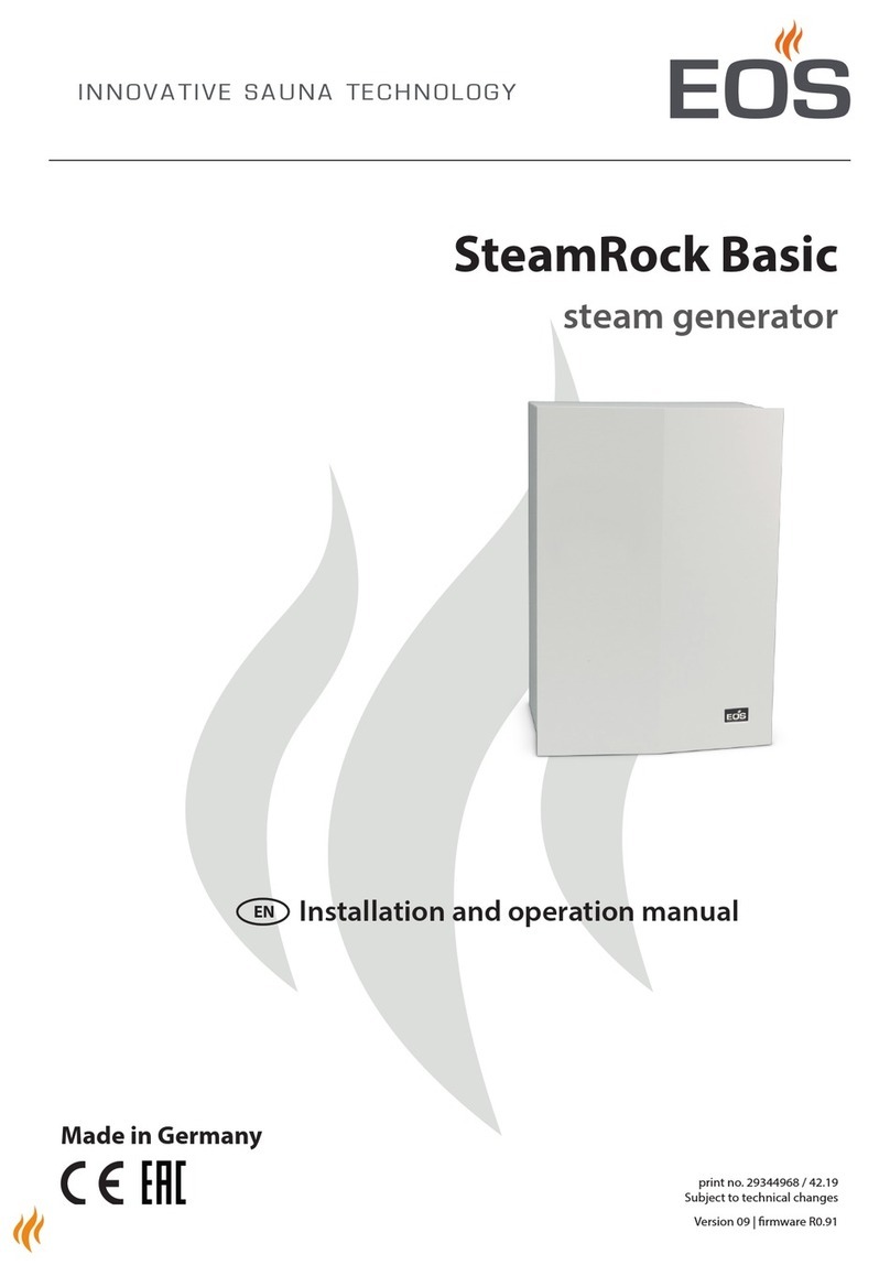
EOS SteamTec II Basic User manual

1
D
Made in Germany
SteamTec II Basic
steam generator
print #29344696 / 36.16
GB Installation and operation manual

2
D
English
Contents
1. Identification and legal notes 4
1.1 Manufacturer 4
1.2 Copyright 4
1.3 Identification of the device 4
1.4 Intended use 4
1.5 Foreseeable incorrect use 5
1.6 Applicable norms 5
2. Safety advice 6
3. Specifications 9
4. Delivery scope 10
5. Installation 11
5.1 Installation overview 11
5.2 Contruction and location of components 12-13
5.3 Prerequisites on the installation site 14
5.4 Mechanical installation 14
5.5 Water supply and drain 16
5.6 Steam pipe connection 16
6. Electrical connection 17
6.1 Steamtec II Basic 18 kW terminals 17
6.2 Steamtec II Basic 9 kW terminals 18
6.3 Inner wiring diagrams 19-20
6.4 Connection to Emotouch II+ Steam 21
6.4 Connection to Emotouch II+ Sauna, Emotec H, Econ H 22
7. Cleaning system 24
7.1 General information 24
7.2 Setup and operation of the cleaning system 25
8. Power selection 26
9. Operation modes 27
10. General operation 29
11. Maintenance and servicing 30
12. Troubleshooting 31
13. Disposal 32
14. Warranty 33

3
EN
Introduction
Dear customer
Thank you very much for purchasing EOS sauna & steam equipment. You have purchased a mod-
ern, technically advanced product which will provide you with years of reliable operation.
EOS steam generators have been designed and tested to comply or exceed the currently applica-
ble European safety norms and are produced in our factory in accordance with the quality man-
agement norms DIN EN ISO 9001:2008.
This installation manual or operating guide is intended for your information. Please read it careful-
ly before installing and operating the steam generator, in order to prevent damages of the device
or physical injuries. Please keep this document for further references.
We wish you a pleasant and relaxing time in your steam room.
Your EOS team.

4
EN
1. Identication
1.1 Manufacturer
EOS Saunatechnik GmbH
Schneiderstriesch 1
D-35759 Driedorf, Germany
Tel.: +49 2775 82-0
Fax: +49 2775 82-431
1.2 Copyright
The copyright owner of the present installation manual and operating guide is EOS Saunatechnik
GmbH.
1.3 Identication of the product
Steam generator SteamTec II, Version„Basic“
1.4 Intended use
The Steamtec II Basic steam generator is intended for production of steam in steam rooms or sau-
na rooms with humid operation. The Steamtec II Basic requires an external control unit which is
not included in the scope of delivery. Third party control units may not be used without prior
written consent of EOS Saunatechnik GmbH.

5
EN
1.5 Foreseeable incorrect use
Following may be regarded as foreseeable incorrect use:
• Steam room size does not match the steam generator power (incorrect power selection).
• Operation without legally required safety and protection features.
• Operation without proper knowledge of the safety advices (chapter 3).
• Operation without adherence to the required operation rules, maintenance and servicing re-
quirements.
• Operation of the device after unauthorized technical alterations or repairs.
• Operation or use by infants or persons with limited mental abilities without the proper prior
instruction.
• Operation or use by persons with certain ailments or health conditions, such as for instance
heart and cardiovascular disorders, which might lead to physical injuries through the use of a
sauna or a steam room (a doctor should be consulted in advance).
1.6 Applicable norms
DIN EN 60335-1:2012-10 Household and similar electrical appliances - Part 1: General re-
quirements
DIN EN 60335-2-53:2012-06 Household and similar electrical appliances. Safety - Part 2-53:
Particular requirements for sauna heating appliances and infra-
red cabins
DIN EN 60335-2-98:2009-04 Household and similar electrical appliances. Safety - Part 2-98:
Particular requirements for air humidiers
DIN EN 60335-2-101:2009-02 Household and similar electrical appliances. Safety - Part 2-101:
Particular requirements for vaporizers
DIN EN 1717:2011-08 Protection against pollution of potable water installations and
general requirements of devices to prevent pollution by back-
ow
DIN 1988-100:2011-08 Codes of practice for drinking water installations - Part 100: Pro-
tection of drinking water, drinking water quality control
DIN EN 55014-1:2012-05 Electromagnetic compatibility - Requirements for household ap-
pliances, electric tools and similar apparatus - Part 1: Emission
DIN EN 55014-2:2009-06 Electromagnetic compatibility - Requirements for household ap-
pliances , electric tools and similar apparatus - Part 2: Immunity
DIN VDE 0100-703:2006-02 Low voltage installations – Requirements for special installations
or locations - Rooms and cabins containing sauna heaters
DIN EN 82079:2012 Requirements for instruction manuals in the European Market

6
EN
2. Safety advices
!DANGER
Risk of re and danger of electric shock.
Risk of re by incorrect installation.
• Make sure to have the steam generator installed only by an ap-
propriately qualied specialist according to the present instruc-
tion manual.
• All electrical connections in the steam generator and other
equipment with a permanent connection may be only carried out
by an appropriately qualied and licensed electrician. All applica-
ble local legal codes and safety requirements should be observed.
In the case of a warranty claim a proof of such installation (e.g.
invoice of the electrician) should be presented.
!DANGER
Risk of health damage by too long operation time.
• If the device is used in a commercial (public) sauna so that it does
not switch o automatically after a certain time, then it should
be appropriately supervised.
• By operation with certain time intervals or by switching through
a remote system the sauna cabin should be visually inspected
before it is switched on.
• This is also required if the device has been set to a stand-by mode
in order to be switched on at a later time.

7
EN
!DANGER
Risk of scalding.
Hot steam may cause burns, scalding and dangerous to life injuries, if
the steam generator has not been properly installed or is operated not
as per its intended use.
• During planning and installation make sure, that the steam
output always remains open and may not be blocked.
• The overpressure release vent and its drain pipe should be in-
stalled and connected so, that it the case of a unforeseen release
of hot water by overpressure there is no risk of scalding.
!DANGER
Danger to life and risk or dangerous to life injuries
The use of sauna by persons with certain health conditions may cause
severe dangerous to life injuries or even death.
• Please consult a doctor before using a sauna if there is possibility
that the use of sauna may lead to heath damages.
• Please make sure to read carefully the present installation manu-
al and operating guide before using the steam generator.

8
EN
!WARNING
Risk of burns through hot surfaces in the device.
The steam generator has hot surfaces, e.g. pipelines, water tank,
which may cause burns.
• Keep a secure distance to hot surfaces of the device.

9
EN
3. Specications
Dimensions H x W x D [mm] 670 x 460 x 350 mm
Installation Wall-mounting, connections on bottom panel
Gewicht [kg] 28 kg (type 1) / 30 kg (type 2)
Water supply pressure [bar] 3 - 8 bar
Operation pressure max. [bar] Pressureless type steam generator
Performance at 3 bar [steam/h] 3 kW - 4 kg/h, 6 kW - 8 kg/h, 9 kW - 12 kg/h, 12
kW - 16 kg/h, 15 kW - 20 kg/h, 18 kW - 24 kg/h
Protection class IPx4
Water tank High grade stainless steel
Internal overheating protection Thermofuse with capillary sensor, 3-pole circuit
breaker
Heating system External heating elements, switchable in 3 kW
steps
Cleaning and drain system Integrated automatic descaling and draining
system, built-in peristaltic pump, external 5 l
container for cleaning liquid with level probe
Water level control Automatic with overheating protection
Control system Steamtec II Basic - not included
Steamtec II Classic/Premium - see control unit
Essence dosing Steamtec II Basic - not included
Steamtec II Classic Premium - integrated peri-
staltic pump, adjustable dosing intensity
Water supply ¾“ external thread
Steam output 1 1/4“ external thread, 2-part brass union includ-
ed in delivery scope
Power supply 400 V 3N AC, 50/60Hz
Power output [kW] type 1 - 3.0 / 6.0 / 9.0 kW (9 kW default)
type 2 - 12 / 15 / 18 kW ( 18 kW default)
Fuse protection [A] type 1 - 3 x 16 A
type 2 - 3 x 35 A (6 x 16 A)
Min. cross section power supply line type 1 - 5 x 2,5 mm²
type 2 - 5 x 6,0 mm²

10
EN
4. Delivery scope
Steamtec II Basic delivery includes:
• Steamtec II Basic steam generator
• Drilling template
• 4 mounting screws 45 x 40
• 4 dowels M8
• 2-part brass union 1 1/4“ to 35 mm
• 0,5 m steel braided water supply hose 500 mm 3/8“ to 3/4“
• 0,4 m exible hose 28 to 22 mm
• 5 l plastic container for descaler liquid with built-in level probe
• Installation manual and operating guide

11
EN
5.1 Installation overview
5. Installation
Steamtec II
Basic
1000
300
150-250
1600 - 1700
floor drain
Steam pipeline
Cabin light
Exhaust vent
Door
Temperature
sensor*
Floor drain in the
steam room
Container for
descaler liquid
* for temperature sensor installation de-
tails please refer to the corresponding
installation manual of the control unit

12
EN
Discharge hose from over-
pressure release valve
Reset button for thermo-
fuse
Pilot lamp for operation
status and error codes.
bottom view
Water supply connection,
3/4”external thread
Drain
Descaler level
probe cable
Glands for electric
connections
Connection tube for desca-
ling (cleaning) system
Steam output pipe, 1 1/4”
external thread
5.2 Steamtec II Basic - construction overview
Overpressure release valve
with drain hose
Water tank / water tank lid
top view
Water filling line (slow)
Water filling line (fast) /
pressurized water injection
Water level probe
Descaler filling tube
Steam output pipe with
pivot joint
Chassis with ventilation
openings

13
EN
Water tank
Overheating protection
and insulation jacket
Terminal block with color
coded terminals
Main board
Dual-way water inlet valve
Pilot lamp for operating
status and error codes
Fuse switches
9 kW - F1/F2/F3
18 kW - F1/F2/F3/F4/F5/F6
Peristaltic pump for clean-
ing / descaling system
Thermofuse with manual
reset button
Solenoid valve for main
drain line, discharge open-
ing at the bottom
Contactors

14
EN
5.3 Installation site and requirements
The steam generator is designed for installation outside steam room (sauna) only and should be
connected to the steam room (sauna) with a steam pipeline. The following ambient climate condi-
tions should be observed at the installation site:
• Ambient temperature during operation 5°C to 40°C
• Air humidity during operation 30% to 75% rel. air humidity
• Storage temperature 0°C to 60°C
5.4 Mechanical installation
The Steamtec II Basic is a wall-hanging device. It is mounted to the wall with 4 screws. Please en-
sure that the wall is able to carry the load of min. 45 kg. We recommend to allow certain reserve
for safety. Please consider that the steam generator is subject to light vibrations during operation.
To mount the steam generator rst take the outer housing o the chassis. See pic. 1 below.
• Remove two xation screws at the bottom side on the left and on the right.
• Pull the side walls of the housing slightly apart, so that the mounting aps of the housing
are not blocked by the chassis.
• Tilt the housing with the bottom slightly forward (from wall) and lift it upwards. Take the
housing o the chassis.
1.
3.
4.
2.
knock-out circle for steam
pipe installation upwards
Pic. 1

15
EN
Pic. 2
Drill 4 mounting holes in the wall as shown on the template below. If
necessary use the appropriate dowels to securely mount the screws in
the drilled holes.
At rst screw in the two upper screws. As shown on the pic. 2.
please make sure to leave 3 mm gap between the screw
head and the wall surface.
Now hang the steam generator with the
corresponding mounting holes in the chas-
sis on these two screws. Make sure that the
generator is hanging vertically (by using a
spirit level).
After that secure the generator by screw-
ing the bottom pair of screws to the wall
through the corresponding bottom mount-
ing holes in the chassis. After that also tight-
en the upper pair of screws.
See the pic. 3 for details.
3
535
420
alle Maße in mm
all sizes in mm
Pic. 3

16
EN
• Connect the cold water supply using the included water connection hose to the water
supply connector (3/4”) on the bottom side of the generator. The supplied water should
have drinking water quality. The water pressure in the supply line should be 3 to 6 bar.
• Connect the main drain and the additional drain hose from overpressure release valve at
the bottom of the generator to the drain system. Please notice that the generator has an
automatic drain system.
• Caution: the drain water may be hot, the appropriate precautions should be met.
• The limescale contained in water will lead to deposits on the inner surfaces of the water
tank, which may cause overheating and considerably reduce the service life of the heat-
ing elements and of the generator.
• By commercial use it is obligatory to install a water softening system in order to reduce
the amount of limescale getting into the generator with water. By home use such wa-
ter softening system is recommended by water hardness from 14° dH (~ 2,5 mmol/l).
Notice: damages resulting from the limescale deposits are excluded from warranty!
5.6 Steam pipe connection
• The steam pipe should be heat-resistant to at least 110°C. We recommend copper or
stainless steel pipes with Ø35 mm.
• The steam pipeline should be reclining towards the steam outlet. Sharp angles should
be avoided. If there is a risk that the water condensate may block the pipeline a syphon
has to be integrated. The layout of the pipeline should prevent the back ow of the con-
densed water into the generator.
• Use the supplied 2-part brass union 1“ to 35 mm for steam pipe
connection. This will facilitate the connection or disconnection of
the pipeline.
• The steam output pipe features an innovative pivot
joint connection at the water tank lid. You can turn the
pipe around to rise upwards. For this unscrew the x-
ation nut in the bottom plate and turn the steam pipe
around. Push out the knock-out circle in the housing
before mounting it back on the chassis.
Notice: by the use of essence dosing systems the essence injection line should be connect-
ed to the steam pipe so that no essences may get into the water tank with the back ow of
the steam or water condensate. Even the small quantity of essences in the water tank may
lead to malfunctions.
Important Notice:
Please observe the EN 1717 / DIN 1988 and DIN 1986 / EN 12056 4 requirements. It must be ensured
that the water may not ow back into the water supply system. If necessary the additional equipment
has to be installed to prevent the back-ow. Please consult your water supplier or specialist dealer.
5.5 Water supply and drain connection
Pic. 4
Pic. 5

17
EN
6. Electrical connections
Caution! Danger of electrical shock. In the case of an incorrect elec-
trical connection there is a danger of electric shock. Danger to life!
Make sure to observe the local legal requirements and codes. All works may be carried out only
by a licensed and appropriately qualied electrician.
The incoming and outgoing cable connections should be drawn through the appropriate ca-
ble glands on the bottom panel of the steam generator.
Make the electrical connections as shown on the connection diagrams on pages 18 - 19.
The power supply of the 18 kW version may be connected as 3 x 32 A or as 6 x 16 A depending
on the local situation. For details please refer to the following connection diagrams.
In order to facilitate the electric connections all connection terminals have the appropriate
colour coding (e.g. blue for neutral, green for earth) and markings.
Connection terminals and power se-
lection switches (18 kW model).
6.1 Steamtec II Basic 18 kW connec-
tion terminals
Terminal Marking Description
1 L1 L1 phase
2 L1 (L4)
3 L2 L2 phase
4 L2 (L5)
5 L3 L3 phase
6 L3 (L6)
7 N Neutral line N1
11 N Neutral line N2
15 PE PE (earth wire)
16 PE PE (earth wire 2)
21 N Neutral - control unit
22 S1 S1 - control unit
23 Wb Steam on from control unit
24 PE PE (earth - control unit)
25 N Signal - Ausgabe
26 A2 Signal - Ausgabe
27 Fragrance Duftstoff
28 PE PE - Duftstoff
The power supply connection of the 18 kW model
can be made alternatively with the standard 3 x 32 A
power supply line or with 6 x 16 A power line. In the
last case the terminals 2, 4, 6 (L4, L5, L6) should used.
Remove the installed bridges and carry out connec-
tion as per connection diagram.
Pic. 6

18
EN
Connection terminals and power selec-
tion switches (9 kW model).
6.2 Steamtec II Basic 9 kW connection
terminals
Terminal Marking Description
1 L1 L1 phase - power supply
2 L2 L2 phase - power supply
3 L3 L3 phase - power supply
4 N Neutral line
8 PE PE earth wire
14 N Neutral - control unit
15 N S1 - control unit
16 N Steam on from control unit
17 PE PE (earth - control unit)
18 N Signal - Ausgabe
19 A2 Signal - Ausgabe
20 Fragrance Duftstoff
21 PE PE - Duftstoff
The above terminal layout is designed for the
standard 400V 3N N AC power supply with 3 x
16 A fuse protection.
Connect the power supply to the corresponding terminals of the steam generator as per connec-
tion diagram for the 9 kW or 18 kW model.
Connect the external control unit to the corresponding terminals as per connection diagrams
shown on the pages 19 and 20.
The wires for control unit connection are potential free, except for the protective conductor.
Water level probe
The water level is controller by a water level probe, which is mounted at
the top lid of the water tank.
Make sure that level probe rod sticks out from the water tank at 60 mm as
shown on the image.
Pic. 7
height of the water
level probe rod
Pic. 8

19
EN
6.3 Steamtec II Basic inner wiring diagram
Steamtec II Basic 9 kW
Stromlaufplan
Steamtec II Basic 9 kW

20
EN
Steamtec II Basic 18 kW
Stromlaufplan
Steamtec II Basic 18 kW
Table of contents
Other EOS Iron manuals

EOS
EOS SteamRock II Premium User manual

EOS
EOS SteamRock II Premium User manual

EOS
EOS SteamTec Classic Planning guide

EOS
EOS SteamRock II Premium User manual

EOS
EOS SteamRock Premium User manual

EOS
EOS SteamRock II Basic User manual

EOS
EOS SteamAttrac User manual

EOS
EOS SteamRock Basic User manual

EOS
EOS SteamTec Premium Troubleshooting guide